

Page 1
Mortex
INSTALLATION INSTRUCTIONS
AIR CONDITIONING & HEAT PUMP INDOOR COILS
INTRODUCTION
Please note that HUD Manufactured Home Construction and Safety Standard Section 3280.714, paragraph (a) and subparagraph
(4) and (5) clearly specifies when a cooling or heat pump coil and air conditioner blower are installed with a furnace or heating
appliance they shall be tested and listed in combination for heating and safety performance by a nationally recognized testing
agency(ies). Additionally, the cooling or heat pump systems to be installed in Manufactured Housing shall be certified, listed and
rated based on US Department of Energy test procedures which are listed by AHRI and shall be tested and listed in combination
for heating and safety performance by a nationally recognized testing agency(ies).
Mortex coils are designed specifically for use with various models of manufactured housing gas or electric furnaces in both down-flow
and up-flow applications. A different pan will be required on up flow oil furnaces.
These instructions are primarily intended to assist qualified individuals trained and experienced in the proper installation of this type of
equipment. Some state codes require installation and service personnel to be licensed. Refer to authorities having jurisdiction for
additional guidance. Remember that the Clean Air Act of 1990 requires technician certification for handling refrigerant.
NOTE: EFFICIENCY AND CAPACITY RATINGS ARE LISTED IN CURRENT AHRI UNITARY DIRECTORY [UNDER SUMMIT
MANUFACTURING] FOR MORTEX COIL MODEL NUMBERS MATCHED WITH OUTDOOR CONDENSING OR HEAT PUMP UNITS.
AIR CONDITIONING COIL MATCHES ARE LISTED IN INDOOR COIL MANUFACTURER AIR CONDITIONING SECTION. HEAT
PUMP COIL MATCHES ARE LISTED IN INDOOR COIL MANUFACTURER HEAT PUMP SECTION. INCORRECTLY MATCHED
SYSTEMS MAY NOT WORK PROPERLY AND MAY VOID MANUFACTURER LIMITED WARRANTY.
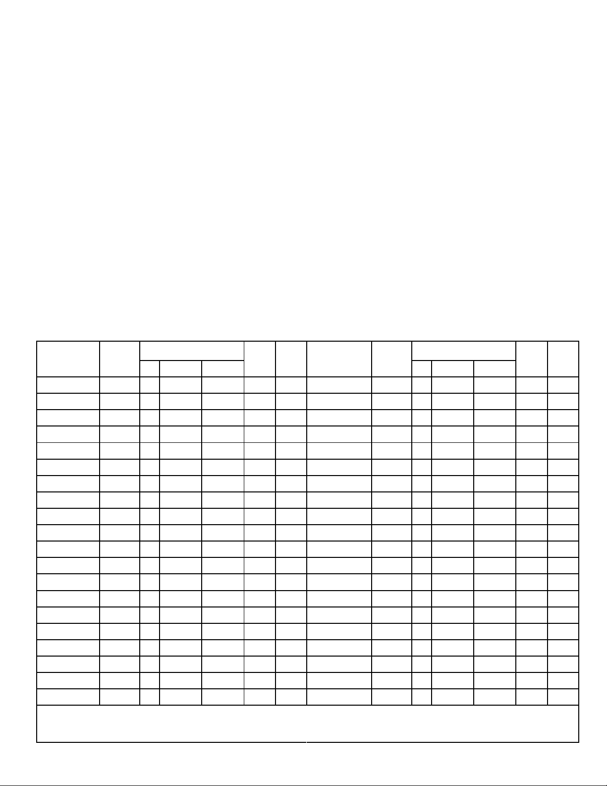
Model Nomina
l
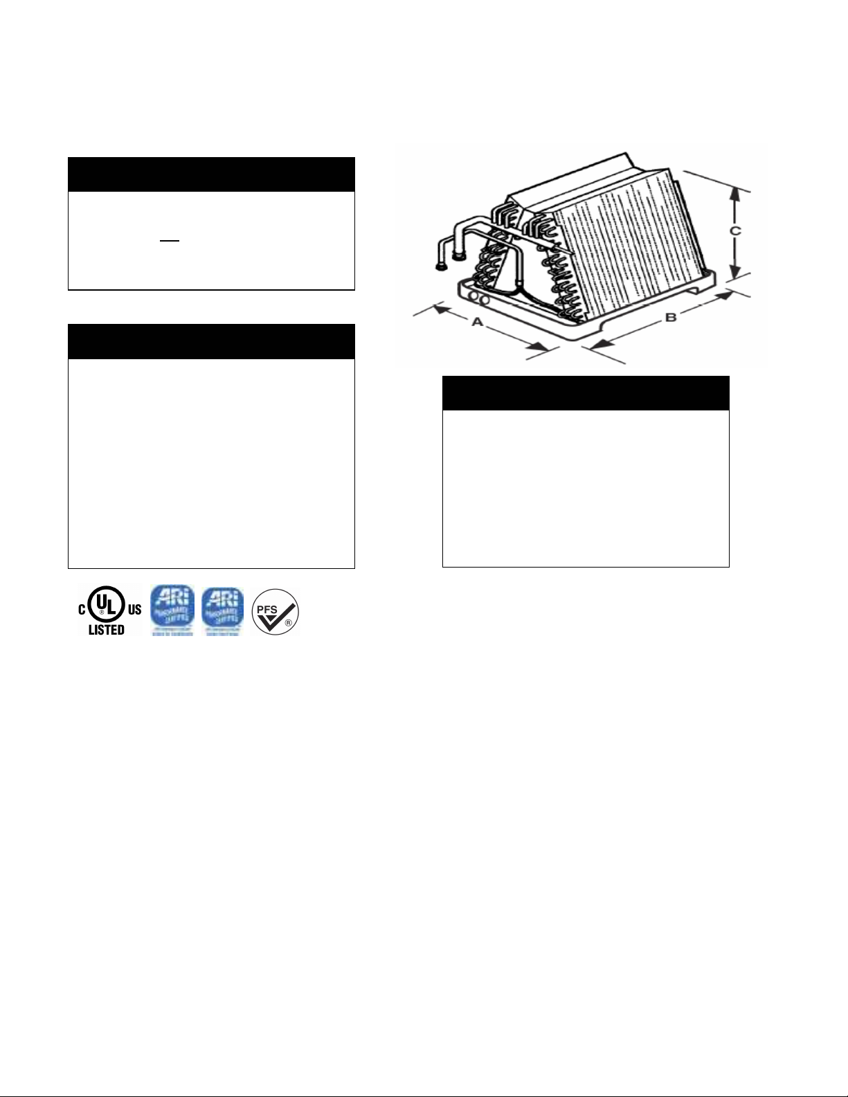
No. Tons A B C Wt. Qty. No. Tons A B C Wt. Qty.
96-8Z3(*)-0P 1.5-2.0 18 19 5/8 16 30 20 98-8W7(*)-0P 2.5-5.0 18 19 5/8 24 1/2 48 12
96-8Z4(*)-0P 1.5-2.5 18 19 5/8 18 32 16 98-8W8(*)-0P 2.5-5.0 18 19 5/8 26 1/2 50 8
98-8Z6(*)-0P 1.5-3.5 18 19 5/8 22 34 12 98-8W9(*)-0P 2.5-5.0 18 19 5/8 28 1/2 52 8
98-8Z7(*)-0P 1.5-3.5 18 19 5/8 24 35 12 98-8W11(*)-0P 2.5-5.0 18 19 5/8 32 1/2 56 8
98-8Z9(*)-0P 1.5-3.5 18 19 5/8 28 37 8 98-8W12(*)-0P 2.5-5.0 18 19 5/8 34 1/2 58 8
96-8G2(*)-0P 1.5-3.0 18 19 5/8 14 30 20 97-9E5(*)-0P 2.5-5.0 18 20 1/2 20 1/2 50 16
96-8G3(*)-0P 2.0-3.5 18 19 5/8 16 31 20 98-9E7(*)-0P 2.5-5.0 18 20 1/2 24 1/2 53 12
96-8G4(*)-0P 2.0-3.5 18 19 5/8 18 33 16 98-9E9(*)-0P 2.5-5.0 18 20 1/2 28 1/2 57 8
97-8G5(*)-0P 2.0-4.0 18 19 5/8 20 34 16 96-R33(*)-0P 1.5-2.0 18 19 5/8 13 29 20
98-8G6(*)-0P 2.0-4.0 18 19 5/8 22 35 12 96-R34(*)-0P 1.5-2.0 18 19 5/8 14 30 20
98-8G7(*)-0P 2.0-4.0 18 19 5/8 24 36 12 96-R36(*)-0P 2.5-3.0 18 19 5/8 18 33 16
98-8G8(*)-0P 2.0-4.0 18 19 5/8 26 43 8 96-R46(*)-0P 3.5-4.0 18 19 5/8 18 38 16
98-8G9(*)-0P 2.0-4.0 18 19 5/8 28 46 8 97-L46(*)-0P 3.5-4.0 18 20 1/2 18 40 16
98-8G11(*)-0P 2.0-4.0 18 19 5/8 32 52 8 98-R49(*)-0P 3.5-4.0 18 19 5/8 28 52 8
98-8G12(*)-0P 2.0-4.0 18 19 5/8 34 52 8 98-R28(*)-0P 1.5-2.0 18 19 5/8 21 1/2 36 8
96-893(*)-0P 2.0-4.0 18 19 5/8 16 1/2 36 20 98-R210(*)-0P 1.5-2.0 18 19 5/8 24 3/4 38 8
96-8W4(*)-0P 2.0-5.0 18 19 5/8 18 1/2 38 16 98-R213(*)-0P 2.5-3.0 18 19 5/8 29 3/4 41 8
97-9E4(*)-0P 2.0-5.0 18 20 1/2 18 1/2 38 16 98-R311(*)-0P 3.5-4.0 18 19 5/8 26 1/2 56 8
97-8W5(*)-0P 2.5-5.0 18 19 5/8 20 1/2 45 16 98-R313(*)-0P 3.5-4.0 18 19 5/8 29 3/4 58 8
98-8W6(*)-0P 2.5-5.0 18 19 5/8 22.5 47 12
Dimensions Coil Pallet Model Nomina
l
Dimensions Coil Pallet
(*) Designates Piston Size or TXV Current Production Models
Page 2
CAUTION!
ATTENTION!
NOTE!
All sweat and quick connect coils are
shipping from factory pressure with nitrogen.
They do not
HFC410A. Relieve nitrogen pressure before
opening the refrigerant circuit.
contain any HCFC22 or
Some Mortex coils have a TXV as the metering
device. However, the sensor bulb is not mounted
due to potential heat damage and / or proper bulb
location. Therefore, after the suction and liquid
line have been properly connected to the coil the
bulb can be mounted on the suction. Many times,
due to space limitations in the manufactured
housing applications it will require the sensor
bulb to be mounted vertically. If that is the case
the bulb should be located at least 6” away from
and bend (elbow) and fastened on the tubing side
opposite the plane of the bend. The bulb should
be insulated using the thermal insulation to
protect it from the effects of the surrounding
ambient temperature. (SEE PAGE 7)
GENERAL COIL INSTALLATION NOTES
1.
On a quick connect coil, test for pressure by pushing
against the diaphragm located inside the quick connect
fitting on the suction manifold. If you are not able to
depress the diaphragm, the coil contains a Nitrogen
holding charge.
To test for pressure on a sweat connect coil, remove
the cap or flare nut on the Schrader fitting and depress
the core valve located on the suction manifold.
2. The blower and duct system must be properly
All Mortex coils are shipped pressurized with
Nitrogen. Coils with sweat or quick connect
fittings are shipped with a nitrogen holding
charge.
ALL COILS SHOULD BE CHECKED FOR
PRESSURE BEFORE LEAVING THE
DISTRIBUTOR OR BEFORE INSTALLATION!
IF THERE IS NO PRESSURE PRESENT, THE
COIL MAY HAVE DEVELOPED A LEAK
DURING SHIPMENT AND SHOULD BE
RETURNED TO THE POINT OF PURCHASE
FOR EXCHANGE.
Sized in order to provide adequate cooling and
heating performance. Select the correct motor
speed tap on the furnace blower to give the
Mortex coils and other accessories installed when
air conditioning is added to manufactured
housing furnaces will comply with HUD
regulations requiring third party approvals.
Efficiency and capacity ratings as required by
HUD are listed in the current AHRI directory for
Mortex [see Summit Manufacturing] matched with
the outdoor units. These coil ratings are based on
air quantities consistent with those that are
encountered in typical manufactured housing air
condition and heat pump applications.
required CFM needed for rated cooling capacity
or upgrade the blower assembly to attain the
proper CFM. Return air filters of generous size
must be provided, in order to avoid contaminating
the coil, blower and ductwork, or restricting
necessary airflow. Failure to deliver the proper air
flow across the indoor coil will cause system
and/or component problems, i.e. TXV
performance problems.
3. It is essential that the indoor coil and outdoor
unit be properly matched and charged with
the proper amount of refrigerant. Incorrect
charge levels will result in inefficient operation.
See more details in installation instructions for the
outdoor unit.
4. For optimum performance and efficiency of air
conditioning or heat pump coils, adjust system
charge and/or superheat/subcooling as
recommended by outdoor unit manufacturers.
Procedures will differ between manufacturers.
5. It is recommended that the coil be sprayed with
liquid detergent thoroughly and rinsed thoroughly
before installation to assure proper drainage of
condensate from the coil fins to eliminate water
blowoff and to assure maximum coil
performance. If not sprayed, approximately 50
hours of break in time is required to achieve the
same results.
Page 3
6. Always be sure coil is installed level or sloped
slightly toward primary and secondary (the
higher of the two) drain fittings. If mandated by
code, connect both drain lines to open drain, but
never to a closed sewer. Pitch drain lines away
from drain pan. Always
water before operating. This step is mandatory in
all manufactured housing installations. Reduction
in size of the drain lines is not recommended and
many times not allowed.
7. A WATER TRAP IS RECOMMENDED ON ALL
COIL APPLICATIONS, BUT IS REQUIRED
PULL THROUGH INSTALLATIONS ON
ELECTRIC FURNACES. FAILURE TO
PROVIDE CAN RESULT IN IMPROPER
DRAINAGE OR POTENTIAL SHOCK HAZARD.
It is mandatory to use an emergency auxiliary drain
pan with any coil or air handler installed in an attic or
above a finished ceiling. It must have its own drain
line (a water trap is not necessary) with its output into
an open drain (not a closed sewer). It should allow
easy visual inspection so that if condensate flow is
seen the homeowner knows that the coil drain pan
lines are plugged and need maintenance.
8.
Refrigerant piping is critical on any coil
installation when the outdoor unit is to be located
below the level of the coil. For proper piping
design considerations, refer to the guidelines
furnished by the manufacturer of the outdoor unit.
9. Check all field installed refrigerant connections
with electronic leak detector, halide torch, or soap
bubbles.
10. Refer to installation instructions provided with the
outdoor unit, gas or electric furnace, and line sets
for completion of system installation.
INSTALLATION WITH ELECTRIC FURNACE:
Typical electric furnace installation consists of a
coil without cabinet installed on top of a downflow
furnace or the coil inside a cavity on either a
downflow or upflow furnace.
The following Mortex installation kits are unique to
manufactured housing air conditioning and these kits
are required to complete the installation.
1. Filter-Electrostatic (95-1741-UES) is required
when using Mortex coil models on all electric
furnaces without cavities. [See #3 below}
2. A Coil Support Bracket (99-3420-03) and coil
support with Insulation Kit (99-3420-02) is
required to support coils in Coleman furnaces.
3 Coil & Filter Cabinets (97-BCC-02N) are
recommended and may times required for
Nordyne furnaces as a preferred option.
Installation procedure:
1. Turn off electrical power to the furnace by
turning off breaker in house panel. CAUTION:
Furnace may be connected to more than one
supply circuit. Do not use furnace
disconnect only. Check power at furnace to
insure power is off.
ATTENTION!
, test drain lines with
ON
2. Remove filter at top of furnace cabinet (Nordyne
or Coleman only).
3. Remove refrigerant line knockout at top of
furnace (Mortex & Nordyne only).
4. Install insulation if needed.
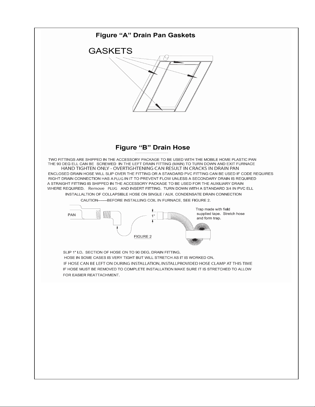
5. Attach drain pan gasket provided with coil to
underside of coil pan and center evaporator coil
on furnace. See figure A on page 5.
6. Attach filters to sides of coil.
7. Route low voltage wiring, refrigerant lines and
drain tubing through floor penetration.
WARNING: If drain hose is below 40 Deg F
during installation warm before expanding
and/or forming.
8. Form 3” deep trap using (field supplied) tape
and (provided) flexible drain hose and connect
to coil pan drain securing with clamp provided.
See figure B on page 5. The most efficient use
of drain material is to form a “P” trap under the
house. All pull through furnaces must have a
condensate trap in the drain line.
9. Connect refrigerant lines per instructions with
line set. Make sure to lubricate quick connect
threads with refrigeration oil for proper mating.
Refer to outdoor unit installation instructions for
additional information on line set hook-ups and
proper torque values.
10. W ith the coil in place seal off any openings at
top or bottom of furnace to prevent air leakage
or air bypass (use silver backed tape provided,
if needed).
11. Turn power on to furnace.
12. Replace front door.
INSTALLATION WITH GAS FURNACE:
Do not install any coil containing refrigerant in a gas
furnace which is to be operated during the heating
season without attaching the refrigerant lines to the
coil. Possible coil damage will result from excessive
pressure build up during heating operation.
Typical downflow gas furnace installation consists
of a coil without cabinet installed in the cavity of a
downflow furnace. Coil with plastic pan is not
suitable for upflow oil furnaces.
Installation procedure:
1. Turn off electrical power to furnace.
2. Remove the lower front panel of the furnace,
and re-route any gas piping in front of coil
compartment as required to install coil.
Contractor must comply with all local, state, and
federal codes and regulations when working with
gas piping. Personal injury or death may result from
3. Remove the coil cover panel(s).
4. Remove knockouts in front left bottom of
furnace for routing of refrigerant lines, low
voltage wiring, and condensate drain.
5. Attach drain pan gasket provided, see figure
“A”, page 5, to underside of coil pan and center
coil in coil cavity.
ATTENTION!
WARNING!
improper installations!
Page 4

6. Connect drain hose to condensate pan fitting,
securing with clamp. See figure “B”, page 5.
7. Remove knockouts from coil cover panel(s), cut
fiberglass insulation covering openings and
reinstall cover.
8. Install silver backed tape provided to cover
openings in interior panel door and over
refrigerant lines to seal around lines
9. Connect refrigerant lines and make sure all
connections are tight and without leaks.
10. Reconnect the gas piping if it was disconnected
and seal off any openings at bottom of furnace.
National, state and local codes must be
followed.
11. Install filter if not located in furnace door.
12. Turn on gas/electrical supply and make final
system check.
13. Replace front door.
SPECIAL CONSIDERATIONS FOR SELECTING
HEAT PUMP COILS
The selection of indoor heat pump coils is much more
critical than selection of indoor coils for air conditioning
units. The differences are as follows:
1. Only indoor coils with expansion/check valve flow
control devices may be used with outdoor heat
pump units. These devices permit reversing
refrigerant flow in the coils when changing from
cooling to heating. All Mortex expansion valves
and pistons have a built-in check making them
heat pump capable when matched with the
proper AHRI rated outdoor unit. CAP TUBE OR
FIXED RESTRICTOR COILS MUST NOT BE
USED WITH HEAT PUMP.
2. Matching of indoor coils for heat pumps
demands that the heat rejection capacity,
internal volume, and equivalent metering
device of the matched coil be at least equal to
that of the smallest internal volume matched
coil recommended by outdoor unit
manufacturer for that outdoor unit.
3. It is important that selection be based on
Mortex recommendation for a specific coil
with a specific metering device to be used
with an outdoor heat pump unit of a specific
make, series, and model number.
4. Failure to conform to proper selection
requirements will affect efficiency, charging, and
reliability and may result in damage to the system
or system components.
5. The matching of specific indoor heat pump coils
with specific outdoor heat pump units as certified
in the heat pump section of the current AHRI
Directory will assure proper and efficient
operation of heat pump systems. See
www.ahri.org.
SPECIAL INSTRUCTIONS FOR CHARGING
HEAT PUMP COILS
Specific detailed instructions for refrigerant charging of
a heat pump system as recommended by the outdoor
unit manufacturer should be followed. These
instructions will differ between manufacturers, but in
general are as follows:
WITH EXPANSION/CHECK VALVE IN INDOOR
COIL, USE LIQUID LINE SUBCOOLING METHOD IN
COOLING MODE. Measure following values from
system: liquid line pressure at gauge and liquid line
temperature. Compare measurements to refrigerant
T&P chart. Allow 20-30 minutes to insure the
system has stabilized before verifying that the
charge is correct. Adjust charge to achieve
outdoor unit manufacturer’s recommended liquid
line subcooling.
IF WITH PISTON METERING DEVICE IN INDOOR
COIL, USE SUCTION LINE SUPER HEAT METHOD
IN COOLING MODE. Measure following values from
system: Suction line pressure at gauge and suction line
temperature. Compare measurements to refrigerant
T&P chart. Adjust charge to achieve outdoor unit
manufacturers recommended Suction line super
heat.
NOTE: Micro-channel condensing unit/heat pump
outdoor unit. The charging should always be
done by superheat, not sub-cooling
.
If the installer encounters a problem using the outdoor
manufacturers suggested charging method technician
should contact the factory for assistance.
NOTE: Good preventive maintenance on heat pumps
is critical to ensure proper airflow across the coils. Low
airflow on indoor coils during winter months causes
high head pressures and premature compressor
damage due to oil breakdown. This problem is normally
the result of a dirty air filter. The installer should instruct
the homeowner of the importance of keeping filters
clean.
CONTACT US FOR HELP OR FOR ANY COMMENTS
ON OUR PRODUCTS.
As we strive to better serve our customers like you, we
are always ready to help you. We also welcome any
comments from our customers concerning quality and
improvements that could be made to our products.
Thank you for the purchase of our product.
Page 5
Page 6
THERMAL EXPANSION VALVE
INSTALLATION INSTRUCTIONS
A. INTRODUCTION
Thermal expansion valve (TXV) can be used on both
heat pump and air conditioning applications. All TV’s
have a built-in check valve making them heat pump
capable. All are externally equalized with nonadjustable superheat and are available with non-bleed
construction. Hard start capability for outdoor units is
required when non-bleed valve is used. The external
equalizer line attached to the TXV has a female flare
nut with built in Schrader valve depressor that
attached to the Schrader valve port provided on most
coils.
B. INSTALLATION NOTES
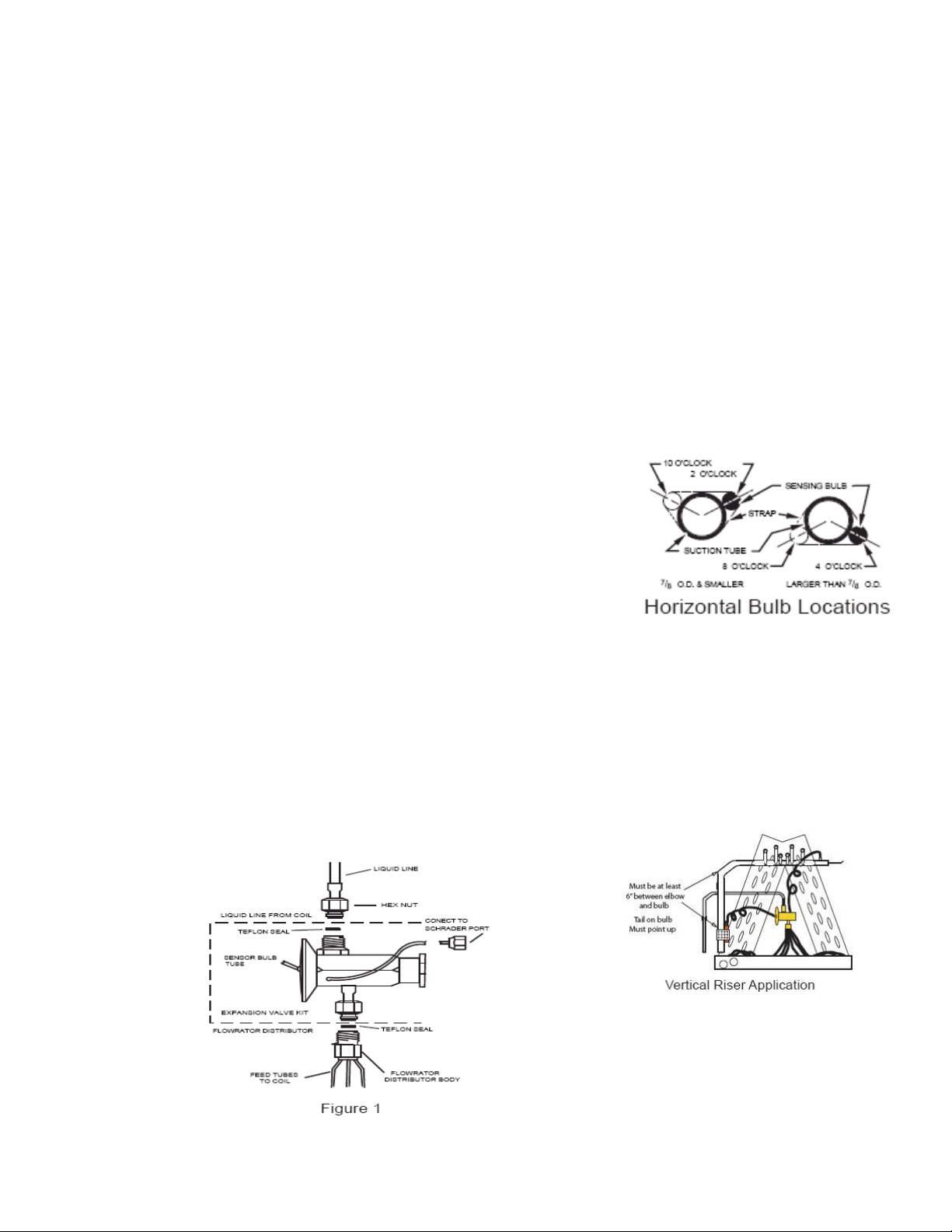
With reference to Figure 1, the TXV assembly is to be
installed between the flowrator distributor and the
existing liquid line attached to the flowrator distributor.
WARNING: COIL IS PRESSURIZED. RELIEVE
PRESSURE BEFORE INSTALLING TXV BY
DEPRESSING SCHRADER VALVE ON COIL
MANIFOLD IF NITROGEN, OR RECLAIM
REFRIGERANT IF COIL HAS HOLDING CHARGE.
C. INSTALLATION STEPS ARE AS FOLLOWS:
1. After coil pressure has been relieved, turn
female swivel nut counter-clockwise to remove.
2. Remove the piston from the flowrator
distributor fitting using a small diameter wire or
paper clip (ALWAYS REMOVE THE PI8STON
FROM THE DISTRIBUTOR BODY WHEN
TXV IS INSTALLED).
3. Attach the TXV by connecting the female
swivel nut on TXV outlet to the flowrator
distributor (aligning Teflon seal first) and torque
swivel nut to 10 – 30 in. lb.
4. Attach liquid line with female swivel nut to
male rotalock fitting on TXV inlet (aligning
Teflon seal first) and torque swivel nut to 10 – 30
in. lb.
5. Remove the cap on Schrader valve port on
coil manifold. Attach equalizer tubing with ¼”
female flare nut that includes depressor to this
male Schrader port. Torque flare nut to 10 – 30
in. lb. If using a different brand TXV, you
must remove the Schrader valve core prior to
attaching the equalizer tube.
6. Install the TXV bulb to the suction manifold
of coil or the suction line using the two bulb
clamps, or single large clamp, furnished with kit.
a. Bulb should be installed on a horizontal run
of the manifold if possible. On line 7/8” OD
and smaller the bulb should be installed at 2
or 10 o’clock. With line larger than 7/8”
OD, the bulb should be installed in a
position of about 4 or 8 o’clock.
b. If bulb installation is made on a vertical run,
the bulb should be located at least 6 inches
from any bend, and on the tubing side
opposite the plane of the bend. On vertical
bulb installations, the bulb should be
positioned with bulb capillary tube at the
top.
c. The bulb should be insulated using thermal
insulation to protect it from the effect of the
surrounding ambient temperature.
7. After completing installation of TXV
(including equalizer tube), it will be necessary to
leak check the coil and evacuate the coil through
the service access fittings of liquid and suction
line valves. SEE COIL AND UNIT
INSTALLATION INSTRUCTIONS.
 Loading...