

Morsø 7340, 7343, 7348, 7350, 7351 User Manual
...
www.morsoe.com
MORSØ JERNSTØBERI A/S . DK-7900 NYKØBING MORS
E-Mail: stoves@morsoe.com · Website: www.morsoe.com
Morsø 7343
Instructions for installation and use
7300-7400
Designed by Monica Ritterband
Morsø 7340, 7343, 7348, 7350, 7351, 7370, 7390
Morsø 7440, 7443, 7448, 7450, 7470, 7490
EN 13240 · NS 3058-3059
Morsø 7443
2
3
1.0 Installing your Morsø stove 3
1.1 Unpacking the stove 3
1.2 Installing the stove 3
1.3 Chimney sweep 3
1.4 Location of the stove/distance requirements 3
1.5 The chimney 4
1.6 Pipe connections 5
1.7 Connecting to a brick chimney 6
1.8 Connecting to a steel chimney 6
1.9 Draught 8
2.0 Firing/using the stove 9
2.1 Lighting instructions and fuelling intervals 10
3.0 Routine stove maintenance 14
3.1 External maintenance 14
3.2 Internal maintenance 14
3.3 Cleaning the stove 15
Additional accessories
We offer a comprehensive line of chimney, floor plate and accessory products that can facilitate the daily operation and maintenance of your Morsø stove.
Likewise, for this stove we have developed a range of accessories designed by Monica Ritterband.
Cast iron
Cast iron is a live material. There are no two ovens that are identical. This is partly due to the
tolerances of the casting process, partly because the ovens are a work of craftsmanship.
Minor unevennesses may also occur in the cast iron surface.
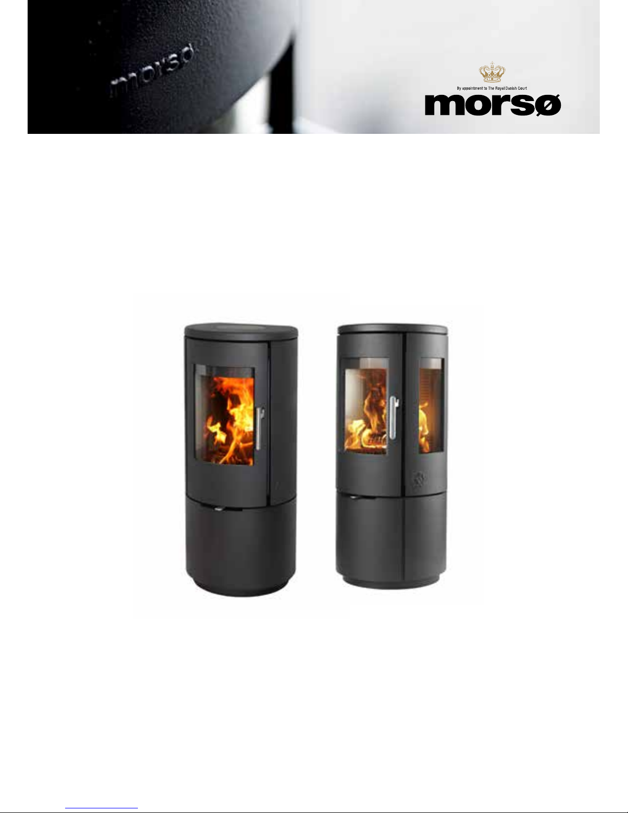
Morsø 7300 og Morsø 7400
Morsø 7400 series has sidewindows. Morsø 7300 series has cast iron side plates.
Enjoy your new Morsø stove!
Morsø, the biggest stove company in the Danish
market, has been making wood-burning stoves of
the highest quality since 1853. Just follow the instructions below, and we are certain that you will be
able to use and enjoy your new stove for many years
to come.
1.1 Unpacking the stove
The cast-iron basic stove is supplied ready for fitting the selected pedestal and upper section.
The Morsø 7300-7400 series weighs between 108 and 122 kg. To avoid damage during unpacking and assembling the stove, we recommend that two people carry out this work.
Remove the cardboard packaging, then lift the cast-iron top plate which is lying loose off the
stove before lifting the stove off the wooden pallet. While fitting the selected pedestal, which
is supplied separately, lie the stove on its back, if possible with the cardboard packaging as a
protective layer. Once assembled, lift the stove up and place it carefully where it is to be permanently located, so that the pipes can be installed. If the stove is to stand on flammable material, place it centrally on a base plate made of steel, glass or other non-flammable material.
Before lighting for the first time, check that all the internal parts have been positioned correctly. The packaging can be disposed of according to the applicable waste disposal regulations.
1.2 Installing the stove
National and local regulations regarding the installation of wood-burning stoves must be observed, as must local regulations regarding chimney connections and chimney installation.
You may want to ask your chimney sweep for advice. However, it is you, your technical adviser
or workman, who is responsible for compliance with the applicable national and local regulations.
1.3 Chimney sweep
As stated, it may be wise to consult your local chimney sweep before installing the stove. In
any event, the chimney sweep must be notified once the wood-burning stove has been installed. The chimney sweep will inspect the installation, and reach an agreement with you
regarding sweeping intervals. If your chimney has not been used for some time, it should be
inspected for cracks, bird nests, etc., before it is used.
1.4 Location of the stove/distance requirements
Distance requirements apply only if the stove is placed near flammable materials. Your new
stove can be positioned as specified on the authorisation sign on the back of the stove if the
walls are made of flammable material.
1.0 Installing your Morsø stove
4
5
We recommend that the stove be installed at least 10 - 15 cm from masonry, in order to allow
heat to circulate and to facilitate the cleaning of the inside and outside of the stove. A layer of
wallpaper on a brick wall is normally viewed as non-flammable material.
The floor
If the stove is installed on a flammable floor, national and local regulations must be observed
with regard to the size of the non-flammable underlying surface that must cover the floor beneath the stove. The underlying surface must naturally be able to bear the weight of the stove
and, if applicable, the steel chimney.
Distance to furniture
The minimum clearance to combustible materials in front of the stove is 850 mm. The minimum distance to combustible materials must be observed; furthermore, it should be considered whether furniture and other items will dry out if placed near the stove.
A wood-burning stove gets hot when it is fired. Caution must therefore be observed, particularly with regard to children touching the stove.
1.5 The chimney
If local regulations permit, the stove may be connected to a chimney already serving another
fireplace (such as an oil-burning stove or another wood-burning stove). Attention should be
paid to any requirements concerning the location of flue pipes if two or more fireplaces are
connected to the same chimney.
The wood-burning stove must never be connected to a chimney to which a gas-burning stove
is already connected.
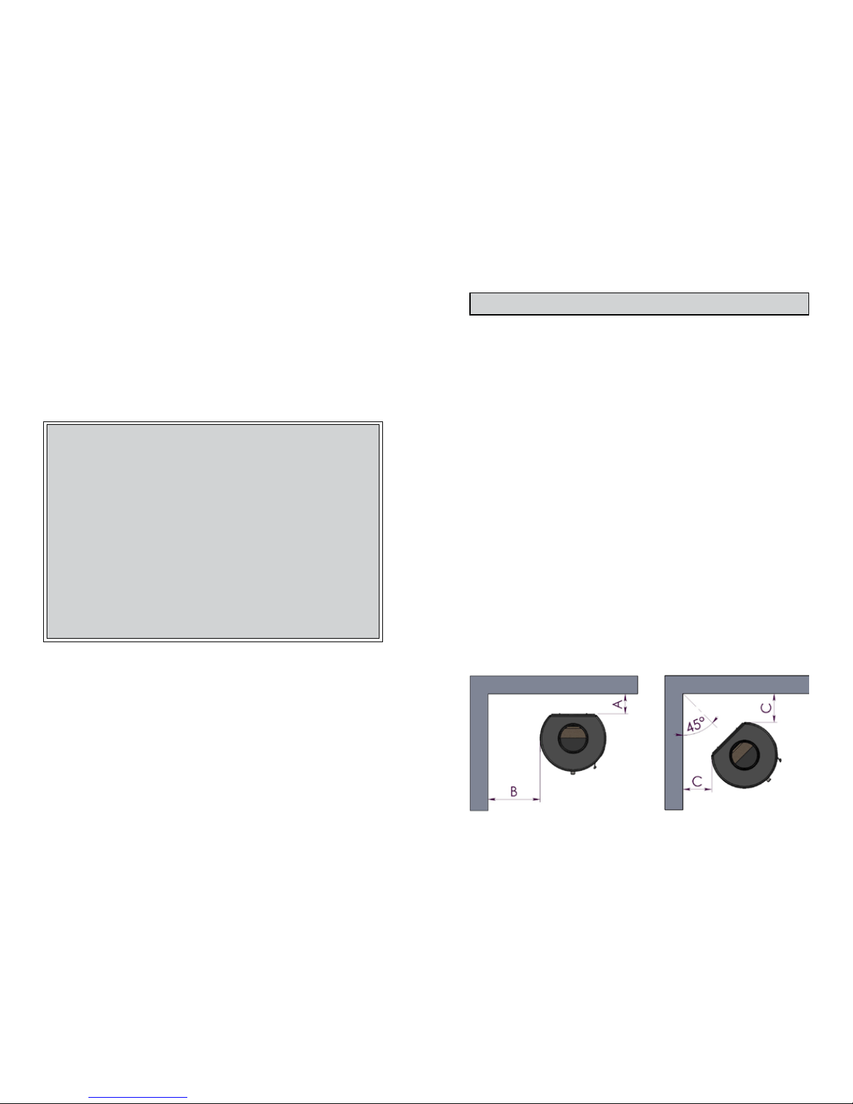
Minimum distance to combustible material:
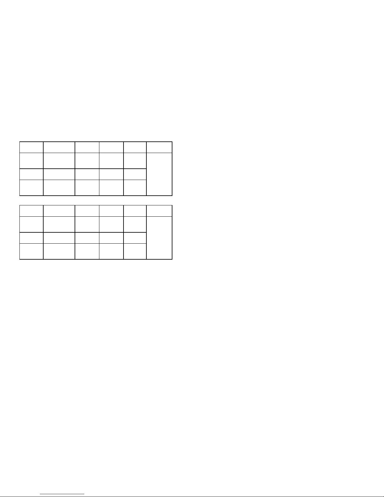
Morsø 7300 series
Installation Stove type Distance A Distance B Distance C Distance
front of stove
Normal
Parallel
Morsø 7300
un-insulated
pipe
200 mm. 400 mm. - 850 mm
Normal
Parallel
Morsø 7300
insulated pipe
100 mm. 400 mm. -
Corner Morsø 7300
un-insulated
pipe
- - 350 mm.
Morsø 7400 series
Installation Stove type Distance A Distance B Distance C Distance
front of stove
Normal
Parallel
Morsø 7400
un-insulated
pipe
200 mm. 450 mm. - 850 mm
Normal
Parallel
Morsø 7400
insulated pipe
100 mm. 450mm. -
Corner Morsø 7400
un-insulated
pipe
- - 350 mm.
An efficient, modern stove places great demands on the chimney, so you should get the chimney sweep to evaluate chimney.
The aperture of the chimney must comply with national and local regulations. In general, the
aperture area should measure at least 175 cm2 (150 mm diameter) for wood-burning stoves.
An overly large chimney aperture will mean that too much energy will be required to heat the
chimney sufficiently to achieve an acceptable draught in the chimney. If you have a brick chimney with a large aperture, we recommend that you install an insulating chimney liner of the
proper diameter. This will increase the draught, and improve the fuel economy.
There are no requirements with respect to specific chimney heights, but a chimney must be
tall enough to provide a good draught, and to ensure that the smoke does not cause any problems. As a general rule, there will be a satisfactory draught if the chimney extends 4 metres
above the stove and at least 80 cm above the spine of the roof.
If the chimney is located along the side of the house, the top of the chimney should never be
lower than the spine of the roof or the highest point on the roof. Please note that there are often national and local regulations concerning the location of chimneys in houses with thatched
roofs. Please see section 1.9 on Draught.
The chimney and the flue pipe must be fitted with cleaning doors, which must be at least the
same size as the chimney’s aperture area.
The chimney must be accessible for external inspection, and it must be possible to access the
cleaning doors and the chimney if it is to be cleaned from the top (e.g. steel chimneys).
1.6 Connecting the flue pipe
Lift the upper cast iron top plate off the stove.
Note: the round cast iron cover plate in the top plate must remain mounted if the stove is
being installed with the flue pipe to the rear, but unscrewed from the upper top plate if the
flue pipe is being installed pointing upwards.
Mounting the flue collar pointing upwards
From the factory, the stove is prepared for installation with the included flue collar pointing
upwards with included screws.
Mounting the flue collar to the rear
With a hammer use light, firm taps to knock out the iron piece on the convection back panel
from the small “bridges” holding the piece in place.
The cover plate for the smoke outlet is unscrewed from the back panel and the fixed onto the
top panel.
Mount the flue collar onto the back panel
Lift the top panel back into place and the round section which is provided can be placed in the
top panel and cover for the blocked off smoke outlet.
The location of the baffle and cast smoke hood
The rear brick and the baffle, which are made from vermiculite, are mounted at the factory.
Make sure that the baffle and rear brick stone are correctly assembled before lighting the stove.
 Loading...