

Morsø 7110, 7140 User Manual
1
MORSØ JERNSTØBERI A/S . DK-7900 NYKØBING MORS
E-Mail: stoves@morsoe.com · Website: www.morsoe.com
MORSØ JERNSTØBERI A/S . DK-7900 NYKØBING MORS
E-Mail: stoves@morsoe.com · Website: www.morsoe.com
Instructions for Installation and Use
7110 & 7140
EN 13240 · (75,5% Efficiency)

2
CONTENTS
1.0 Installing your Morsø stove Page
1.1 Unpacking the stove 3
1.2 Installing the stove 3
1.3 Chimney Sweeping 3
1.4 Stove placement/clearance requirements 3
1.5 The chimney 5
1.6 Pipe connections 5
1.7 Connecting to a masonry chimney 6
1.8 Connecting to a steel chimney 6
1.9 Draft conditions 7
2.0 Firing the stove
2.1 Lighting instructions and fuelling intervals 8
3.0 Routine stove maintenance
3.1 External maintenance 12
3.2 Internal maintenance 12
3.3 Cleaning the stove 13
Enjoy your new Morsø stove!
Morsø, the largest stove manufacturer in Denmark,
has been making cast-iron stoves of the highest quality since 1853. By carefully following the instructions
below, we are certain that you will enjoy many years of
comfortable warmth from your new Morsø stove.
Additional accessories
Morsø also offers a comprehensive line of floor plates and accessory products that can facilitate the safe and efficient operation and maintenance of your Morsø stove.
3
1.1 Unpacking the stove
First remove the outer carton and lay flat next to the stove; this can act as a protective working surface during the assembly procedure.
For shipping purposes, the stove is bolted to the wooded pallet; it should be released from
the pallet by removing the bolts from the underside.
Remove the 2 cast iron baffle plates, leg package and bottom grate from inside the stove and
set aside.
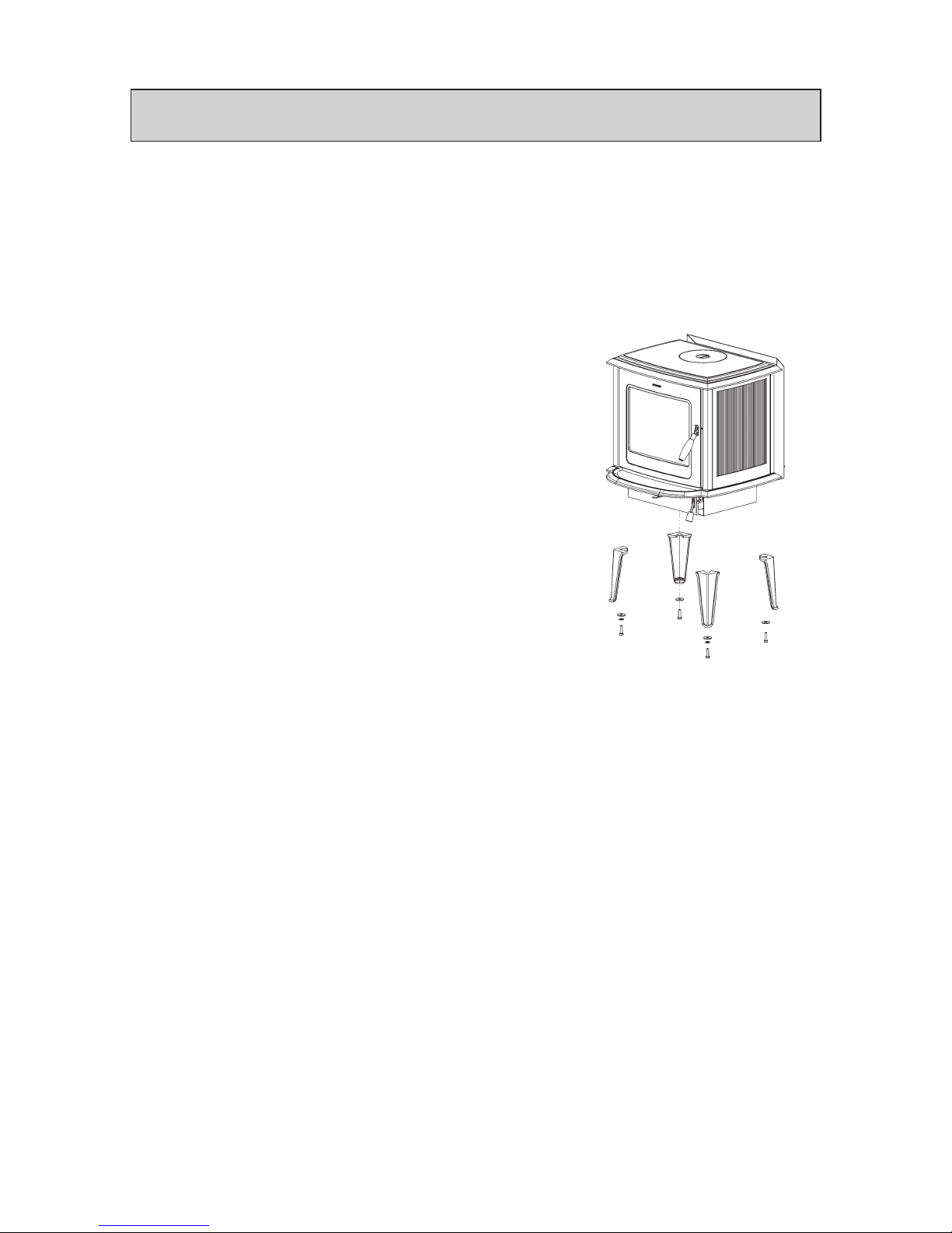
Mounting the legs
Gently lay the stove onto its back; the Morsø
1710 stove weighs 140 kg and Morsø 7140
weighs 150 kg. therefore any lifting or moving of
the stove should be performed by 2 people.
Using the 4 bolts and washers placed inside
the stove, attached the legs to the underside of
the base plate. DO NOT USE THE CARRIAGE
BOLTS AND WASHERS. Also note that you
should use 2 washers for each of the two front
legs.
The stove is intended for intermittent use.
1.2 Installing the stove
The stove and chimney installations MUST comply to all current National and Local Building Regulations; your approved Morsø dealer or your local building control officer can advise
regarding this. Ultimately, it is you and your installer who is responsible that the installation
complies.
1.3 Chimney Sweeping
It may also be wise to consult your local chimney sweep before installing the stove. After your
stove has been installed, it is advisable to have the chimney checked and swept at least once
a year. In any case, if your chimney has not been used for some time, it should be inspected
for cracking, bird nests, etc. before it is put back into use.
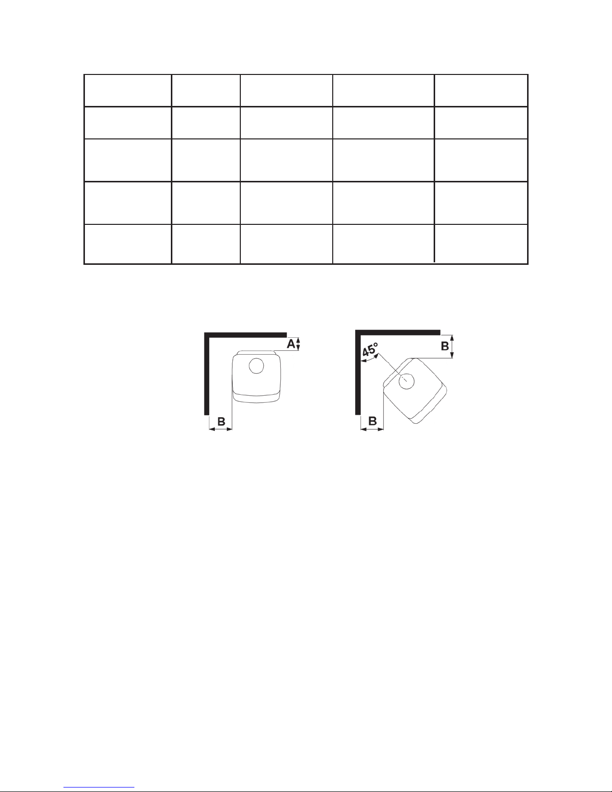
1.4 Stove placement/clearance requirements
Minimum Clearance requirements apply if the stove is placed near to combustible materials.
Permitted clearances to combustible materials are also indicated on the data plate on the rear
of the stove.
In situations where the stove is to be fitted into a brick or non-combustible recess, we recommend that the stove is installed with at least 10 cm clearance to the wall, this will allow heat
to circulate around the stove; also the maintenance of the outside stove is easier. When applied to masonry, a layer of wallpaper is normally classified as a non-combustible surface.
1.0 Installing your Morsø stove
4
Stove type Behind the
stove (A)
To the sides
of the stove (B)
Above the Stove Clearances to
furniture furniture
Morsø 7110
uninsulated flue
300 mm 500 mm 500 mm 1000 mm
Morsø 7110
insulated flue
Morsø 7140
uninsulated flue
150 mm
300 mm
500 mm
500 mm
500 mm 1000 mm
500 mm 1000 mm
Morsø 7140
insulated flue
150 mm 500 mm 500 mm 1000 mm
Minimum clearances to combustible surfaces:
On the floor
National and Local Building Regulations must again be observed when considering the type,
thickness and area of the hearth to be used in the installation. The hearth temperature under
safety test was less than 65°C.
One should of course always make certain that the underlying floor surface can bear the
weight of the stove.
Clearances to Furniture
The clearance requirement from the stove to any furniture should be no less than 1000 mm. It
is always necessary to assess whether or not any furniture or other objects situated close-by
can be affected by heat, i.e. dried out.
The distance to any combustible material in front of the stove is minimum 1000 mm.
The surface of a wood burning stove gets extremely hot when used and therefore special attention to safety is paramount, especially where children or the infirm are present.

5
1.5 The chimney
Only if National or Local Regulations permit are you permitted to connect a stove into a chimney that is shared by another appliance. YOU MUST be aware of any applicable Regulations
in this respect.
The wood-burning stove must never been connected to a chimney to which a gas-burning
stove or appliance is connected.
An efficient modern stove places heavy demands on the chimney, and you should have the
chimney regularly swept and inspected by your approved chimney sweep.
The cross-sectional area of the chimney (at its narrowest point) must comply with National
and Local Building Regulations. Generally, the area needed for a Morsø wood-burning stove
installation should measure at least 175 cm2 (150 mm diameter).
An over-sized chimney is generally hard to keep warm and results in poor draft. In cases
where there is an oversized masonry chimney, it is recommended that the chimney be lined
using an appropriate chimney lining system with the correct internal diameter.
With respect to the chimney termination, all chimneys should terminate in accordance with
National and Local Building Regulations.
Note that National and Local Regulations also apply with regard to the placement of chimneys and flues in connection with thatched roofs. See the section on Draft Conditions, 1.9.
The chimney or flue system must be equipped with access doors for inspection and cleaning.
The size of the cleaning door in the chimney must at least equal to that of the cross-sectional
area of the chimney.
In the event that a chimney fire occurs resulting from faulty operation or prolonged use
of damp wood fuel, close the air vents completely and contact your local fire department immediately.
1.6 Fluepipe connections
The stove is supplied with a factory fitted flue collar (1), this is fitted to the top plate and a
round cast iron blanking plate fitted in the cast iron back panel behind the rear heat shield.
When required, the flue collar can be removed and relocated to the rear flue outlet. To do this,
simply knock out the round panel cut into the rear shield to reveal the cast iron blanking plate
situated behind. Untwist the blanking plate anticlockwise and remove. The flue collar can now
be clamped into position using the fixing lugs attached.
The blanking plate should then be positioned onto the top flue outlet and secured into place
by pressing downwards and twisting clockwise. The blanking plate can also function as an
extra clean-out access whilst performing the annual cleaning service of the stove and chimney.
 Loading...