

Page 1
OWNER GUIDE
This guide is intended to help you care for your gas stove. Please read thoroughly
before using your gas stove and keep for future reference.
Manufactured by Morsø Jernstøberi A/S, Furvej 6, 7900 Nykøbing Mors, Denmark
Distributed by Baxi Fires Division, Wood Lane, Erdington, Birmingham B24 9QP,
England
INSTALLER: Please leave this guide with the
owner
600B474/03
morsø
SQUIRREL
GAS STOVE
MODEL No. 551 – With Open Flue
MODEL No. 552 – With Balanced Flue
We trust that this guide gives sufficient detail to enable your gas stove to be operated
and maintained satisfactorily. However, if further information is required, our
Technical
Helpline will be pleased to help.
In the United Kingdom Telephone 08706 061 065 (National call rates apply in the
United Kingdom). In the Republic of Ireland Telephone 0044 8706 061 065
THESE APPLIANCES ARE FOR USE WITH NATURAL GAS (G20)
OPEN FLUE STOVE MODEL 551 IS FOR USE WITH PROPANE GAS (G31)
WHEN CONVERTED USING KIT NO. 0555111.
BALANCED FLUE STOVE MODEL 552 IS FOR USE WITH PROPANE GAS
(G31) WHEN CONVERTED USING KIT NO. 0555211.
THESE APPLIANCES ARE SUITABLE ONLY FOR INSTALLATION THE
UNITED KINGDOM (GB) AND THE REPUBLIC OF IRELAND (IE).
Page 2

Page 2
LIST OF CONTENTS
Heading Page
SAFETY 3
OPERATING YOUR STOVE 5
The Flame Sensing & Flue Blockage Safety System 5
To Light the Main Burner 6
To Light The Pilot 6
To Turn Off the Main Burner and Pilot 6
To Turn Off the Main Burner Only 6
CLEANING YOUR STOVE 7
Cast Iron Surfaces 7
Opening the Door 7
The Glass Window 7
FITTING THE CERAMIC FUEL EFFECT AND
BURNER COMPARTMENT WALLS 8
MAINTENANCE AND SERVICING 11
Thank you for choosing morsø.
All morsø appliances are designed to meet the most stringent quality, performance and
safety requirements to provide our customers with many years’ trouble-free service.
Your owner guide aims to improve your understanding and appreciation of your gas
fire by providing simple and informative instructions to ensure that you benefit from
the excellent performance and features it has to offer.
OWNER GUIDE
Page 3
SAFETY
Do have the gas stove installed by a competent person. In the United Kingdom,
installation must be in accordance with the latest edition of the Gas Safety (installation
& use) Regulations. In the Republic of Ireland, installation must be in accordance with
all national and local regulations in force.
Do
have the chimney swept prior to installation if it was previously used for solid fuel.
Do
have the gas stove installed in accordance with the installation instructions. On no
account must the fire stand on carpets or other combustible materials. The fire must
stand on a non-combustible hearth surface. The hearth material must be at least 400mm
wide x 420mm deep x 12mm thick.
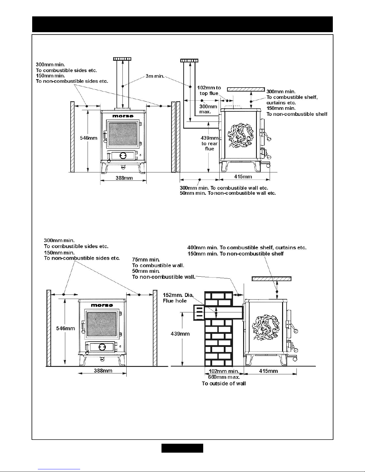
Do provide the minimum clearances shown in figure 1.
Do
ensure that the flue terminal on the outside wall (Balanced flue model 552) is kept
free from all obstructions and blockages.
Do always use a fireguard complying with BS 8423 for the protection of young
children, the elderly or infirm.The cast iron top, front, rear and sides of this stove are
considered to be working surfaces and so will become very hot when in use. Always
take care when using this appliance. Such a guard is also recommended for the
protection of pet animals.
Do
wait three minutes before attempting to relight if the gas stove is switched off or the
flames are extinguished for any reason.(Your gas stove is fitted with a safety device that
will automatically shut off the gas supply to the gas stove, if for any reason , the flame
goes out)
Do
get advice about the suitability of any wall covering near your gas stove. Soft wall
coverings (e.g. embossed vinyl, etc.) which have a raised pattern are easily affected by
heat. They may, therefore, scorch or become discoloured when close to a heating
appliance. Please bear this in mind whenever you are considering redecorating.
Don’t hang clothing, towels or any other fabrics over the gas stove.
Don’t put more loose ceramic coals on the gas stove than the number given in this
guide or use any ceramic coals other than those authorised for this gas stove. Incorrect
combustion could result.
OWNER GUIDE
Page 3
IF YOU SMELL GAS
DON’T SMOKE
EXTINGUISH ALL NAKED FLAMES
DON’T TURN ELECTRICAL SWITCHES ON OR OFF
TURN OFF THE GAS SUPPLY AT THE METER
OPEN DOORS AND WINDOWS TO GET RID OF THE GAS
IMMEDIATELY CALL THE GAS EMERGENCY SERVICE – SEE YOUR LOCAL TELEPHONE
DIRECTORY
Page 4
OWNER GUIDE
Page 4
Model 551
Model 552
Figure 1. Appliance dimensions and clearances
Page 5

Don’t put paper or other materials into your gas stove.
Don’t use the gas stove with damaged base ceramics.
Don’t place any combustible material (rugs, carpet, plastic tiles, etc.) on the hearth
Don’t attempt to clean or service the gas stove until it has been switched off and
allowed to cool completely.
Don’t
use this stove with the door open or with the glass panel damaged or removed.
The door should always be secured with the locking screw (See “Cleaning your stove”).
If the window is damaged or will not close securely the fire must be turned off and not
used until the window is changed or corrected by a competent service engineer.
Don’t leave the stove on if the house is left unoccupied for a long period. We
recommend that the stove is turned fully off.
OPERATING YOUR STOVE
This fire is supplied with ceramic “coals” to simulate a real coal fire. After some use,
the firebox walls and coals may change colour. This is quite normal.
The Flame Sensing & Flue Blockage Safety System.
For your safety, this appliance is fitted with a flue blockage safety device that will shut
down the appliance in the event of abnormal flue conditions. This device is NOT a
substitute for an independently mounted Carbon Monoxide detector.
The device will also automatically shut off the gas supply to the gas stove if the pilot
flame goes out for any reason.
If the device starts to shut off the gas frequently, get
expert advice.
The system incorporates a probe that senses that the heat from the pilot flame is correct.
If this probe is cool, the device will prevent any gas flow unless the control knob is kept
depressed at the PILOT/IGN position.
If, for any reason, the flames go out when the gas stove is hot or if the gas stove is
turned off when hot, always
wait at least three minutes before attempting to relight
.
Always make sure that the door is securely closed before lighting.
OWNER GUIDE
Page 5
PLEASE NOTE
When operating your stove for the first time, some vapours may be given off which may
cause a slight odour and could possibly set off any smoke alarms in the immediate
vicinity. These vapours are quite normal with new appliances. They are totally harmless
and will disappear after approximately twelve hours use.
Page 6
To Light The Pilot
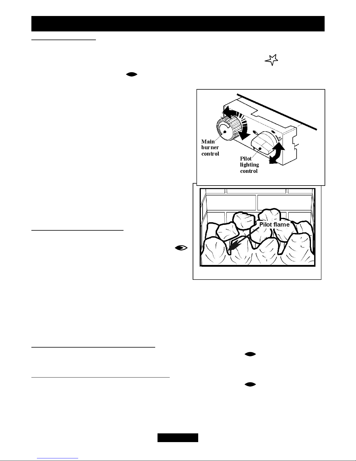
sPush in the right control knob (the pilot lighting knob) and, while keeping it
depressed, turn anticlockwise through the ignition position marked and up to
the pilot position marked
. The spark should light the pilot. The pilot flame can
be seen by looking through the gap between
the coals near the front left corner of the fire
bed (See figure 3).
sWhen the pilot has lit, keep the right hand
control knob depressed for a few seconds to
prevent the flame supervision device from
shutting off the gas supply while its probe
warms up, as explained previously, then
release it.
sIf the pilot does not remain alight turn the
knob back to the off position marked •.Wait
a few seconds and repeat the lighting
sequence.
To Light the Main Burner
sPartially depress the right control knob and
turn to the main burner position marked .
The main burner should now light.
sThe left-hand knob is for burner flame
adjustment. Turning it anticlockwise should
gradually increase the flame height and heat output. Turning clockwise reduces the
flame height and heat output.
s
The burner flame control does not have to be re-set every time the fire is lit. Once set,
it can be left at that position allowing you to use the right hand control only to ignite
the burner at the set flame height.
To Turn Off the Main Burner Only
sTurn the right hand control knob to the pilot position marked .
To Turn Off the Main Burner and Pilot
sTurn the right hand control knob to the pilot position marked
. Push the knob in
at this position and turn to the off position marked
•.
OWNER GUIDE
Page 6
Figure 3.
Figure 2.
Page 7
CLEANING YOUR STOVE
Turn the stove off and allow it to cool completely before attempting any cleaning. Note
that it will retain heat for some time after it has been turned off.
Cast Iron Surfaces
Regular dusting with a dry lint free cloth is all that should normally be necessary. Any
light stains should be removed with a damp lint free cloth. Make sure that the stove
surfaces are completely dry before lighting.
If the paint needs retouching, allow the stove to cool completely. Brush any areas
needing attention with a wire brush (Not enamelled surfaces). Clean off any loose
matter. Touch up with Morsø high temperature stove paint. Apply the paint sparingly.
Two light coats are better than one thick coat.
Opening the Door
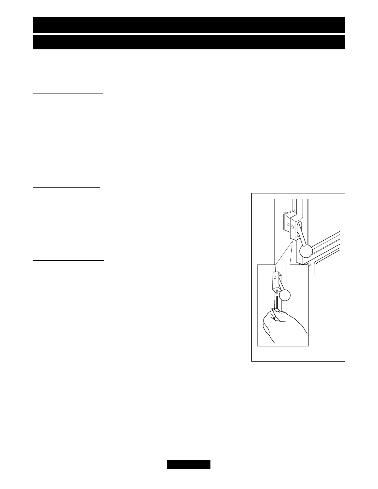
The door is secured with a locking screw. Remove the screw
using the special key supplied with the stove (See figure 4).
Always secure the door with the locking screw to prevent
inadvertent opening and consequent injury or damage
while the stove is in use.
The Glass Window
Any stains on the glass can be removed with a non-abrasive
cleaner such as a ceramic hob cleaner. Never use abrasive
cleaners. Clean the window carefully in accordance with the
instructions supplied with the cleaner.
OWNER GUIDE
Page 7
Figure 4.
Page 8
FITTING THE CERAMIC FUEL EFFECT AND BURNER
COMPARTMENT WALLS
Ceramic fuel effect and Burner compartment
Walls
! This product uses fuel effect pieces and
burner compartment rear wall containing
Refractory Ceramic Fibres (RCF), which are
man-made vitreous silicate fibres. Excessive
exposure to this material may cause irritation
to eyes, skin and respiratory tract.
Consequently, it is important to take care
when handling these articles to ensure that
the release of dust is kept to a minimum.
! Light coatings of soot will usually be burnt
off during the normal operation of the fire.
! Should any soot accumulation become
excessive, the fuel effect pieces and walls should
be removed from the fire for cleaning.
! Cleaning should be carried out in a well
ventilated area or in the open air by gently
brushing with the pieces held away from your face
so that you avoid inhaling the dust.
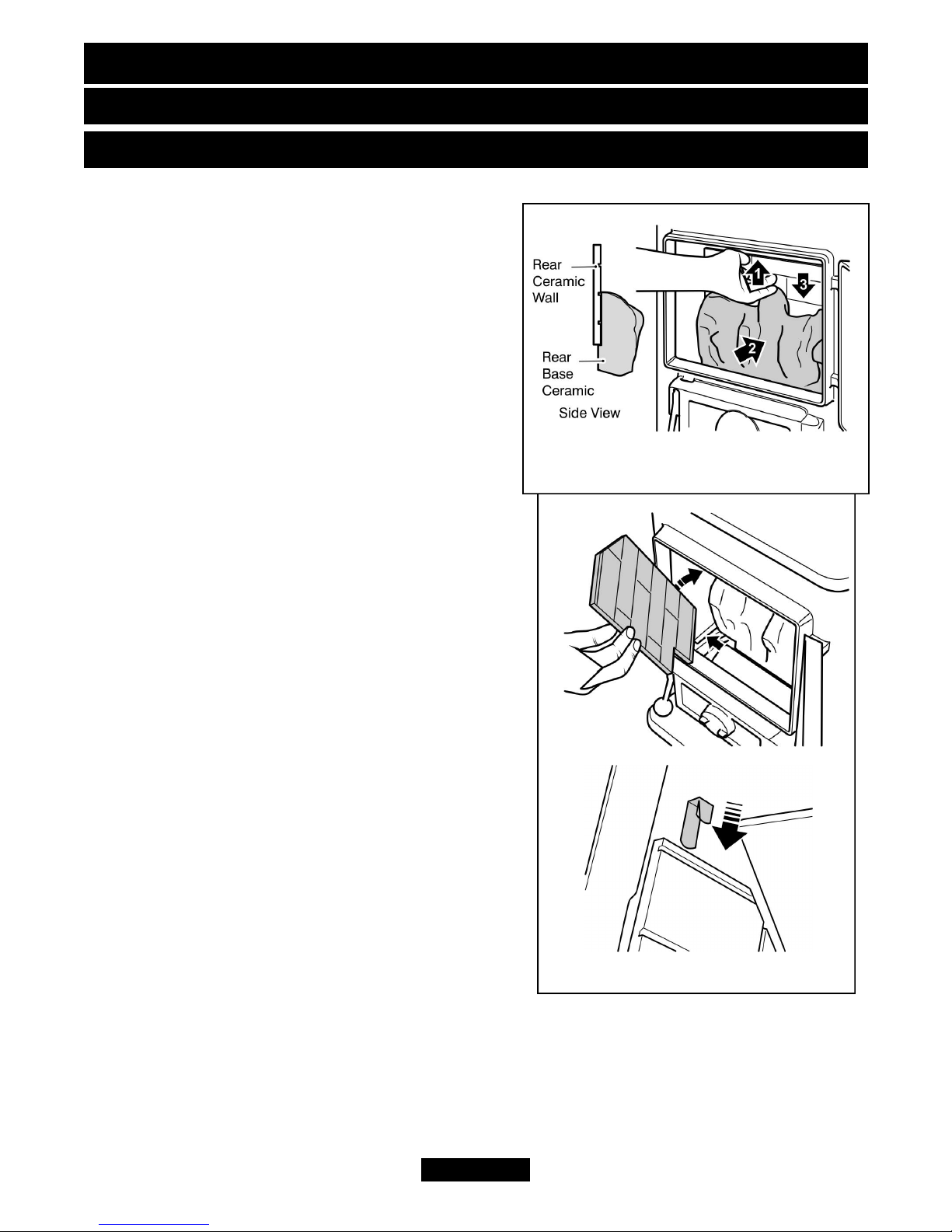
! We suggest that you remove the coals in the
reverse order to that shown in this section of the
guide. When removing the fuel effect and
burner compartment walls it is important that
the front grate is removed before the fuel effect
pieces. To do this hold the front grate firmly
and lift.
1. Place the rear ceramic wall against the back of
the firebox.
2. The rear ceramic wall must be located onto the
ledges at the back of the rear base ceramic (See figure 5). To achieve this, hold the rear
ceramic wall against the rear of the firebox at its uppermost position. Whilst holding the
rear ceramic wall in this position locate the rear ceramic base coal into position (See
figure 5). The rear wall can now be released. Ensure that the rear ceramic wall sits on
the ledge at the back of the rear base coal.
OWNER GUIDE
Page 8
Figure 6.
Figure 5.
Page 9
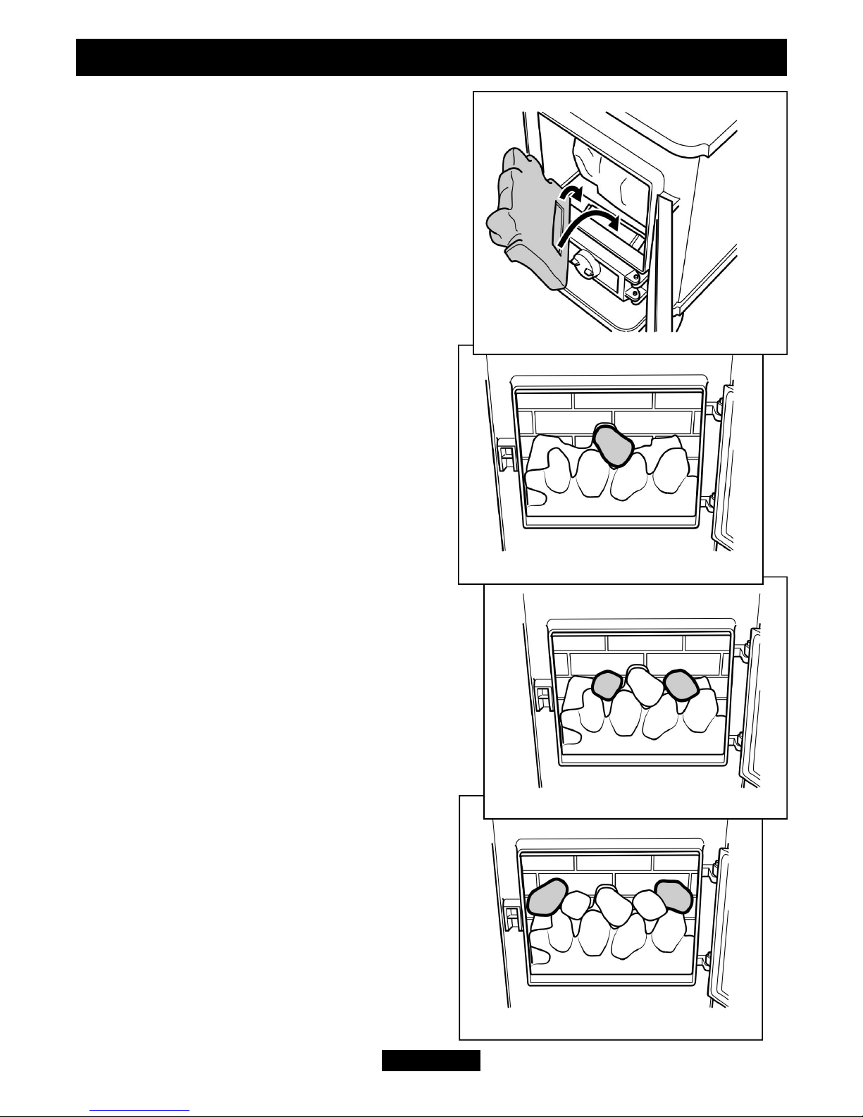
3. Fit the left hand side wall against the left hand
side of the firebox. Locate the bottom of the side
wall into the channel along the bottom of the
firebox (See figure 6). Supplied with the stove
are two ceramic retaining brackets. One for each
side of the firebox. Hold the ceramic side wall
against the steel firebox plate and slide the long
leg of a retaining bracket behind the steel firebox
plate. Push down to hold the ceramic side wall in
place.
4. Fit the right hand side wall against the right
hand side of the firebox. Locate the bottom of
the side wall into the channel along the bottom
of the firebox. Hold the ceramic side wall
against the steel firebox plate and slide the
long leg of a retaining bracket behind the steel
firebox plate. Push down to hold the ceramic
side wall in place.
5. On the front of the burner there is a bracket
for supporting the front ceramic base. At the
rear of the front ceramic base is a recess. Fit
the front ceramic base piece locating the recess
onto the forward projecting part of the burner
bracket (See figure 7).
There are seven overlay coals. There are three
ceramic coals identified with the number’1’. Two
identified with the number ‘2’ and two identified
with the number ‘3’.
6. Locate one of the ceramic coals identified
with a number ‘1’ as in figure 8.
7. Locate the two ceramic coals identified with
a number ‘2’ as in figure 9.
8. Locate the remaining two ceramic coals
identified with a number ‘1’ as in figure 10.
OWNER GUIDE
Page 9
Figure 10.
Figure 9.
Figure 8.
Figure 7.
Page 10
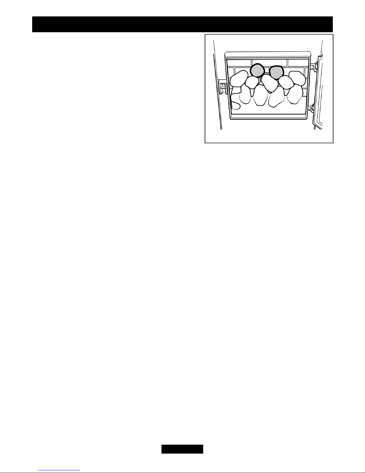
9. Locate the two ceramic coals identified with a
number ‘3’ as in figure 11.
10. Replace the front grate removed previously.
11. Close and secure the door by refitting the
locking screw.
OWNER GUIDE
Page 10
Figure 11.
Page 11

MAINTENANCE AND SERVICING
Regular maintenance
In order to achieve and maintain high levels of personal safety and performance
efficiency, it is essential that the flue is kept clear of any form of obstruction.
In the United Kingdom it is the law that a landlord must have any gas appliance, flue
and pipework which is situated in a tenant’s premises checked for safety at least every
twelve months by a competent person (In the U.K., a CORGI registered installer).
We recommend that all gas appliances and their flues, wherever situated, are checked
annually.
Servicing
!
In the United Kingdom servicing can be carried out either by a Baxi Fires Division
Service engineer or a CORGI registered installer.
! If you require your fire to be serviced by a Baxi Fires Division Service engineer
please contact the Baxi Fires Division service department on 08706 090 081 and
quote the following details;
Model name and number.
Appliance serial no.
In Republic of Ireland call 0044 8706 090 081 for all enquiries.
! If you wish to replace any of the owner replaceable parts listed below,
spare parts
are available nationwide via the ‘interpart stockist network’. For your local
stockist consult Yellow pages under Central Heating.
When ordering please quote the part number shown below.
Description Part No.
Complete set of ceramic coals 5110528
Rear base coal piece 5110532
Front base coal piece 5110531
Bag of 7 top coal pieces 5110533
Complete set of ceramic walls 0572519
Ceramic rear wall only 0572529
Ceramic right side wall 0572539
Ceramic left side wall 0572549
Allen key for door opening 0572559
When fitting replacement parts, follow the instructions contained in this guide.
It is important that only approved parts are used for maximum safety.
OWNER GUIDE
Page 11
 Loading...