

Page 1
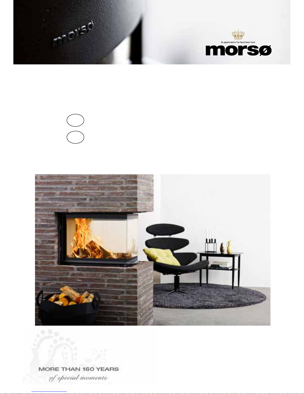
The Morsø S100 Series
UK Instructions for use 1-22
www.morsoe.com
UK Fitting Instructions 23-49
Page 2
Contents
1. Introduction.............................................................................................................. 2
2. Insert types......................................................................................................... 3-12
3. Functional elements........................................................................................... 13
4. Operations handle............................................................................................... 13
5. Fuel............................................................................................................................ 14
6. Special instructions.......................................................................................14-15
7. Air supply..................................................................................................................16
8. Using for the rst time.......................................................................................16
9. Lightning the re..................................................................................................17
10. Stoking......................................................................................................................17
11. Adding wood......................................................................................................... 18
12. Stoking in the transition time........................................................................ 18
13. Stoking with an open door............................................................................. 18
14. Cleaning..............................................................................................................18-19
15. What to do in the event of a chimney re.................................................19
16. Heat-resistant stones.........................................................................................19
17. Sliding door.............................................................................................................20
18. What to do if.......................................................................................................... 20
19. Information for dealers..................................................................................... .21
20. Guarantee.............................................................................................................. .22
1. Introduction
•You have chosen a high-quality Morsø insert - thank you for trusting us. Using
and maintaining your replace correctly (by following these instructions) will ensure your replace functions without problem for a long time to come. Please read
these instructions carefully.
2. Insert types
These instructions describe the function of the replace inserts listed below:
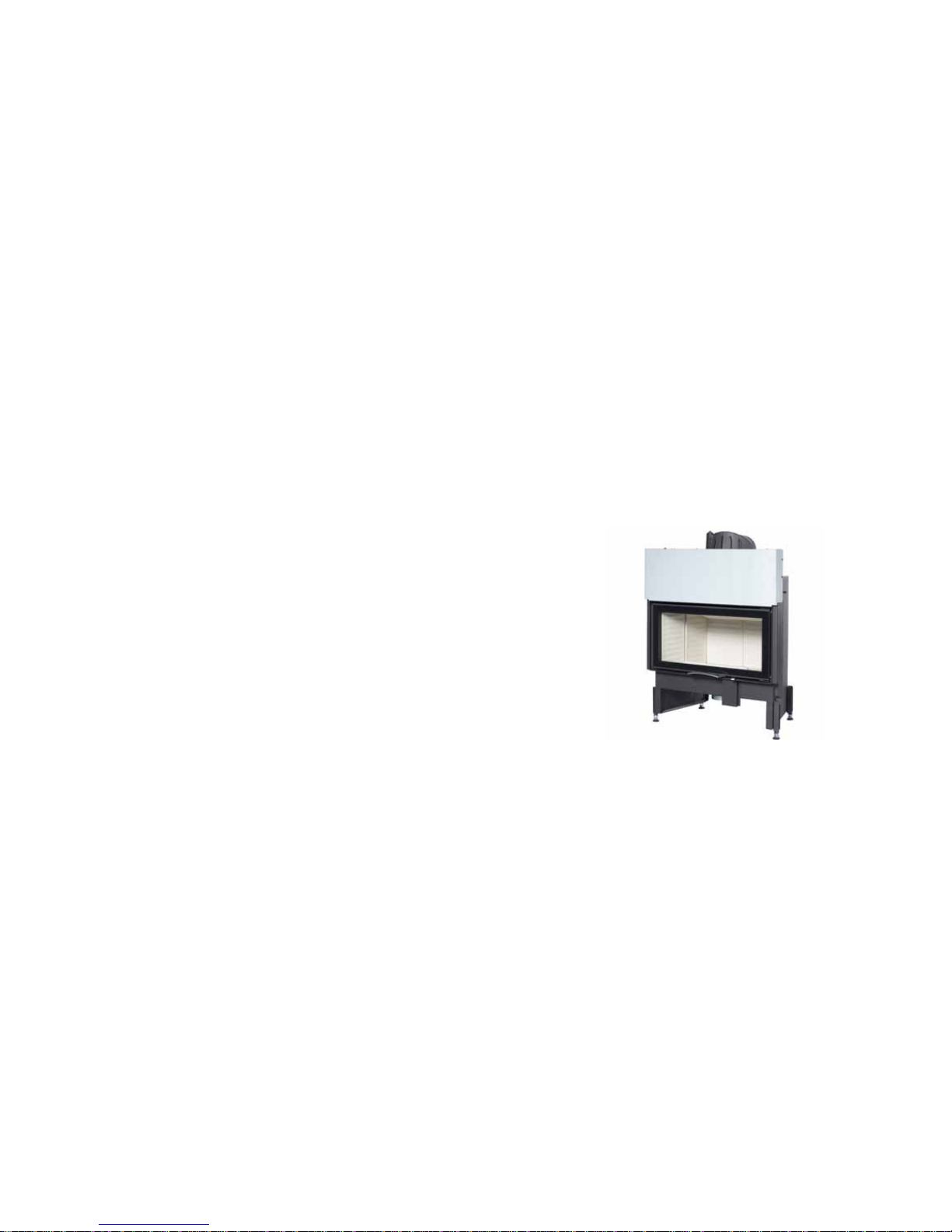
/ONE-SIDED
Morsø S100-12
Width (inbuilt) 1196 mm
Height (inbuilt) 1168-1368 mm
Depth (inbuilt) 573 mm
Weight 267 kg
Output 12 kW
Flue pipe Ø180 mm
Fresh air pipe Ø150 mm
Adapter tting Ø180-Ø150 mm
Optional accessories:
Stainless decorative frame
Heat storage side/back + top
2 3
Page 3
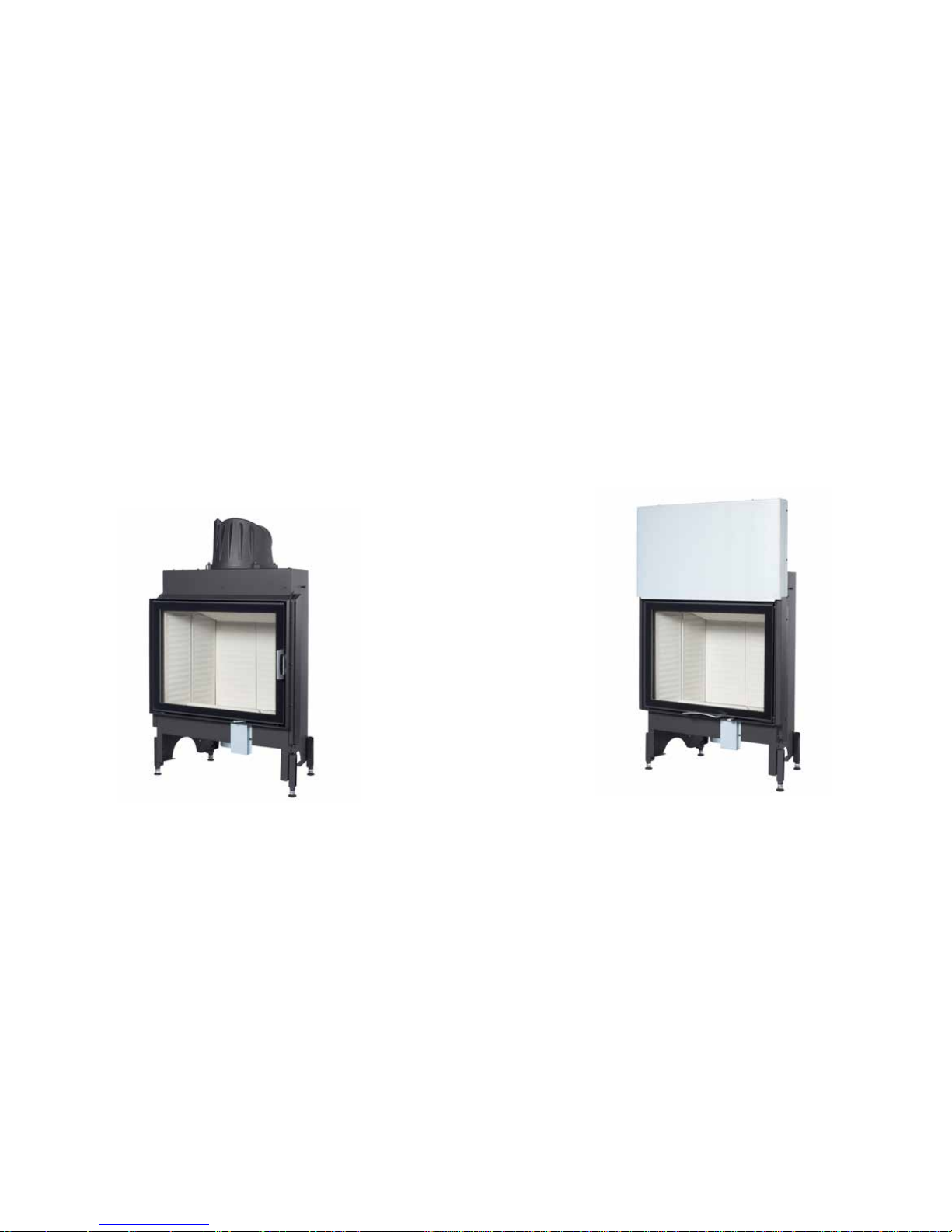
/ONE-SIDED
Morsø S101-11
Width (inbuilt) 795 mm
Height (inbuilt) 1305-1505 mm
Depth (inbuilt) 537 mm
Weight 135 kg
Output 10 kW
Flue pipe Ø180 mm
Fresh air pipe Ø125 mm
Adapter tting Ø180-Ø150 mm
Optional accessories:
Stainless decorative frame
Heat storage side/back + top
Grille + Ash pan
/ONE-SIDED
Morsø S101-12
Width (inbuilt) 805 mm
Height (inbuilt) 1339-1539 mm
Depth (inbuilt) 602 mm
Weight 156 kg
Output 10 kW
Flue pipe Ø180 mm
Fresh air pipe Ø125 mm
Adapter tting Ø180-Ø150 mm
Optional accessories:
Stainless decorative frame
Heat storage side/back + top
Grille + Ash pan
4 5
Page 4
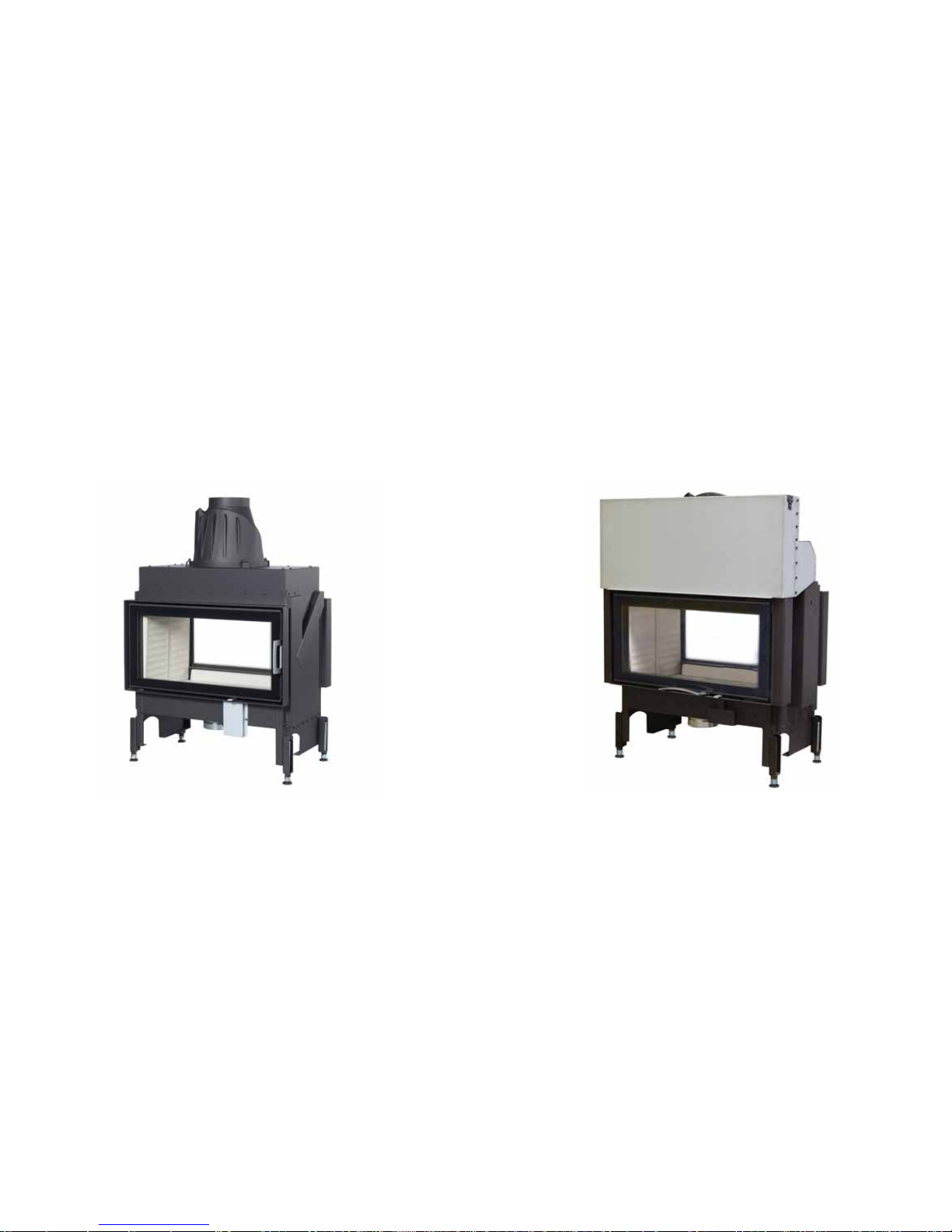
/TWO-SIDED
Morsø S120-21
Width (inbuilt) 773 mm
Height (inbuilt) 1124-1324 mm
Depth (inbuilt) 511 mm
Weight 130 kg
Output 10 kW
Flue pipe Ø180 mm
Fresh air pipe Ø125 mm
Adapter tting Ø180-Ø150 mm
Optional accessories:
Stainless decorative frame
Heat storage top
Grille + Ash pan
/TWO-SIDED
Morsø S120-22
Bredde (indbyg.) 800 mm
Width (inbuilt) 800 mm
Height (inbuilt) 1125-1325 mm
Depth (inbuilt) 537 mm
Weight 129 kg
Output 10 kW
Flue pipe Ø180 mm
Fresh air pipe Ø125 mm
Adapter tting Ø180-Ø150 mm
Optional accessories:
Stainless decorative frame
Heat storage top
Grille + Ash pan
6 7
Page 5
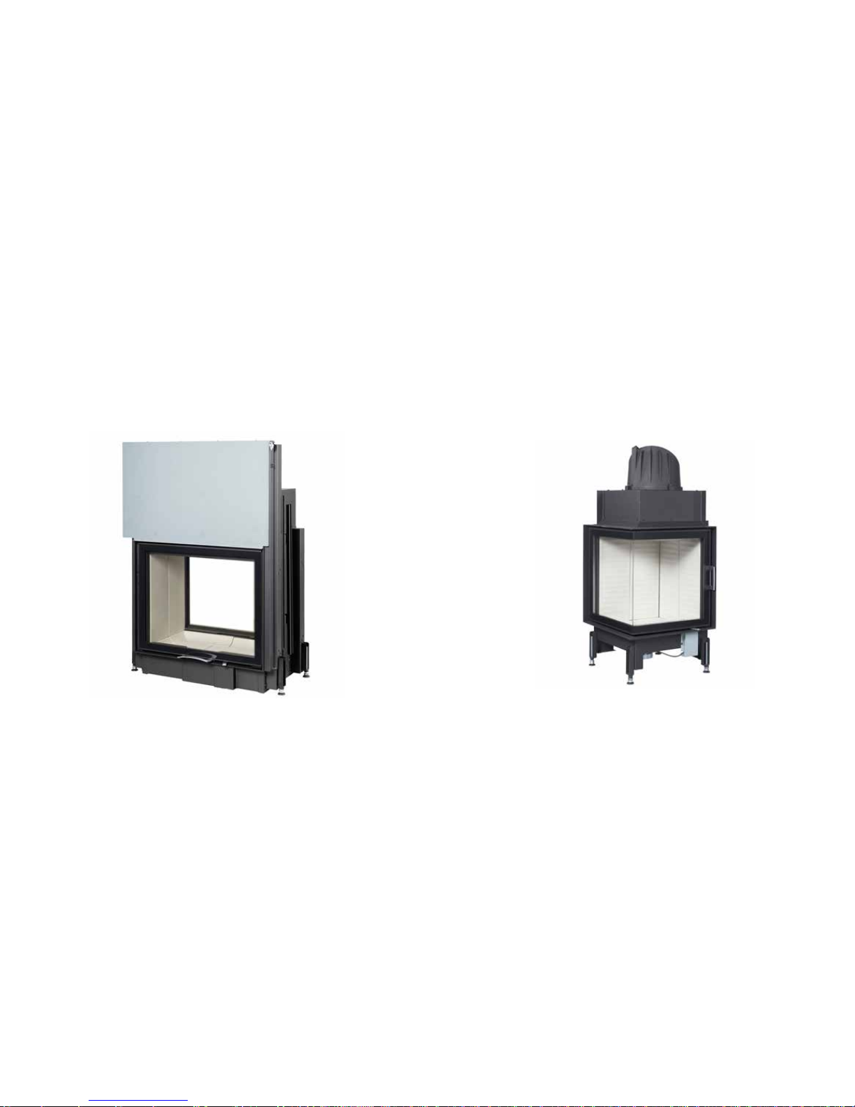
/TWO-SIDED
Morsø S122-22
Width (inbuilt) 963 mm
Height (inbuilt) 1358-1558 mm
Depth (inbuilt) 543 mm
Weight 264 kg
Output 10 kW
Flue pipe Ø180 mm
Fresh air pipe Ø150 mm
Adapter tting Ø180-Ø150 mm
Optional accessories:
Stainless decorative frame
Heat storage top
/CORNER
Morsø S140-41
Width (inbuilt) 613 mm
Height (inbuilt) 1290-1490 mm
Depth (inbuilt) 613 mm
Weight 109 kg
Output 7 kW
Flue pipe Ø180 mm
Fresh air pipe Ø125 mm
Adapter tting Ø180-Ø150 mm
Optional accessories:
Stainless decorative frame
Heat storage sides + top
Grille + Ash pan
8 9
Page 6
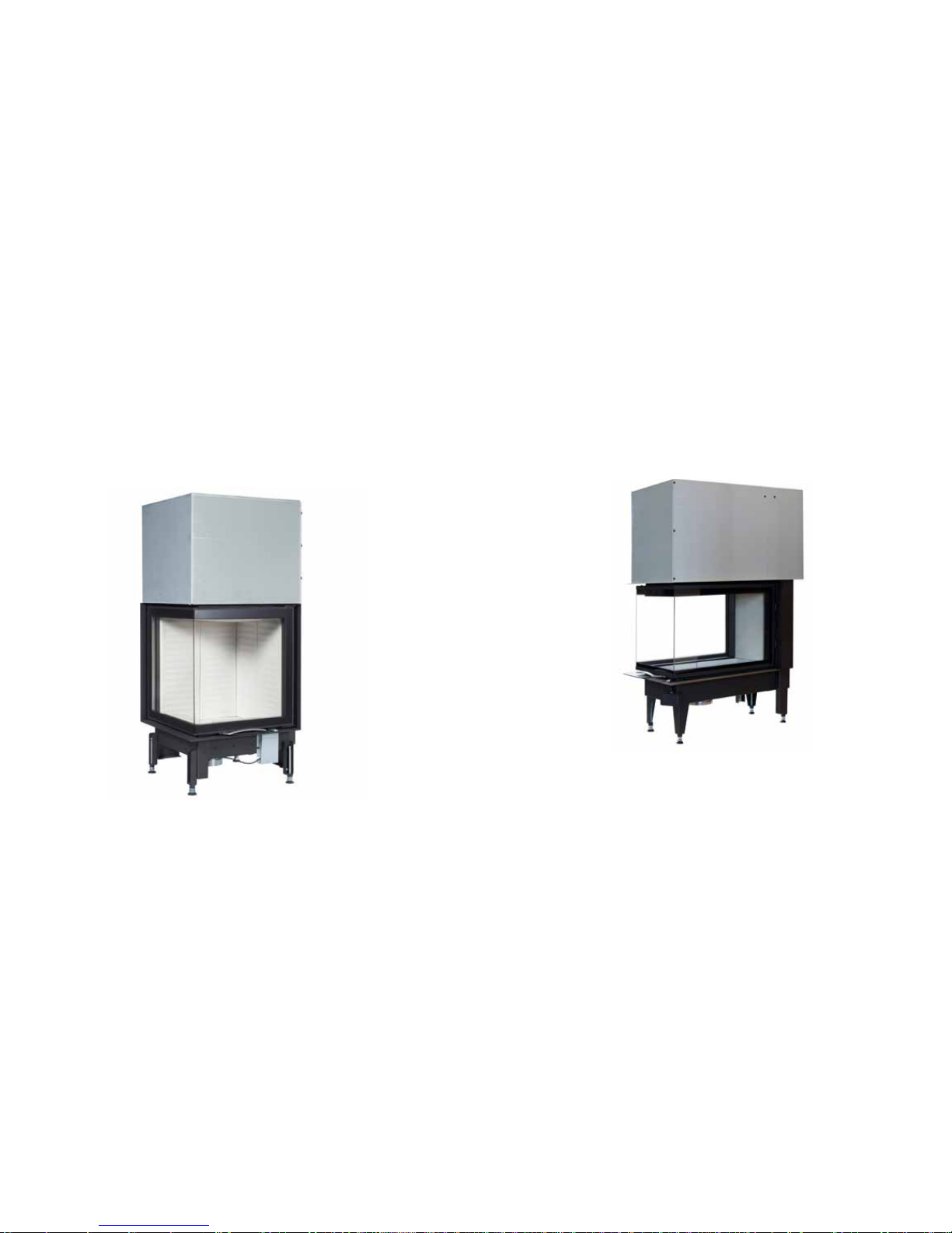
/CORNER
Morsø S140-42
Width (inbuilt) 674 mm
Height (inbuilt) 1290-1490 mm
Depth (inbuilt) 674 mm
Weight 157 kg
Output 7 kW
Flue pipe Ø180 mm
Fresh air pipe Ø125 mm
Adapter tting Ø180-Ø150 mm
Optional accessories:
Stainless decorative frame
Heat storage sides + top
/THREE-SIDED
Morsø S160-32
Width (inbuilt) 550 mm
Height (inbuilt) 1395-1525 mm
Depth (inbuilt) 912 mm
Weight 258 kg
Output 12.6 kW
Flue pipe Ø180 mm
Fresh air pipe Ø150 mm
Adapter tting Ø180-Ø150 mm
Optional accessories:
Support stand
Stainless decorative frame
Heat storage top
Grille + Ash pan
10 11
Page 7
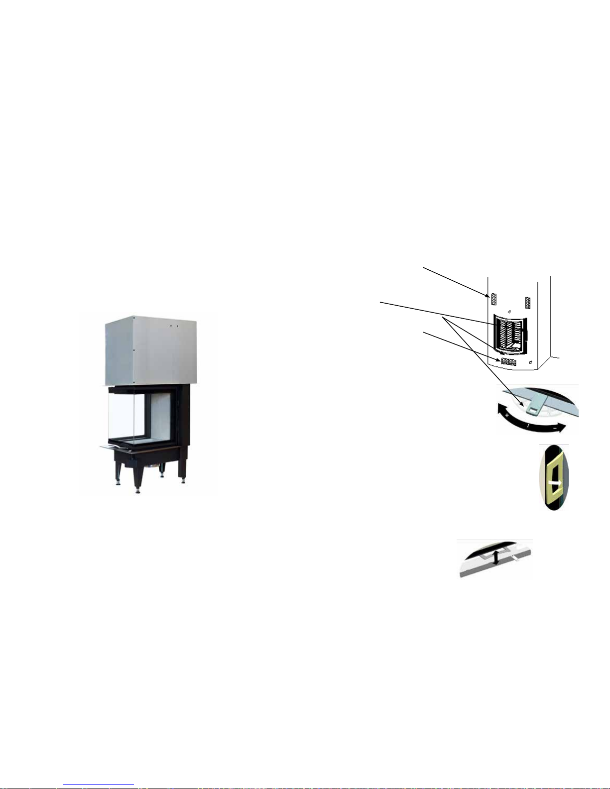
/THREE-SIDED
Morsø S161-32
Width (inbuilt) 550 mm
Height (inbuilt) 1395-1525 mm
Depth (inbuilt) 700 mm
Weight 217 kg
Output 10 kW
Flue pipe Ø180 mm
Fresh air pipe Ø150 mm
Adapter tting Ø180-Ø150 mm
Optional accessories:
Support stand
Stainless decorative frame
Heat storage top
Grille + Ash pan
12 13
3. Functional elements
The S100 series is known for being extremely easy to use.
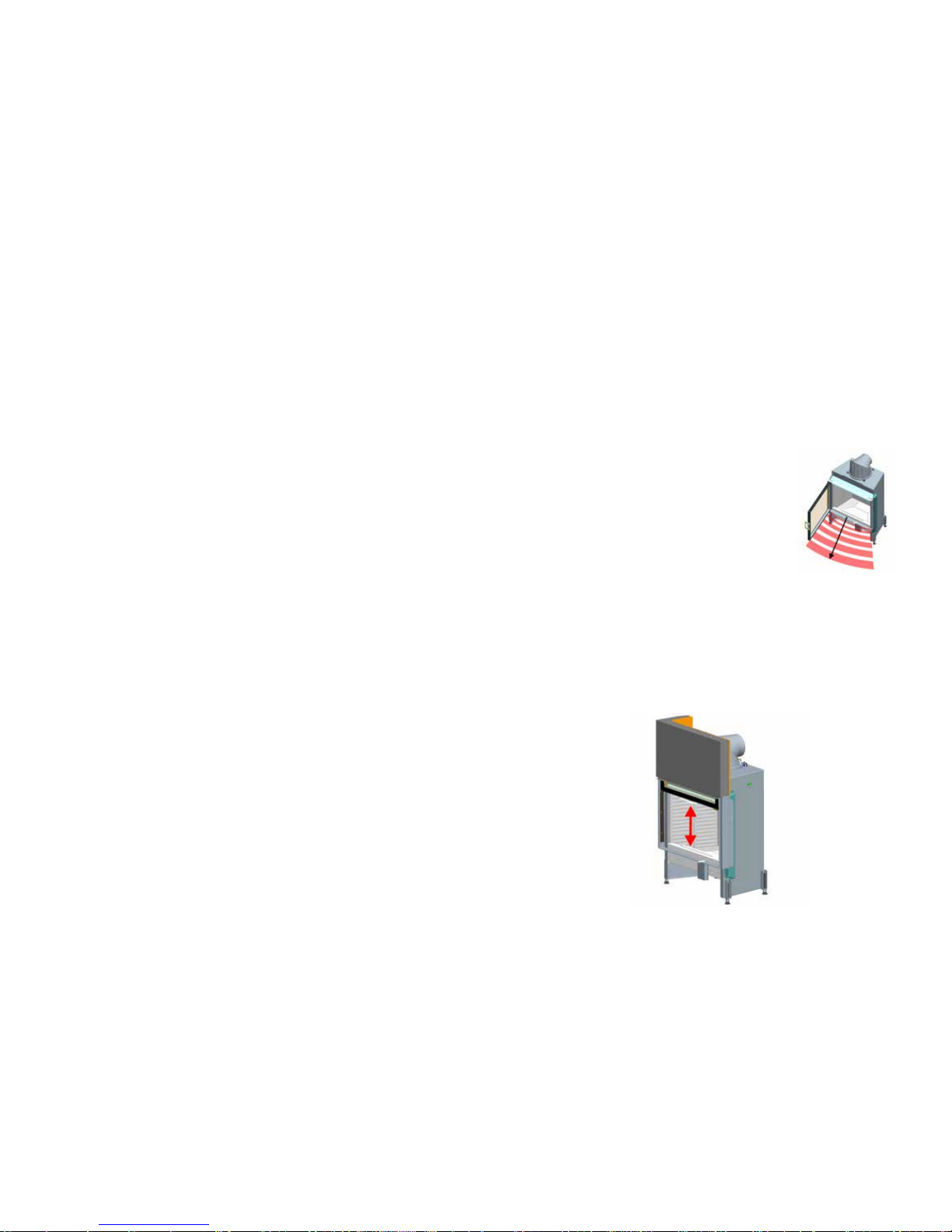
Grill to convection air top
Door handle
Operating handle for combustion air
Grill to convection air base
4.Symbols for operating handle / operating
•Operating handle for combustion air
+ = maximum air supply for rapid stoking
I = medium heat output.
– = low heat output.
•Closing mechanism for folding door
– push the handle outwards:
The door frame is released and the door can be opened.
– ”let go”:
When the door is open, let go the handle/door (at an angle of > 20°) and the door
will close and ”lock” by itself. The replace inset is now ready for use.
• Closing mechanism for sliding door
– Push up = the door opens
– Push down = the door closes
Page 8
5. Fuel - Wood
•Permitted fuel
Dry, well-stored untreated wood (preferably hardwood), wood briquettes.
•Clean combustion
The wood must be dry (relative moisture content < 15%) and untreated. In addition,
the correct amount of wood must be burnt to achieve clean combustion with low emissions.
•Damp wood produces a low heat value and the surfaces inside the replace inset will
quickly become sooted over. A light layer of soot after 2-3 times of use is however normal.
•The guarantee is no longer valid if the incorrect fuel is used!
6. Special instructions
• Please note that the surfaces of the replace inset can become very hot during use.
We recommend wearing protective gloves when operating the replace insert. Please
make children aware of the dangers and keep them away from the replace inset when
in use.
• To stop the replace insert from overheating, do not close the air grates when stoking.
• A maximum amount of wood has been calculated for each replace insert. Larger
amounts than those stated can lead to overheating, which can damage the replace insert!
Maximum amount of wood:
Morsø S100-12 3.4 kg/hour
Morsø S101-11 and S101-12 3.2 kg/hour
Morsø S120-21 and S120-22 3.2 kg/hour
Morsø S121-21 1.7 kg/hour
Morsø S122-22 3.2 kg/hour
Morsø S140-41 and S140-42 1.9 kg/hour
Morsø S160-32 and S161-32 3.4 kg/hour
The second stoking should be done approx. 45 min. after the replace insert is rst lled. Adding additional fuel is therefore often not necessary. However, if you want to stoke the re more, extend the time between lling and reduce the amount of wood (0.5 – 1
kg).
14
• The guarantee is no longer valid if the manufacturer’s specications for determining the
convection air and the chimney’s dimension are not followed or if these are later changed.
80cm
•Inserts with sliding doors are supplied with an extra set of counterweights, the door is selfclosing on delivery, but in all other countries can/must be delivered so the door stays open
when filling.
Note that the door must be kept shut when stoking. (Instructions on how to fit extra weights
can be found in the assembly instructions).
• Only spare parts expressly approved by the manufacturer may be used.
• If necessary, please contact your dealer.
• No structural changes must be made to the inserts!
•No inammable objects must be placed
inside 80 cm of the radiation area of the
replace inset, measured from the edge
of the combustion chamber’s opening
15
Page 9
7. Air supply in the installation room
The insert only functions properly when there is sucient combustion air in the installation room. Please check that there is sucient combustion air before lighting. Set the
handle for the combustion air supply to maximum (+) and leave it in this position throughout the lighting stage. Do not change any equipment on the replace insert that controls or adds combustion air.
8. Using for the rst time
• Remove documents and accessories from the insert.
• Carefully read the instructions for use.
• Allow 4 weeks to pass before using your insert for the rst time to make sure that all
casing and frame elements are completely dry.
• When lighting the re for the rst time, it should be kept at a low level for the rst hour
to allow the cast chamotte stone inside the replace to slowly harden, after which more
wood can be added. Under no circumstances the maximum amount of wood specied
should be exceeded, not even at a later date.
• When the re is lit for the rst few times, there will be a slight smell from the replace
inset, which is completely normal. The smell occurs when the varnish on the insert heats
up and some of the components evaporate. The smell is not toxic but can be a little unpleasant. We therefore recommend that you thoroughly air the room when you light the
re the rst few times.
9. Lighting the re
For correct and safe use of your insert, make sure that the chimney has sucient
draught. This is particularly important to check when using for the rst time (in the stoking period) and in the ”transition time” (e.g. in strong winds, fog etc.).
Hold a lit match in front of the open door. If the ame is not drawn into the chamber’s
opening, a draught in the chimney needs to be made with an intense development of
heat (e.g. with paper or kindling). If this doesn’t work, avoid using the replace insert until
the conditions are right!
• After approx. 5 - 10 minutes (when the wood has caught properly) the handle for the
combustion air supply can be moved to the middle position.
10. Stoking
•When stoking, the handle for the combustion air supply must be no more than 50%
open (i.e. in the middle position), otherwise the added wood will burn too quickly and the
temperature in the replace insert may become too high.
•All air grates should be open.
•After approx. 45 to 60 minutes, add more wood.
16 17
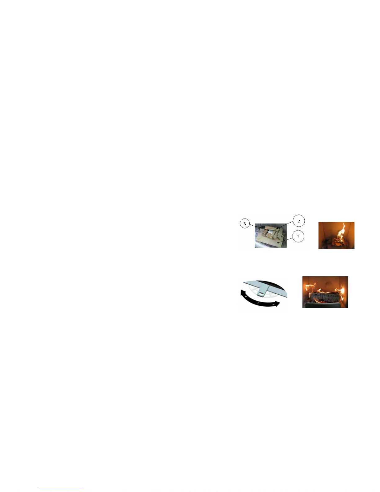
•Push the handle for controlling the combustion air to the left to the ”+” position.
•If an air damper is tted, open it completely.
•Place the larger pieces of wood at the bottom (1), 2-3 pieces (beech, oak, birch) and
then lay the nely split kindling (2) on the top. Place re lighters on the top as it is important that the re starts top-down. It has been shown that particles become smaller when
starting a re this way. (3). Never use petrol, alcohol or suchlike when lighting the re.
Page 10
11. Adding wood
•Open the door slowly to prevent turbulence/underpressure and smoke being drawn
out into the room. The correct time to add new fuel is when the wood in the combustion
chamber has burnt down to embers.
•Add the fuel and close the door.
12. Stoking in the transition time
In the transition time, i.e. in high temperatures outdoors, a sudden rise in the temperature can disrupt the draught in the chimney, such that the smoke is not drawn out optimally. Therefore, stoke the replace insert with a smaller amount of wood and with the
handle for setting the combustion air further over in the (+) position, so that the wood
burns faster (with the development of ames), which will stabilise the draught in the
chimney. In these conditions you may need to remove the ash a little more often.
13. Stoking with an open door (sliding door)
Stoking with an open door is not permitted
Reason: Poorer combustion, development of smoke and re risk!
14. Cleaning
•Remove the ash from the combustion chamber at the right time and at regular intervals and empty the ash box (can be purchased for most models). If you don’t use an ash
box, the middle stone must be taken out and the ash underneath removed regularly
(about every 4 weeks). If this is not done, the pipe for supplying the combustion air may
become covered with ash, reducing the function of the insert.
•The inset must only be cleaned when it is cold.
•The insert and ue pipe (if one if tted) must be cleaned at least once a year or, according to need, to ensure the inset functions properly. Ceramic and or metal chimneys
are cleaned through the cleanout door. All necessary work must be done by a chimney
sweep.
•The chimney must also be cleaned regularly by a local chimney sweep. The chimney
sweep can advise you on the necessary intervals for cleaning and checks.
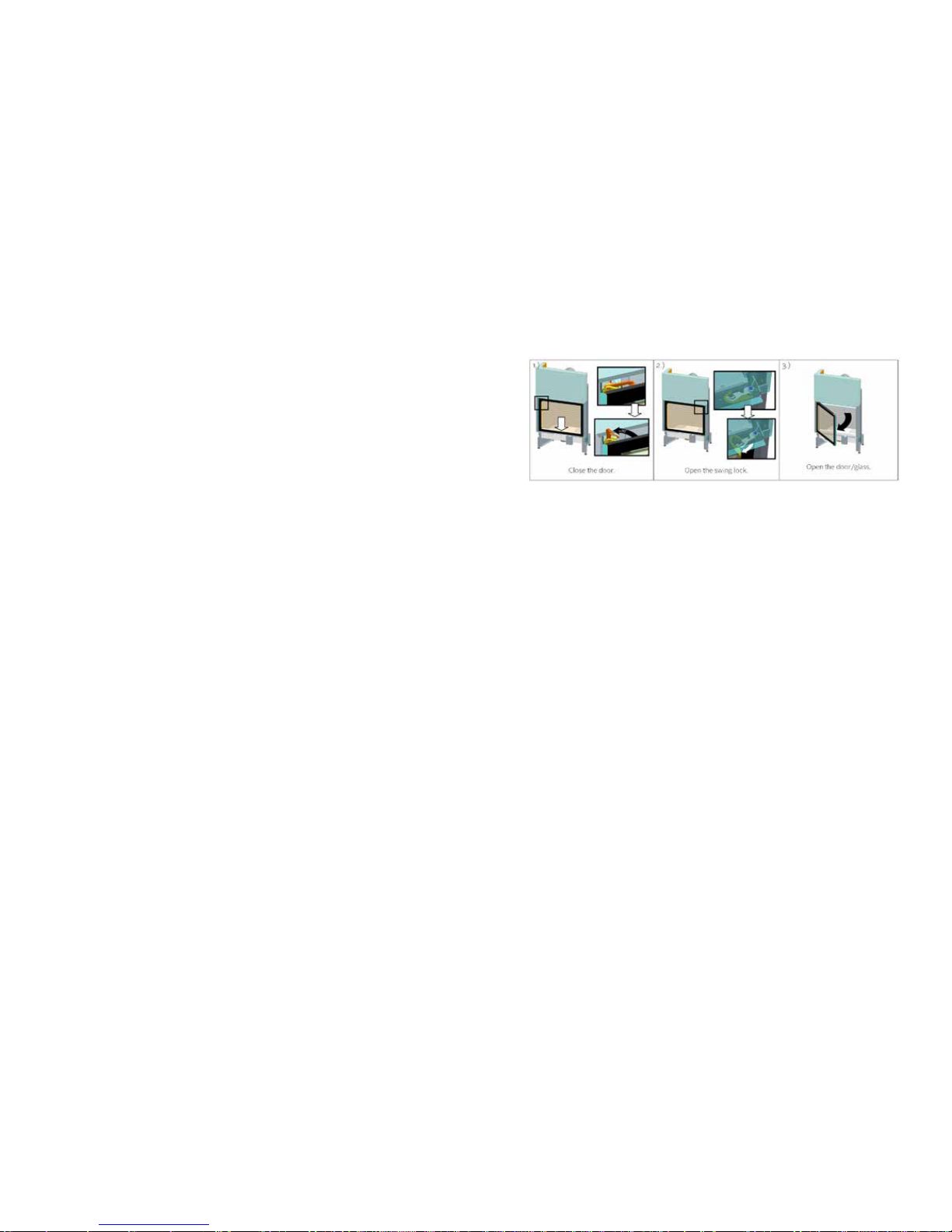
• Cleaning the glass:
• 1.) + 2.) Open the swing locks to the left and right above the door frame. For inserts
with folding doors, push the door handle outwards.
• 3.) The door/glass can be opened.
• Make sure you cover any hearth seat and the oor before cleaning.
• Apply glass cleaner and allow to work for a few minutes.
• Dry the glass with paper/kitchen roll.
• Finally, close the door and the two swing locks.
18 19
15. What to do in the event of a chimney re
A chimney re can break out if the wrong or wet fuel is used due to the deposits in the
chimney.
What to do in the event of a chimney re:
• Call the re service and the local chimney sweep.
• Shut o the combustion air!
• Clear access to cleaning openings (e.g. in the cellar or loft)!
•Remove all inammable materials on or around the chimney. Before using the replace insert again, the chimney sweep must check the chimney for damage.
16. Heat-resistant stones
The heat-resistant stones in the combustion chamber are made from chamotte - a
high-quality material with special combustion properties and an attractive appearance.
During or after stoking, small hairline cracks can appear in the stones, this does not impair the stones’ function. Replacing the stones is not necessary.
Page 11
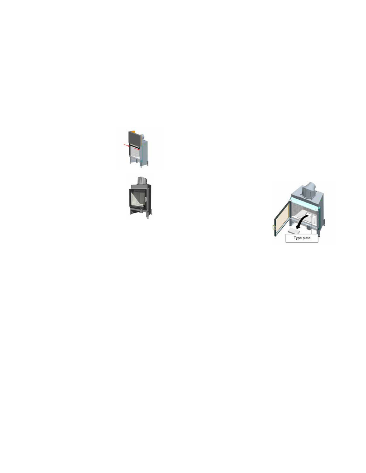
17. Sliding door - ball bearing guide
The ball bearing guide must be lubricated at least once a
year. Push the door up into its topmost position and apply the heat-resistance grease to the rails in a thin layer
(see arrows). ”Fin Grease” can be used and other greases that can withstand the following temperature range:
-30 °C to 220 °C (if necessary ask your dealer).
18. What to do if...?
... the re is barely going or goes out by itself?
• Check that the air damper is open (if one is tted on the chimney).
• Check that the combustion air handle is open (+).
• Is your wood dry enough?
• Check whether the outdoor temperature is too high (>15C°)?
... the room doesn’t get warm enough?
• Check that the convection air grates are open.
• Check whether the draught in the chimney is too strong.
... the re is too strong and combustion uncontrollable?
• Check that the combustion air handle is in the correct position (+ / -).
• Check that the sealing cords on the inside of the door frame/glass are OK and not
damaged.
• Check that the door is closed properly.
• Check whether the draught in the chimney is too strong.
... the glass soots over too quickly?
• A small amount of soot on the glass after stoking for 8-10 hours is normal.
• Have you used dry and clean wood?
• Was the replace insert lit properly before turning down the combustion air?
20 21
19. What information does your installer/dealer need?
• If your replace inset develops a fault, your installer will need the following data:
– Identity number and model name
– Original invoice (date of sale)
• You can nd the type plate under the stone/cast-iron grille/ash box in the combustion
chamber.
Page 12
20. Guarantee
The guarantee is only valid if the assembly and handing over of the unit is undertaken by
a specialist dealer and all applicable building regulations have been complied with. For
your Austroamm replace inset we guarantee perfect function of the body for 6 years,
and 2 years for all other steel and cast-iron parts from the date of rst purchase. Steel
and cast-iron parts that show material or processing faults within the guarantee period
will be replaced with new parts.
Our guarantee does not cover wear parts (e.g. chamotte stones, sealing strips/cord,
base grille/ash grille), surface treatment, varnish and glass. Our guarantee includes costfree delivery of new parts. Labour time and transport time are not covered by the guarantee. Invalid guarantee claims will be returned to sender and charged.
In the event of a guarantee claim, please cut out the form, ll it out and take it to your
Morsø dealer.
Installeret af / Installed by
Kunde / Customer
Til / to
Forhandlerstempel / Dealer’s Stamp
Date of purchase
______________________________
Name of model
_____________________________
Serial no.
______________________________
See manufacturer´s plate
GUARANTEE
Manufacturer:
Morsø Jernstøberi A/S
Furvej 1
DK-7900 Nykøbing Mors
Denmark
The Morsø S100 series
UK Fitting Instructions
22 23
Page 13

Contents
1. General ...........................................................................................................................25
1.1. Rules to be followed ..............................................................................................................25
1.2. Pre-tting checks ..................................................................................................................25
1.3. Sliding door ...............................................................................................................................26
1.4. Setting up the insert ............................................................................................................26
1.5. Positioning the insert ...........................................................................................................26
1.6. Conection to ue ...................................................................................................................27
1.7. Securing during transport ...........................................................................................27-28
1.8. Removing the chamotte securing device ...................................................................28
1.9. Fitting the smoke plates in Morsø inserts ..........................................................29-30
2. Requirements regarding the room, chimney and fresh air connection .....31
2.1. Supplying combustion air from outside/externally.................................................31
2.2. Combustion air pipe ............................................................................................................32
2.3. Support arm for the Morsø S122-22 ............................................................................33
2.4. Chimney requirements.......................................................................................................33
2.5. Connection pieces/Flue ....................................................................................................34
3. Technical data .............................................................................................................34
4. Chimney and replace measurement data .......................................................34
4.1. Minimum diameters ..............................................................................................................35
4.2. Heat insulation .......................................................................................................................36
5. Installation requirements .......................................................................................37
5.1. Installation in front of or to the side of a wall not to be protected ................37
5.2. Installation in front of or to the side of a wall to be protected .......................38
5.3. Convection space ..................................................................................................................38
5.4. Heat insulation on the side and back wall .................................................................39
5.5. Front walling ............................................................................................................................39
5.6. Protecting the oor .............................................................................................................39
5.7. Expansion seams ..................................................................................................................40
5.8. Wall lining ................................................................................................................................ 40
5.9. Decorative beams ................................................................................................................40
5.10. Chimney lining .....................................................................................................................40
5.11. Convection air supply ........................................................................................................ 40
5.12. Ceiling above the replace insert .................................................................................41
5.13. Floor in front of the insert ...............................................................................................41
5.14. Fire safety in the radiation area .....................................................................................41
5.15. Fire safety outside the radiation area .........................................................................41
5.16. Electrical cables ....................................................................................................................41
6. Information on maintenance/repair ...................................................................42
6.1. Folding door insert - Fitting the door ...........................................................................42
6.2. Sliding door insert - Fitting the door .......................................................................... 44
6.3. Converting the radiation frame to right opening of the door...................45-47
6.4. Type plate location ..............................................................................................................47
6.5. Combustion chamber ........................................................................................................ 48
1. General
1.1. Rules to be followed
(Basic requirements)
o Installation standard DIN 18895
o Installation standard DIN 18896
o DIN EN 13384 part 1 and part 2
o DIN 18160-1
o National building regulations
o Regulations for replaces
o Professional rules for the stove and air source heating trade
It is important to choose the right size inset, taking into account the situation regarding
heat requirements, the conditions and needs of the operator, to ensure the good and
economic operation of the inset. Therefore, it can be a good idea to calculate the heat
load (heat requirement).
Please read the tting instructions carefully before you start. All liability and guarantee
claims are invalid in the event of damage caused by not complying with these tting instructions.
Reference is also made to the other instructions in this manual.
Installation of the replace inset and connection to the chimney must be agreed with the
local chimney sweep.
1.2. Pre-tting checks
• Check immediately that none of the delivered items are damaged and that the order is
complete.
• Before tting the equipment, check that all moving parts work. In principle, any faults
should be reported before installation.
• Remember to keep hold of the enclosed user manual and hand it over to the customer
personally, when giving a stoking demonstration for example.
24 25
Page 14
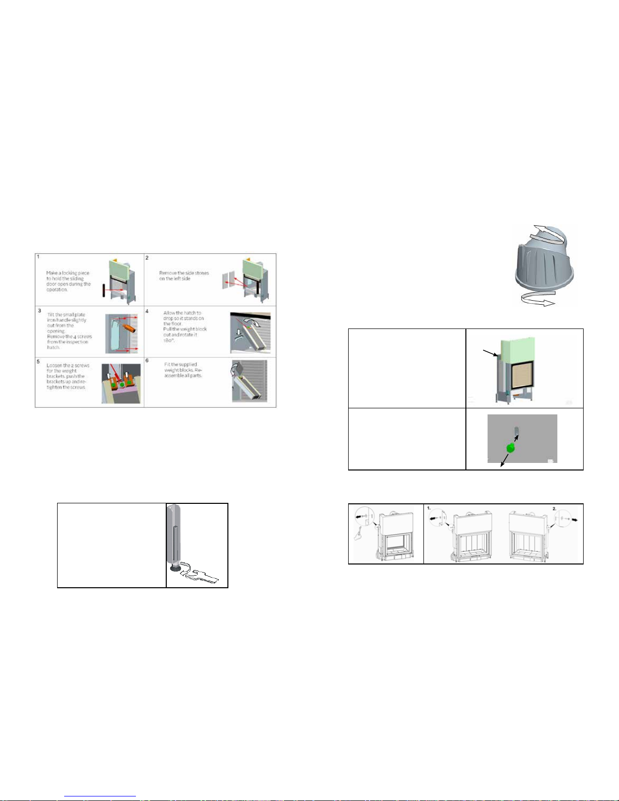
1.3. Sliding door
o Converting from a self-closing sliding door to a non-self-closing.
26 27
1.4. Setting up the insert
Warning!
Please read the re safety guidelines, for example heat insulation and air grate size. If too
much fuel is used in the inset, there is a risk that the chimney will overheat as well as surrounding parts and furniture. This is a re risk!
Place the inset on a prepared,
inflammable and hard-wearing
surface, then set the height of
the four feet using a size 24
open-end spanner.
1.5. Positioning the insert
1.6. Connection to ue
• Preparing the ue pipe:
- You can turn the bottom part of the ue pipe up to 360 °
to lock it in the required position. Then tighten the screws.
- You can turn the top part of the ue pipe up to 360 ° to
lock it in the required angle.
- All the necessary gaskets are already glued in place in the
cast-iron parts.
The door’s counterweight is secured with
a screw on each side of the inset.
Warning: These screws MUST be removed
before the inset is installed!
If the product is to be transported further,
these screws must be re-tted so that the
counterweight is xed securely again.
1.7. Securing during transport
For the S100-12 and S122-22, there is a transport securing screw on both sides. The
procedure is as above.
Page 15
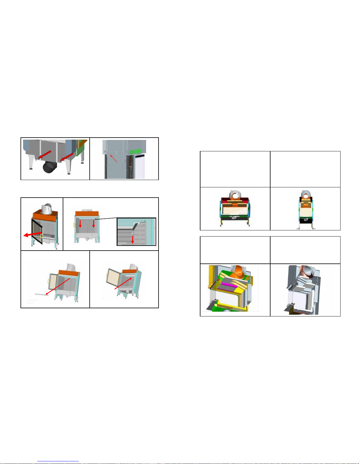
For the S160-32 and S161-32, there are 2 transport securing screws tted towards the
back.
1.8 Removing the chamotte securing device and tting the smoke plate on the S101-11,
S101-12, S140-41 and S140-42
Open the door Release the screws (x2)
Remove the transport bracket Insert the smoke plate
28 29
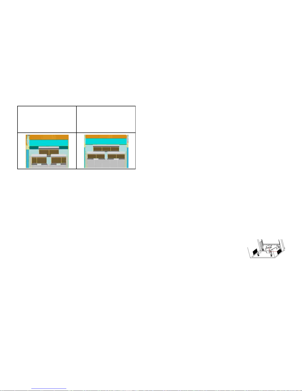
1.9 Fitting the smoke plates in Morsø inserts
All insets are supplied with chamotte smoke plates which are packed separately and
must be tted in the insets. See the tting instructions in the tables below.
Morsø S120-21 and S120-22
Position the top two smoke plates rst,
push the plates together so there is no
gap.
Then position the bottom smoke plates as
shown below.
Morsø S121-21
Position the top three smoke plates rst,
push the plates together so there is no
gap.
Then position the bottom smoke plates as
shown below.
Morsø S160-32
Position the smoke plates as shown in the
illustration below.
Morsø S161-32
Position the smoke plates as shown in the
illustration below.
Page 16
30 31
Morsø S122-22
Position the smoke plates as shown in the
illustration below.
Morsø S100-12
Position the smoke plates as shown in the
illustration below.
2. Requirements regarding the room, chimney and fresh air connection for the insert
The insert must not be placed in
• rooms where the necessary combustion air is insucient/not available,
• publicly accessible areas (such as escape routes),
• rooms that are publicly accessible. Stairs in residential properties, where there are no
more than 2 apartments, are not considered publicly accessible rooms,
• rooms where ammable or explosive materials or compounds are handled, stored or
produced,
• rooms or residences where the air is extracted by means of vents, such as air or hot air
units, ventilation units, tumble driers, unless the function of the insert is ensured.
The following must be ensured if a ventilation unit has been installed
• the systems in question use only circulating air from the room,
• the systems in question have safety devices that automatically and reliably prevent a
vacuum in the unit,
• simultaneous operation of the replace and extraction system is prevented by the safety equipment,
• the ue guide is monitored by special safety devices,
• the ow of combustion air to the inset and the ow rate in the ventilation unit in the
room do not exceed an underpressure if more than 0.04 mbar. This must be maintained
when adjusting or removing easily accessible operating equipment on the ventilation system.
Morsø inserts draw their combustion air solely through an air nozzle located on the underside of the insert. When installing, therefore, a safe and functioning supply of air must
be ensured to the whole of the replace structure. You, therefore, need to observe the
correct dimensions for the pipes/air grates supplying the combustion air. Placing the air
grates in the replace correctly is very important. If this is not done, the replace may not
get sucient air. To ensure an adequate supply of combustion air, we recommend using
a closed air pipe/supply between the air nozzle under the stove from the pipes or grates
that supply the air from the room to the replace.
Important!
The air nozzle for the combustion air must always be connected,
otherwise air cannot be supplied to the combustion chamber
2.1 Supplying combustion air from outside/externally
The combustion air can also be supplied from outside through a pipe led directly in the
replace.
We recommend contacting the chimney sweep to measure the pipework correctly.
Page 17
2.2 Combustion air pipe
The combustion pipe/supply must be made from inammable, rigid material and must
be sealed and available for inspection and cleaning. Condensation can form as a result of
the dew point, which can be treated and prevented with suitable insulation.
In the case of combustion air ducts in buildings comprising more than 2 oors and combustion air pipes that traverse rewalls, the pipes/ducts must be designed so that re or
smoke cannot travel to other oors or areas.
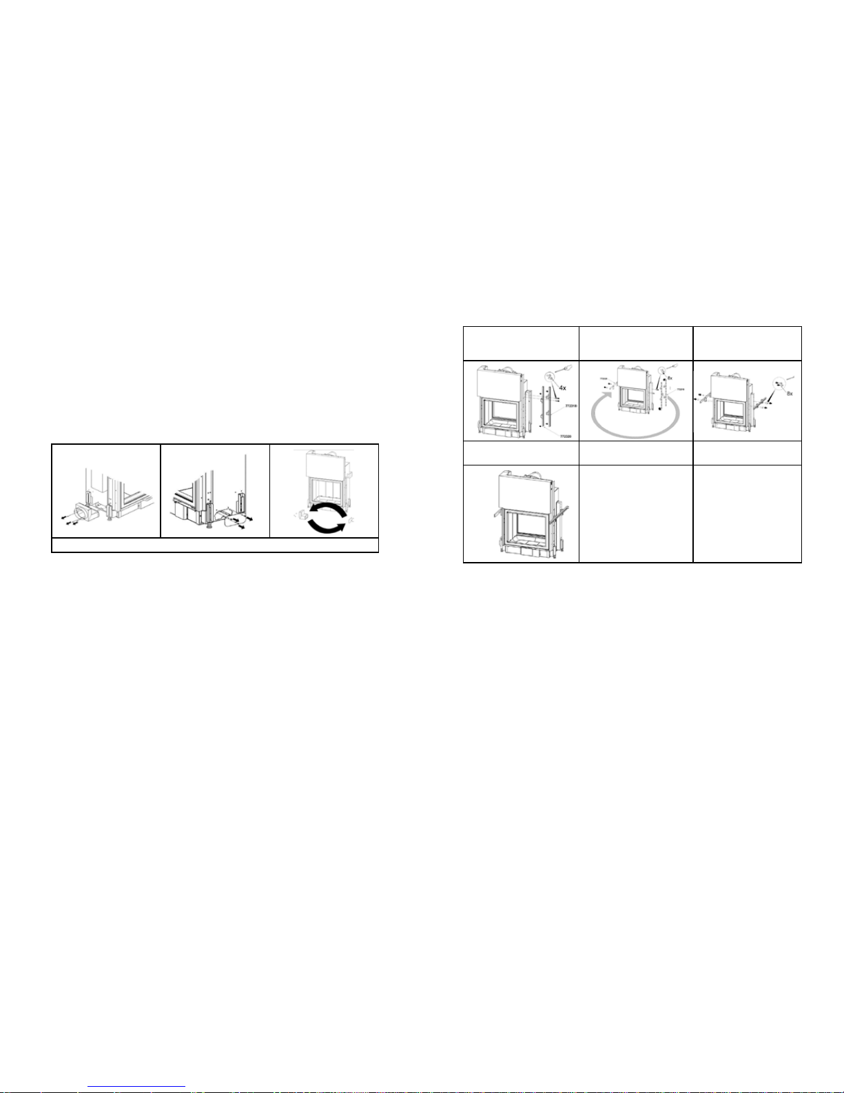
Models S100-12 and S122-22 only
The fresh air pipe can be tted on both the right and left side.
The separate fresh air pipe and blind plate are fastened with 3 screws.
2.3 Support arms for the Morsø S122-22
Remove the screws for the
support arms
Remove the xing screws
and rotate the support arms
so they are horizontal.
Fit the support arms with
the xing screws.
The S122-22 tted with support arms
The insert can now be moved.
Note: When removing the
support arms, the screws
must be re-tted in the insert.
This is to prevent leaks in
the combustion chamber
2.4 Chimney requirements
Before setting up or installing a Morsø inset, the dimensions and quality of the chimney
must be checked against existing local/national regulations. The mathematical proof for
the correct function of the chimney is stated in accordance with DIN EN 13384. The calculation takes into account that even the very large volume of air that will occur with an
open door (when adding rewood) can be removed safely.
The correct function of the inset depends on correct the chimney conditions.
It is important to ensure that all openings that lead to the same chimney, e.g. the cleanout door, are closed.
Several connections to the same chimney:
All Morsø’s insets in these instructions have been tested to DIN EN 13 229 with self-closing door (labelled A1) and approved. These units can be connected to a chimney with
several connections (apart from chimneys with balanced ventilation). The calculation
has been done in accordance with DIN EN 13384 part 2.
32 33
Page 18
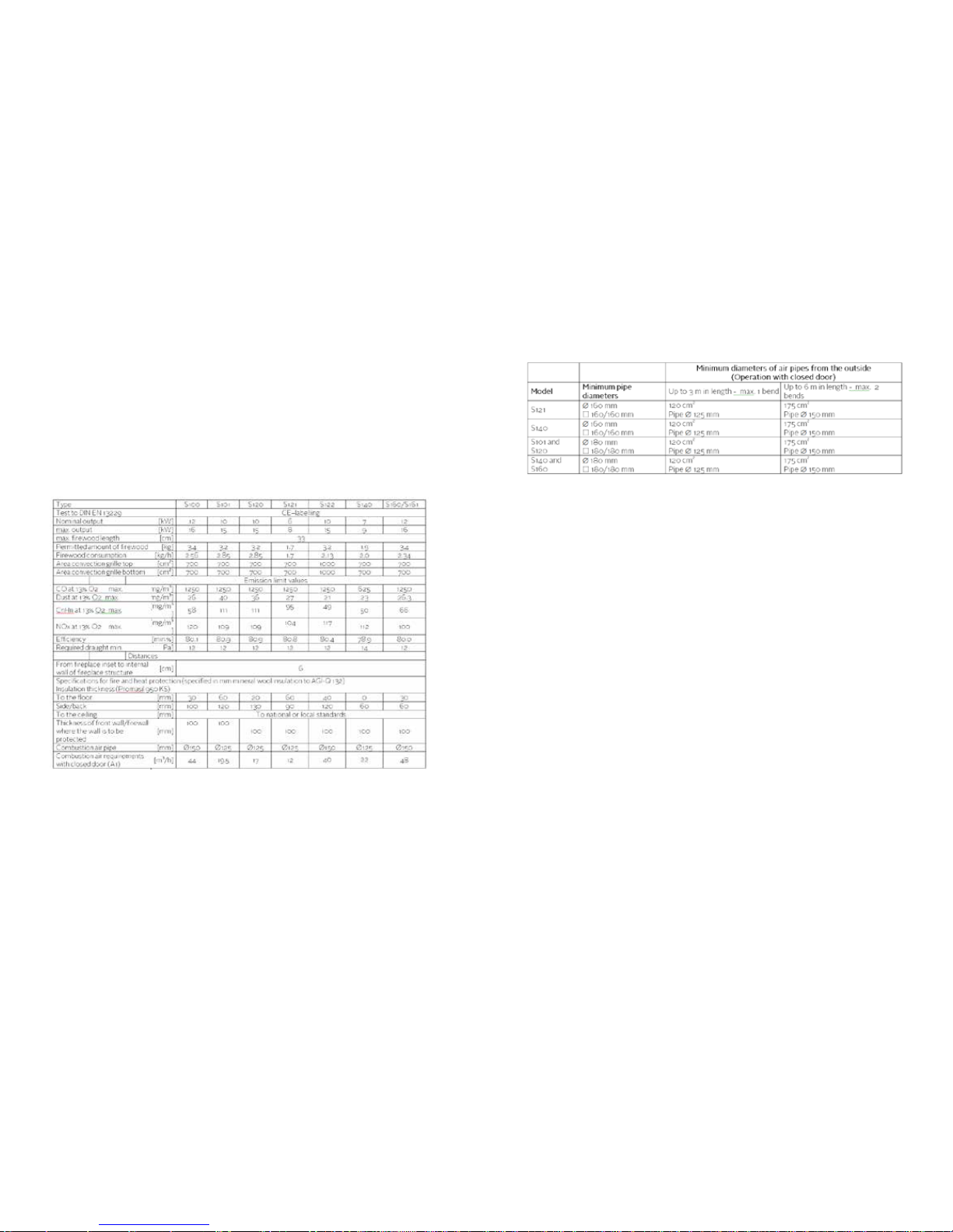
2.5 Connection pieces/Flue
The connection pieces/ue must be dimensioned to DIN EN 13384.
They must be steel pipe with a min. thickness of 2 mm. Austenitic, stainless steel needs
to be only 1 mm thick.
The connection piece is connected directly to the chimney.
The connection piece inside the replace structure must be min. 3 cm thick, rigid and
made from non-ammable insulation material of class A1 in accordance with DIN 4102
and covered with an insulating layer.
This does not apply to connection pieces used for heating convection air and where the
risk of re is otherwise excluded.
3. Technical data
4. Chimney and replace measurement data
Too much draught in the chimney must be restricted.
The dealer or chimney sweep must ensure/test for the correct draught.
For draughts of more than 18 Pa, we recommend installing a regulating damper (available as an accessory) in the ue outlet!
34 35
4.1. Minimum diameters
For the diameters of air pipes from the outside, the following must be taken into account:
- No kinks in the pipe since this reduces the diameter
- Maintain a constant diameter
- The free air passage through the air grate must not be less than the recommended diameter/dimension.
- Underpressure must not be allowed to occur at the entrance to the air duct in high
winds.
Page 19
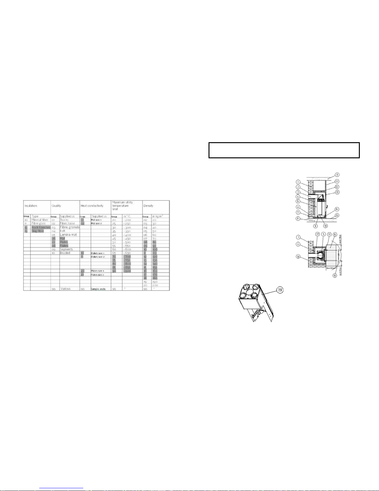
4.2 Heat insulation
Insulation must comprise heat insulation plates/elements of class A1 in accordance
with DIN 4102 part 1 with a utility temperature limit of 700 °C and a density of more
than 80 kg / m³. The insulation must be labelled in accordance with the relevant insulation code AGI Q 132.
Only the insulation materials given in the table below may be used. If other insulating
materials are used, they must be approved by the relevant supervisory bodies (e.g.:
Promat calcium silicate insulation plate ”Promasil 950 KS”, Wolfshöher insulation plate ”Prowolf” Wolfshöher insulation plate ”Vermilite 2000”, Thermax insulation plate
”Thermax SN 400”).
For protection of the building’s external walls and ceilings with a U-value of below 0.4
W / m², extra ventilation (see technical rules for stove and air source heating building
regulations) is required.
*divergent test conditions
The thermal insulation layers must be laid free of moisture and overlapping.
If the thermal insulating materials are to be used on replace inserts without a convection box, they must be wear-resistant and must not be covered with reective material
(e.g. with black plate, steel plate or galvanised steel). It is essential that the heat insulation has sucient temperature resistance (at least 700 °C), otherwise this can result in
unpleasant odours in the replace/insert.
36 37
5. Installation requirements
IMPORTANT:
The replace inset must not be in contact with the cabinet (min. distance 3 mm), as this
can damage the unit!
5.1. Installation in front of or to the side of a wall not to be protected
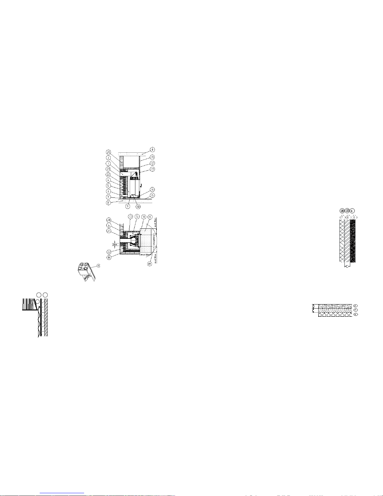
1 Second wall
2 Insulation layer (Flue)
3 Connection piece
4 Insulation layer (Back wall)
5 Convection space
6 Fresh air intake
7 Concrete plate min. 6 cm
(only when installing on a oor to be protected)
8 Ceiling
9 Insulation layer (Floor)
10 Combustion air pipe
11 Covering (Out towards the room)
12 Insulation layer (Ceiling)
13 Supply air grille
14 Circulation air grille
15 Protective shield for oors made of
non-ammable material
16 Insulation layer (Side wall)
17 Covering (Out towards the room)
18 80 cm radiation area
19 Convection box
Page 20
38 39
5.2. Installation in front of or to the side of a wall to be protected
2 Insulation layer (Flue)
3 Connection piece
4 Insulation layer (Back wall)
5 Convection space
6 Fresh air intake
7 Concrete plate min. 6 cm (only
when installing on a oor to be protected)
8 Ceiling
9 Insulation layer (Floor)
10 Combustion air pipe
11 Covering (Out towards the room)
12 Insulation layer (Ceiling)
13 Supply air grille
14 Circulation air grille
15 Protective shield for oors made of
non-ammable material
16 Insulation layer (Side wall)
17 Covering (Out towards the room)
18 80 cm radiation area
19 Convection air box
20 Wall to be protected
21 Fire protection at the ue lead-through
22 Front walling min. 10cm
5.3. Convection space
Without the convection box (accessory), there must be at least 6 cm
between the replace inset and insulation (4,16) at the back wall and
both sides.
• The convection areas (5) must have heat protection on all surfaces
that are not a heat-emitting lining.
• The replace walls, oor and ceiling must be clean and resistant to
wear (see professional rules for stove and air source heating technology). Otherwise, the insulation must be protected with a wear-resistant
material (radiation plate / replace inset plate etc.).
4
22
5
5.4. Heat insulation on the side and back wall
(All values in accordance with Promasil 950 KS)
• The front walling (22) and building’s wall (20) must be protected with a layer of insulation (4,16) to the back and side of the replace. Thermal insulation, see point 3 technical data.
• The lining (11) must also be protected with a layer of insulation. The lining does not
need to be protected when the replace is designed such that the temperature of the
lining’s free surfaces and niches for storing wood do not exceed max. 85° C. For surfaces made of mineral material, e.g. tiles, apart from where objects/things are to be
stored/place, a max. temperature of 120 °C applies instead of 85 °C. The rise in the
maximum permitted temperature from 85 °C to 120 °C applies only to more steep or
vertical surfaces of linings made from mineral material. This enables the lining such as
heat-emitting tile walls or similar to be extended.
5.5. Front walling
- There must be a 10 cm-thick (measurement C) mineral front walling (22), e.g. Poroton stone, between the insulation (4) and wall
(20). The front walling must extend at least 20 cm above the connection piece (3).
- Front walling (22) can be avoided if the wall (20) :
- is at least 10 cm thick and
- comprises non-ammable material and
- is not a supporting concrete or steel structure
5.6. Protecting the oor
- Floors (8) made of ammable material must be protected as follows:
- by a concrete plate (6) at least 6 cm (measurement E) thick, taking into account
the oor’s carrying capacity. An insulation layer (9) must be laid on top (measurement D). For insulation layers see point 3. - technical data.
- Supporting concrete or steel oors (8) must be protected as follows:
- Heat insulation layer (9) - min. thickness, see point 3 - technical data.
Convection air supply with convection box
All convection air supplies must be made from rigid, non-flammable material.
The hot air pipe must be secured to the supply air pipe and air grates (preferably with a
metal pipe).
Page 21
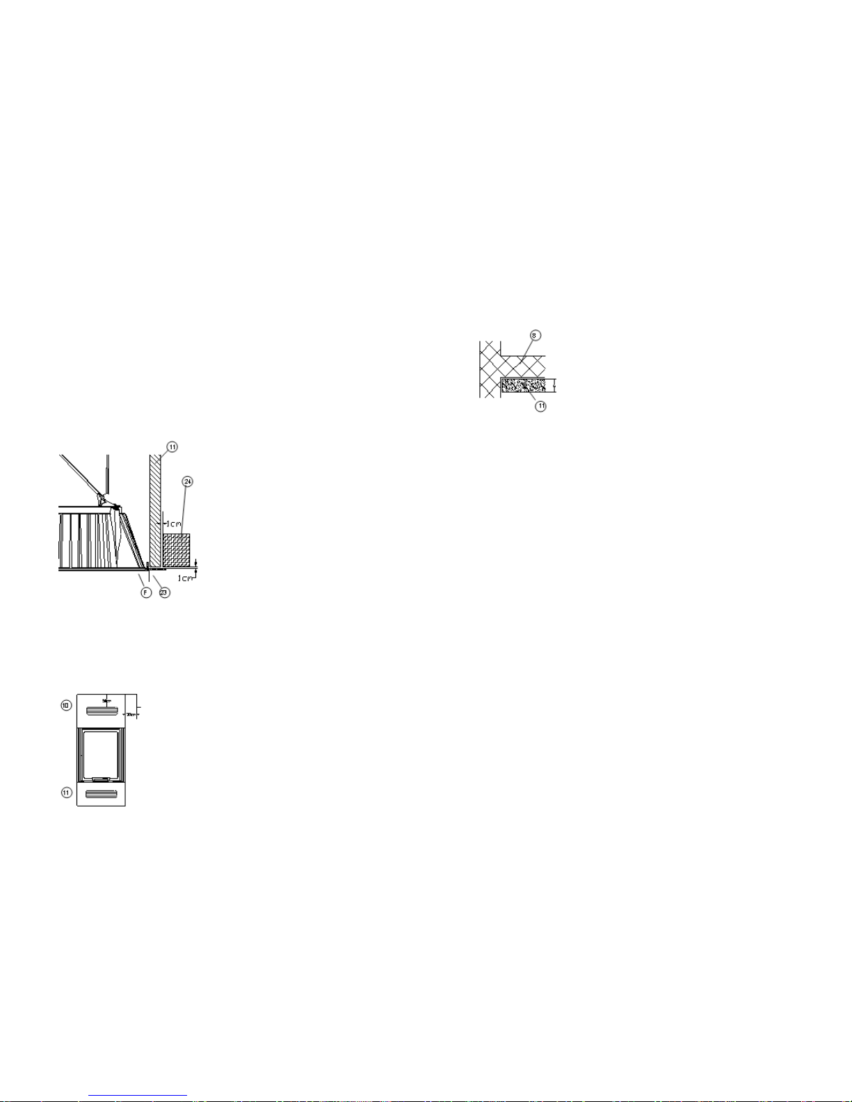
5.7. Expansion seams
- There must be NO contact/connection between the inset and the lining (11)! Therefore, all places of contact between the inset and lining must be shielded with a sealing
cord (Glass bre).
The support frame (23) must not rest on the insert or be screwed or welded to it!
5.8. Wall lining
- The lining room-side (11) must be made from non-ammable material to building material class A1, for example brick, ceramic chips, metal and plaster.
- Beams (24) in front of the lining (11) and support frame (23) next to the open replace are
permitted at a distance of at least 1 cm, when:
- the beams are not part of the building
- the clearance to the lining (11) is open enough
that heat does not accumulate
- the beams are not in the open replace’s radiation area.
- Direct fastening with heat bridges is not permitted.
5.9. Decorative beams
(F) Expansion joint (24) Beam
(23) Support frame (11) Lining
5.10. Chimney lining
- The chimney lining (11) must not be in direct contact with the replace insert. It must
be self-supporting. The manufacturers oer various support frames for this purpose
(23).
5.11. Convection air supply
- The cross-section of the air inlet (14) and air outlet guide
must each be at least 700 cm².
- It must not be possible to close off at least 200 cm² of the air
inlet and air outlet opening.
- There must not be any flammable building material, e.g.
wood ceiling or furniture, within a distance of 30 cm of the side
of the air outlet and 50 cm above the air outlet (13).
40 41
5.12. Ceiling above the Insert
- If the cavity above the replace inset reaches up to the ceiling
(8), it must be protected, if:
- it consists of ammable material,
- there is a supporting element in the building.
Insulation (G) must be installed to local/national requirements/
standards (11).
5.13. Floor in front of the inset
- The oor in front of the inset must comprise a non-ammable material. The minimum
dimension for the area is:
In front:
- the distance between the oor and lower edge of the combustion chamber plus 30
cm, however at least 50 cm.
To the sides:
- the distance between the oor and lower edge of the combustion chamber plus 30
cm, however at least 30 cm.
5.14. Fire safety in the radiation area
- There must be a safety distance to ammable material on each side of and above the
inset’s door of at least 80 cm. If ventilated radiation protection is present on each side, a
distance of 40 cm is enough.
5.15. Fire safety outside the radiation area
There must be a distance of at least 5 cm between the inset’s outer wall and ammable
material such as furniture or other ammable materials. There must be sucient odour
ow-through in this gap to prevent any unpleasant odours. Building materials that comprise only a small part of the inset’s lining, such as oor, wall lining,
and insulation on the ceiling/walls, can be tted directly around the inset’s lining.
5.16. Electrical cables
The walls and ceiling near to the inset must not contain electrical wires!
Page 22
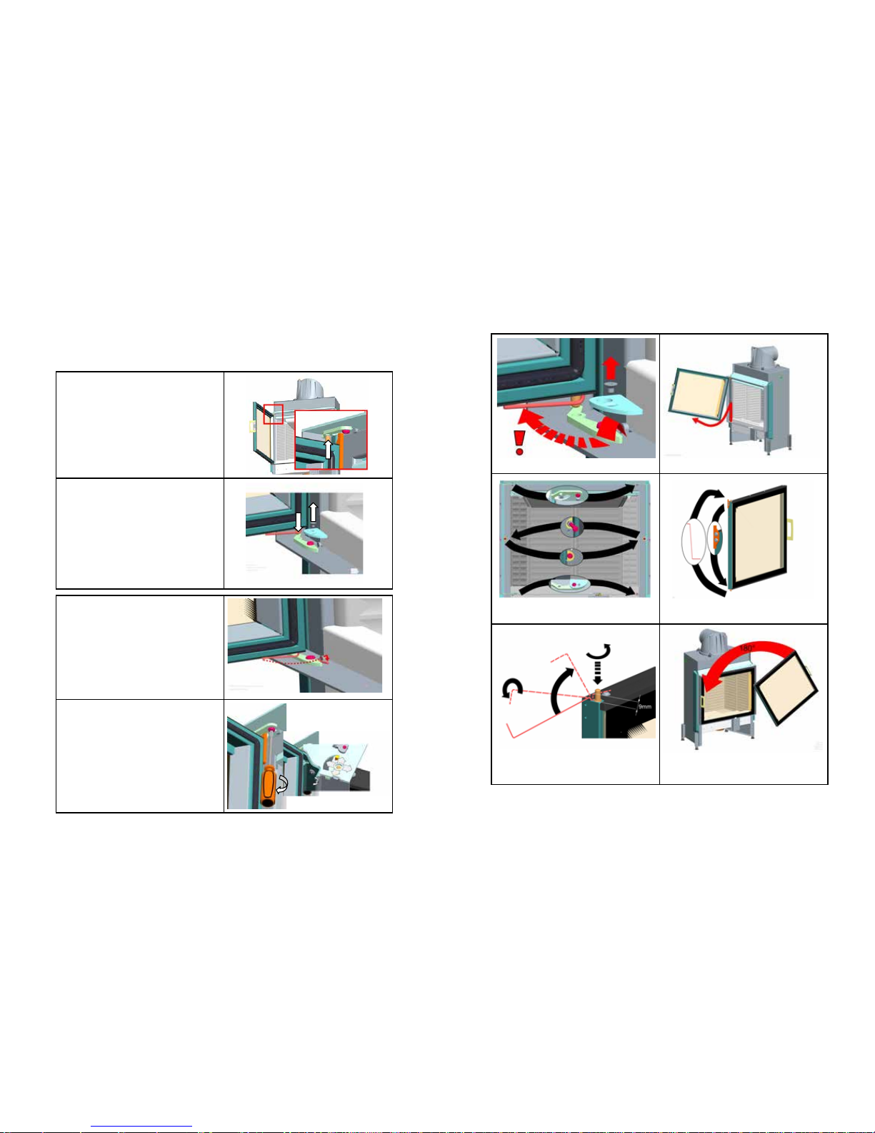
6. Information on maintenance/repair
6.1. Folding door inset - Fitting the door
1. Fit the door in the open position
2. First hang the door in front of the stove push the top bolt into the opening.
3. This allows the door’s bottom pin slide
into the bottom seat.
4. Remove the box screw and plate.
5. Finally tighten the spring until it clicks
into place behind the hinge.
6. Loosen the screw and push it to either
side to adjust the angle of the door if it
is going to hang. You can also adjust the
pressure from the sealing strip. Finally retighten the screw.
42 43
Converting the opening from right to left-sided
Remove the spring Lift o the door
Swap over the screws and hinges etc. Fit the spring and doorstop on the other
side
The spring clicks into place and the bolt
can easily be re-tightened. There must be
9 mm clearance!
The door can now be rotaded 180° and
tted.
Page 23
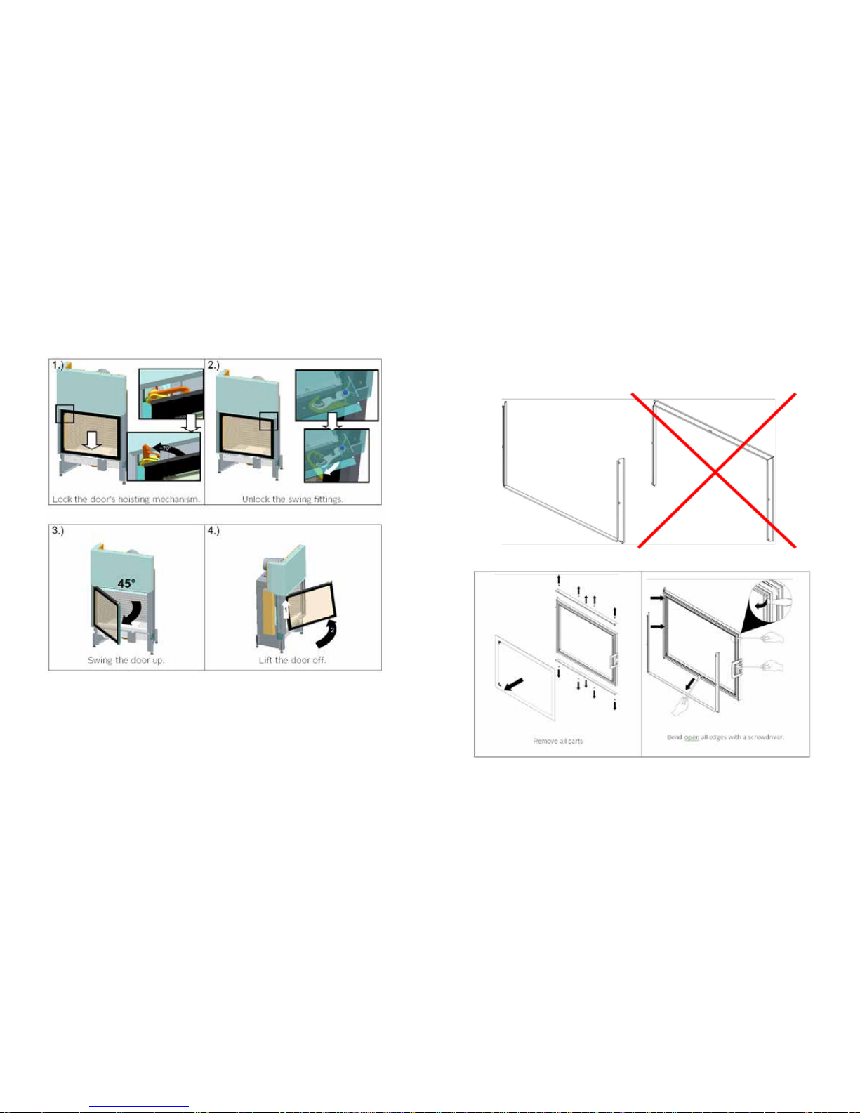
6.2. Sliding door inserts - Fitting the door
(Fitting the door in the reverse order)
6.3 Converting the radiation frame to right opening of the door
IMPORTANT: The radiation frame must be rotaded 180° in the door (the horizontal part
must always be at the bottom), otherwise this can aect the secondary air supply, which
impars combustion and can cause soot to form on the glass
For replace insets S100, S101, S120, S121 and S122
44 45
Page 24
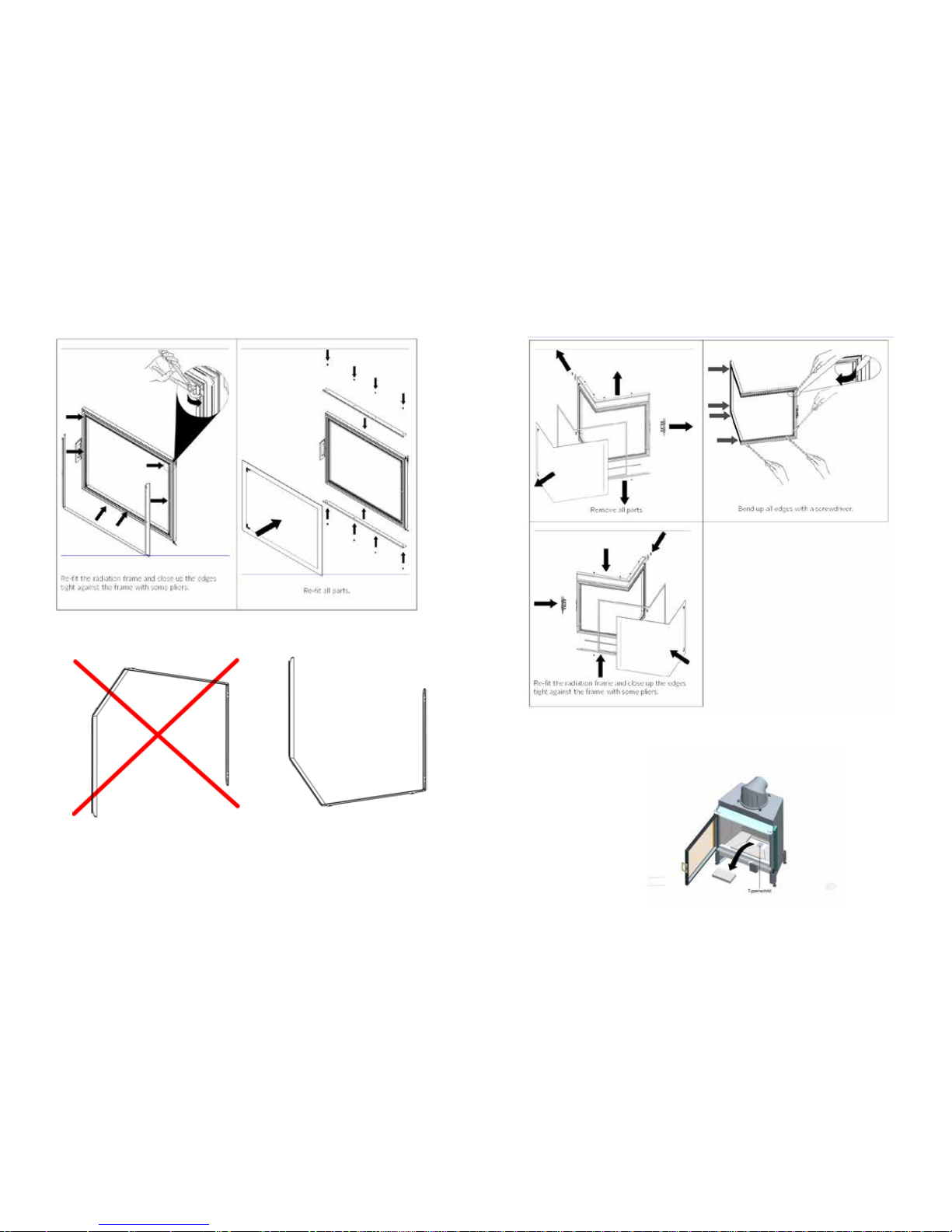
For insert Morsø S140
46 47
6.3. Type plate location
The type plate can be found under the middle stone in the base of the stove (or under the ash drawer).
Page 25
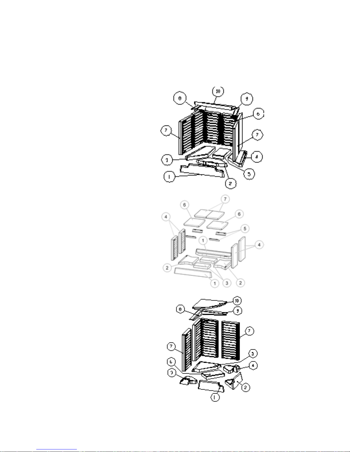
6.4. Combustion
Place the chamotte parts without mortar in the order illustrated
For models:
S100 and S101
1. Log catch
2. Base front
3. Base left
4. Base right
5. Intermediate plate
6. Back wall
7. Side wall
8. Z-plate left
9. Z-plate right
10. Flue plate
S120, S121 and S122
1. Log catch
2. Base
3. Intermediate plate
4. Side wall
5. Support angle
6. Flue plate (245)
7. Flue plate (195)
S140
8. Log catch left
9. Log catch right
10. Base left
11. Base right
12. Base back
13. Intermediate plate
14. Side wall
15. Z-plate left
16. Z-plate right
17. Flue plate
Morsø Jernstøberi A/S - 15.04.2015
 Loading...