

Page 1
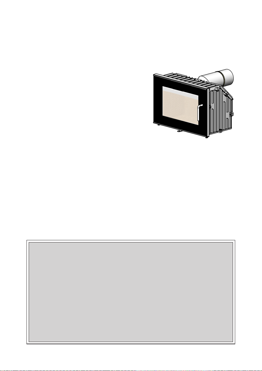
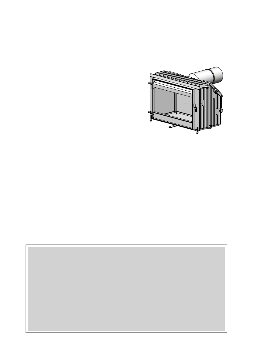
Morsø 5660M
DK Opstillings- og betjeningsvejledning
UK Instructions for installation and use
MORSØ JERNSTØBERI A/S . DK-7900 NYKØBING MORS
E-Mail: [email protected] · Website: www.morsoe.com
Page 2

INDHOLD CONTENTS
DK 1.0 Opstilling af Deres Morsø ovn. .. .. .. .. .. .. .. .. .. .. .. ..5
2.0 Fyringsteknik/Brugen af Deres ovn . .. .. .. .. .. .. .. 15
3.0 Regelmæssig vedligeholdelse af ovnen. .. .. .. .. .. 19
4.0 Tekniske data . .. .. .. .. .. .. .. .. .. .. .. .. .. .. .. .. .. .. .. .. .. 21
UK 1.0 Installing your Morsø stove .. .. .. .. .. .. .. .. .. .. .. .. ..24
2.0 Firing/using the stove .. .. .. .. .. .. .. .. .. .. .. .. .. .. .. .. 34
3.0 Routine stove maintenance.. .. .. .. .. .. .. .. .. .. .. .. ..38
4.0 HETAS amendments .. .. .. .. .. .. .. .. .. .. .. .. .. .. .. .. ..40
2
Page 3
Opstillings- og betjeningsvejledning
5660M
EN 13240 · NS 3058-3059
MORSØ JERNSTØBERI A/S . DK-7900 NYKØBING MORS
E-Mail: [email protected] · Website: www.morsoe.com
3
Page 4

Til lykke med Deres nye Morsø ovn!
Morsø, som er den største udbyder på det danske
marked, har siden 1853 fremstillet brændeovne
af den højeste kvalitet. Hvis De blot følger omstående instruktioner, er vi sikre på, at De også vil få
nytte og glæde af Deres nye ovn i mange år.
Indhold
1.0 Opstilling af Deres Morsø ovn Side nr.
1.1 Udpakning af ovnen 5
1.2 Opstilling af ovnen 5
1.3 Skorstensfejer 5
1.4 Ovnens placering/Afstandskrav 7
1.5 Skorstenen 12
1.6 Tilslutning til muret skorsten 13
1.7 Tilslutning til stålskorsten 13
1.8 Trækforhold 14
2.0 Fyringsteknik 15
2.1 Optænding og fyringsintervaller 16
3.0 Regelmæssig vedligeholdelse af ovnen 19
3.1 Udvendig vedligeholdelse 19
3.2 Indvendig vedligeholdelse 19
4.0 Tekniske data 21
Prøvningsattest - skal følge ovnen
Den dans ke Brændeovn sbekendgørel se trådte ikr aft den 1. janua r 2008. I forbi ndelse med ind førelsen
af Bræn deovnsbeken dgørelsen er de t et krav, at der med br ændeovnen føl ger en prøvning sattest , der
er udstedt af det akkrediterede prøvningsinstitut, der har udført miljøafprøvningen på ovnen.
Prøvningsattesten er vedlagt i ovnen og skal opbevares af ejeren og følge ovnen i ovnens levetid.
Efter installation af brændeovnen og godkendelse af en skorstensfejer skal skorstensfejeren underskrive prøvningsattesten som dokumentation på, at ovnen opfylder miljøkravene
i henhold til Brændeovnsbekendgørelsen.
Ekstra tilbehør
Til Morsø ovnene tilbydes et omfattende skorstens-, gulvplade- og tilbehørsprogram, der
kan lette den daglige betjening og vedligeholdelse af Deres Morsø ovn.
Støbejern
Støbejern er et levende materiale. Der er derfor ikke to ovne, der er helt ens. Det skyldes
dels tolerancerne på støbejern, dels at ovnene er håndværksmæssigt udført.
I støbejernets overade kan der ligeledes forekomme mindre ujævnheder.
4
Page 5

1.0 Opstilling af Deres Morsø Ovn
1.1 Udpakning af ovnen
Det anbefales at være to mand til dette arbejde, da ovnen er tung at håndtere ene.
MORSØ 5660M vejer ca. 125 kg.
Emballagen fra ovnen kan bortskaes efter gældende regler om renovation.
Ovnen er egnet til intermitterende brug.
1.2 Opstilling af ovnen
Man skal være opmærksom på nationale og lokale bestemmelser vedrørende opstilling af
brændeovne. Samtidig skal man følge de lokale bestemmelser med hensyn til tilslutning til
skorsten samt opstilling af skorstene. Spørg evt. Deres skorstensfejer til råds. Det er dog
Dem selv, Deres tekniske rådgiver eller håndværker, der er ansvarlig for, at de nationale og
lokale bestemmelser overholdes.
1.3 Skorstensfejer
Det kan, som nævnt, være klogt at rådføre sig med den lokale skorstensfejer inden opstilling
af ovnen. Under alle omstændigheder skal skorstensfejeren underrettes, når brændeovnen
er opstillet. Skorstensfejeren foretager et check af installationen, og der aftales fejningsterminer. Hvis skorstenen ikke har været i brug i nogen tid, bør den undersøges for revnedannelser, fuglereder m.v., inden den igen tages i brug.
5
Page 6
Montering
SECTION
SCALE
1 : 12
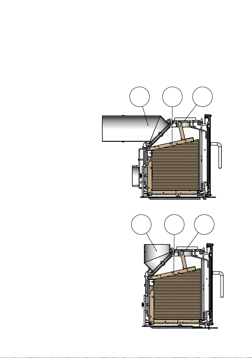
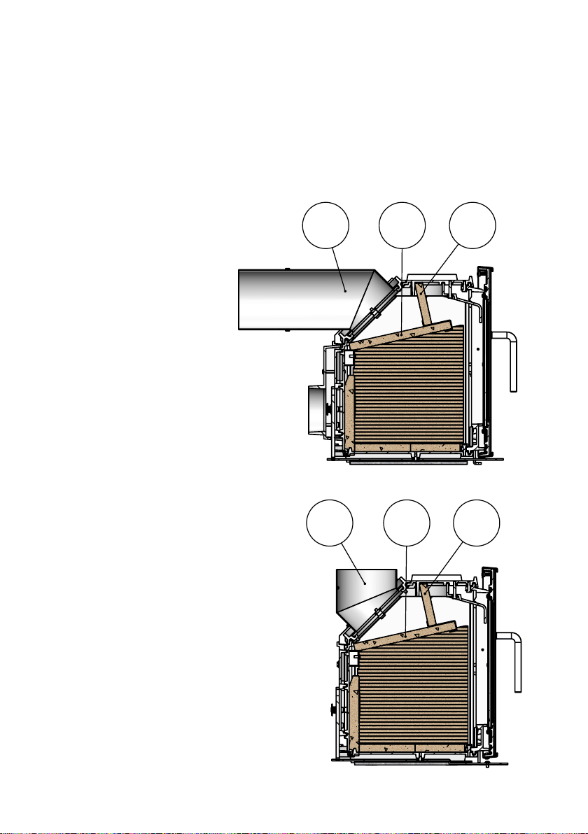
Til Morsø 5660M ovnen skal der tilsluttes en 45° rørbøjning (1),enten en rørbøjning til
topafgang eller en anden rørbøjning til bagafgang.
Placering af røgledeplader
Røgledepladerne (2) og (3), der er udført i vermiculite, er placeret ved modtagelsen.
Man skal sikre sig, at røgledepladerne er korrekt monteret inden en optænding af ovnen
nder sted (se skitse).
Bagudgang
Topudgang
321
1 2 3
6
Page 7
1.4 Ovnens placering/Afstandskrav.
Indbygning i Morsø modulsystem.
Indsatsovnen Morsø 5660M er beregnet til indbygning i Morsø indsats modulsystem.
Modulsystemet består af 3 modul typer:
• Modul til indsats Morsø 5660M
• Modul til placering under indsatsen
• Side moduler
De tilstødende materialer skal være ubrændbare.
Et lag tapet bliver normalt, når det er påsat murværk, betragtet som ikke-brændbart
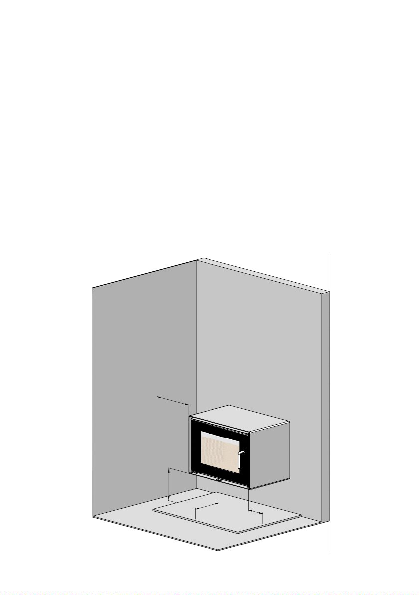
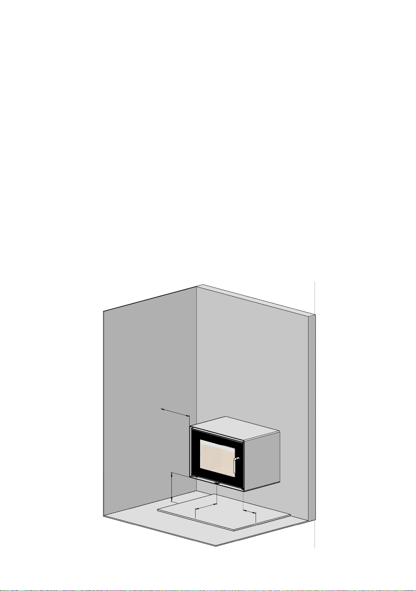
materiale. Et ikke brændbart underlag skal dække gulvet mindst 300 mm. foran fyrdøren, og
mindst 150 mm. til hver side foran fyråbningen.
Vær opmærksom på at gulvet skal kunne bære installationen. Ligeledes hvis Morsø 5660M
ophænges på væg skal man sikre sig at væggen kan bære installationen
Kun når ovnen placeres op ad brændbart materiale, stilles der krav til afstand.
Der er følgende afstandskrav.
Møbleringsafstand 1300 mm
Afstand til 90° brændbar sidevæg fra ovn 400* mm
Højde over brændbar gulv, minimum 300** mm
400*
300**
300
150
7
Page 8
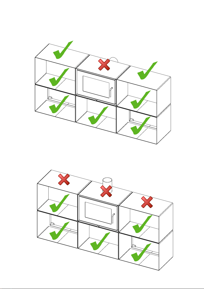
Eksempel på Morsø 5660M modulsystem med bagudgang.
På ader der er markeret med ueben må der stilles brændbare materialer.
På ader markeret med et kryds må der ikke stilles brændbare materialer
Eksempel på Morsø 5660M modulsystem med topafgang.
På ader der er markeret med ueben må der stilles brændbare materialer.
På ader markeret med et kryds må der ikke stilles brændbare materialer
8
Page 9
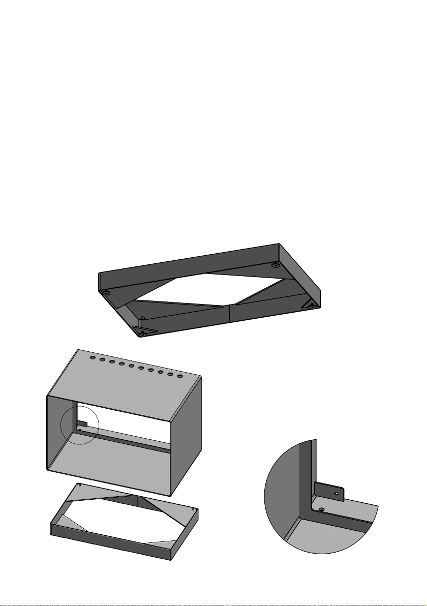
Montering af Morsø 5660M
B
B
B
Til modulsystemet er der 4 forskellige kabinetter/moduler.
-1 modul til brændkammeret med røgafgang bagud
-1 modul til brændkammeret med røgafgang ovenud
-1 modul til placering under ovnen
-1 modul til placering ved ovnens sider
-1 sokkel.
-1 røgrør til bagudgang
-1 røgrør til topudgang
Placering / montering af Morsø 5660M
Det anbefales at være 2 personer til monteringen for at undgå skamferinger.
Ønskes kabinetterne væghængt anvendes de vedlagte vægbeslag. Man skal sikre sig, at
væggen og boltene, der anvendes, kan holde ovnen og modulerne. Til orientering vejer et
modul med ovnen monteret 195kg, mens et løst modul vejer 57kg.
Hænges ovnen alene op på væggen, skal man være opmærksom på, at den mindste
afstand til undersiden af modulet minimum skal være 300mm fra gulvet, hvis gulvet er
udført i brændbart materiale.
Ønskes ovnen monteret med et modul under ovnen, skrues de to medfølgende bolte og
de re stilleskruer i soklen som placeres på gulvet der, hvor ovnen skal have sin endelige
placering.
A
Soklen justeres i vater med stilleskruerne.
Herefter placeres det modul, der med sine
huller placeret bagerst på oversiden af modulet på soklen, så de to huller bagerst i bunden
af modulet rammer ned over boltene på
soklen (se skitse A og B). Soklen og modulet
skrues sammen med de medfølgende skiver
og møtrikker (se skitse C).
A
9
Page 10
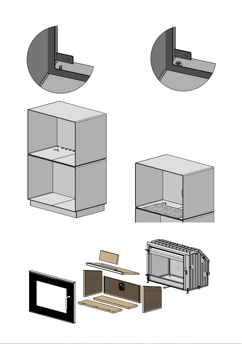
C
C
321
SECTION
C-C
SCALE
1 : 12
1 2 3
SECTION
B-B
SCALE
1 : 12
321
SECTION
SCALE
1 : 12
C-C
SCALE
1 : 12
1 2 3
B
Herefter løftes modulet, forberedt til montering
af ovnen, på plads. Sørg for at de to Ø10 huller bagerst i modulet er lige over Ø10 hullerne i modulet
under. Placer de to vedlagte M8x16 bolte i Ø10
hullerne, så de går gennem begge moduler.
Inden placering af ovnen monteres stål bagpladen
med de vedlagte magneter.
Den medfølgende glideplade lægges i bunden af
modulet og skubbes ind til stoåndet rammer
kanten af modulet.
C
Døren afmonteres ovnen og vermiculite pladerne tages ud og start med den øverste
lodrette plade.
10
Page 11
321
SECTION
C-C
SCALE
1 : 12
1 2 3
SECTION
C-C
SCALE
1 : 12
1 2 3
300**
400*
B-B
1 : 12
321
SECTION
C-C
SCALE
1 : 12
SECTION
B-B
SCALE
1 : 12
321
SECTION
C-C
SCALE
1 : 12
1 2 3
321
SECTION
C-C
SCALE
1 : 12
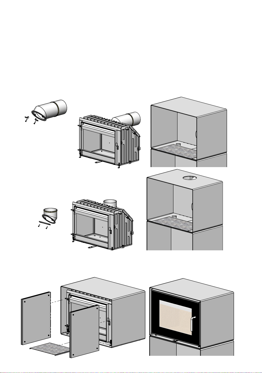
OBS! VED MONTAGE AF OVNEN MED TOPUDGANG KAN RØGRØRET IKKE MONTERES
FØR OVNEN INDSÆTTES I MODULET.
Som tidligere nævnt på side 5 skal der bruges 2 personer til at installere ovnen, da røgrøret
skal løftet op igennem topudgangen, mens ovnen indsættes i modulet, og først derefter
kan røgrøret skrues på ovnen.
Røgrøret monteres på ovnen. Ovnen løftes ind på glidepladen og kan på glidepladen skubbes helt ind på plads uden at ridse modulet. Ovnen justeres i vater med de monterede stille sk ruer. Glidepladen skal ikke bruges mere og kan ernes ved at løfte ovnen lidt foran. De
to beslag nederst på forrammen løsnes, så de glider ned og rammer bunden i modulet og
spændes fast igen. Dette gør at ovnen ikke vipper når døren åbnes.
Bemærk: Ved bagudgang skal kulespærre ikke anvendes.
Bagudgang
Topudgang
Nu placeres den underste stråleskærm løst under brændkammeret og de 2x3 stråleplader,
der modtages samlet, placeres løst, et sæt i hver side (se skitse) uden at skubbes dem helt
tilbage imod bagpladen i modulet. Endelig isættes vermiculite pladerne igen og slut med
den øverste lodrette plade. Til sidst monteres døren igen.
11
Page 12
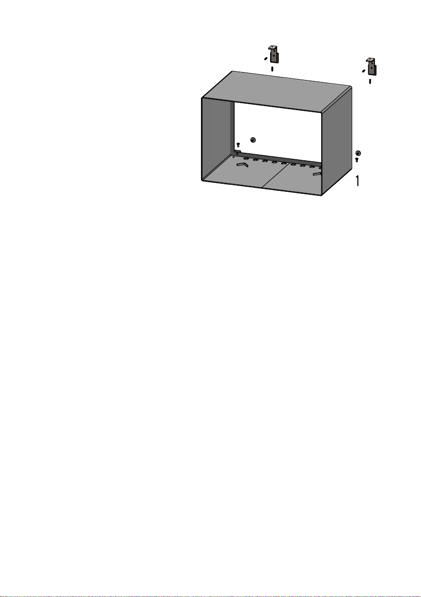
Foretages monteringen væghængt
kan modulerne justeres i vater med de
medfølgende stilleskruer og stillefødder
med den medfølgende unbraco nøgle (se
sk its e).
Når ovnmonteringen og røgrørsføringen
er afsluttet fortsættes med en eventuel
videre montering af moduler på siderne.
Bemærk, af sikkerhedsmæssige årsager,
må der ikke monteres et modul over
brændkammermodulet.
Møbleringsafstand
Den anbefalede møbleringsafstand er 1300 mm, men man bør dog vurdere, om møbler og
andet vil blive udtørret af at stå tæt på ovnen.
Afstand til brændbart materiale foran ovnen er 1300 mm.
En brændeovn bliver varm under fyring. Der skal derfor udvises en fornøden forsigtighed,
specielt i.f.m. børns kontakt med ovnen.
Ovnen er udstyret med et aftageligt håndtag i rustfrit stål - et materiale der leder varmen
dårligt. Når håndtaget er ernet, er ovnen samtidig mere børnesikker.
1.5 Skorstenen
Hvis lokale bestemmelser tillader det, kan ovnen tilsluttes en skorsten, hvortil der i forvejen
er tilsluttet et andet lukket ildsted ( f.eks. en anden brændeovn eller oliefyr ). Men bemærk
at en brændeovn ikke må tilsluttes samme skorsten som nye kondenserende oliefyr. Er De i
tvivl bedes De kontakte Deres skorstensfejer.
Man skal være opmærksom på eventuelle krav til placering af røgrør, hvis to eller ere ildsteder tilsluttes samme skorsten.
Brændeovnen må aldrig tilsluttes en skorsten, hvor et gasfyr er tilsluttet.
En moderne eektiv ovn stiller større krav til Deres skorsten. Lad derfor skorstensfejeren
vurdere skorstenen.
Skorstenens lysning skal følge de nationale og lokale bestemmelser. Men generelt bør lysningsarealet mindst være 175 cm2 (150 mm diameter ) for brændeovne.
En for stor skorstenslysning bevirker, at der bruges for meget energi på at få opvarmet skorstenen til et acceptabelt træk. Er der tale om en muret skorsten med større lysning, anbefales
det at isætte en isolerende skorstensforing med den rigtige diameter. Herved opnås et forøget træk og tillige en bedre fyringsøkonomi.
Der stilles ingen krav til nogen bestemt skorstenshøjde, men den skal være så høj, at trækforholdene er i orden og røgen ikke generer. Som hovedregel er trækforholdene tilfredsstillende, når skorstenen er 4 meter over ovnen og er ført mindst 80 cm over tagrygningen. Placeres skorstenen ved husets sider bør toppen af skorstenen aldrig være lavere end
husets tagryg eller tagets højeste punkt. Bemærk, at der ofte gælder nationale og lokale
bestemmelser med hensyn til placering af skorstene i forbindelse med stråtag. Se afsnittet
trækforhold 1.9.
12
Page 13
Skorsten og røgrør skal forsynes med renselemme. Størrelsen på renselemme i skorsten skal
mindst svare til skorstenens lysningsareal.
Skorstenen skal være tilgængelig for udvendigt eftersyn, og der skal være mulighed for
adgang til renselemme og til skorstenen, hvis den skal renses fra toppen (eks. stålskorstene).
1.6 Tilslutning til muret skorsten
I den murede skorsten fastmures en røgrørsbøsning,
og det medfølgende bånd tapes på røgrøret ca. 12 cm
inde på røret. Røret må ikke stikkes ind i selve skorstensåbningen, men kun gå til den indvendige side af
skorstenslysningen. Normalt behøver man ikke tætne
mellem evt. rørsamlinger.
Evt. overgang fra lodret til vandret røgrør kan med
fordel monteres med en blød bøjning for at undgå
tab af skorstenstræk.
Dimensioneringen af røgrør skal følge de nationale
og lokale bestemmelser. Morsø anbefaler dog, at
røgrør udføres i 2 mm stålplade, da det vil forlænge
røgrørets levetid.
1.7 Tilslutning til stålskorsten
Er der tale om opstilling, hvor skorstenen føres direkte op gennem loftet, skal man følge de
nationale og lokale bestemmelser m.h.t. skorstenens afstand til brandbart loft. Skorstenen
tætnes ved røgtuden med glassnor. Det er vigtigt at skorstenen er monteret med tagbæring eller loftkrave med styr. (Se skorstensfabrikantens vejledning). En stor vægt på ovnens
topplade kan forårsage revnedannelse af denne.
Morsøs garanti omfatter ikke toppladen, hvis skorstenen er monteret uden tagbæring, tagstyr eller lignende.
Skulle der opstå skorstensbrand i.f.m. fejlbetjening af ovnen eller længere tids anvendelse
af fugtigt brændsel, lukkes spjældet helt, og brandvæsnet kontaktes.
Vær opmærksom på!
Rensningsmuligheder. Tal med skorstensfejeren.
Undgå ere bøjninger end nødvendigt og begræns røgrørslængden, da trækforholdene ellers nedsættes.
Frisklufttilførsel
En brændeovn kræver luft til forbrændingen. Dette bevirker, at brændeovnsfyring
er med til at give et sundt indeklima i et hus. Hvis huset er meget tæt, og især hvis
der er emhætte eller ventilationsanlæg i huset, kan det være nødvendigt at anbringe en luftrist i det rum, hvor brændeovnen er opstillet. I modsat fald vil skorstenstrækket blive for svagt, hvilket kan medføre at ovnen ikke vil brænde ordentligt , og
der kan komme røg ud af ovnen når fyrdøren åbnes.
Er det nødvendigt at anbringe luftriste, skal de placeres således, at de ikke kan
blokeres.
13
Page 14

1.8 Trækforhold
Hvis der kommer røg ud af ovnen, når fyrdøren åbnes, skyldes det dårligt skortstenstræk.
Der kræves et skorstenstræk på mindst 12 pa. for at afgive tilfredsstillende forbrænding og
forhindre røgudslip. Der vil dog være risiko for røgudslip, hvis ovndøren åbnes under meget
kraftig fyring.
Røggastemperaturen ved nominel ydelse er 241°C henført til 20°C.
Røggasmasseowet er 6,8gr./sek.
Er De i tvivl, kan De eventuelt lade Deres skorstensfejer måle trækket i skorstenen.
Trækforhold
Skorstenens træk skabes på grund af forskellen mellem den høje temperatur i skorstenen og den koldere udetemperatur. Skorstenens længde og isolering, vind og vejrforhold er også afgørende for, at man kan opnå det rette undertryk, så trækket skabes.
14
Nedsat træk fremkommer når:
- Temperaturforskellen er for lille. Eksempelvis ved for dårlig isoleret skorsten.
Hvis skorstenen er kold, kan det inden optænding hjælpe at antænde (alus-
se) en sammenkrøllet avis i skorstenens rensedør.
- Udetemperaturen er for høj. Eksempelvis om sommeren.
- Det er vindstille.
- Skorstenen ikke har den rette højde, så den er i læ af tagade og høje træer. I
disse tilfælde er der også størst risiko for røgnedslag.
- Der kommer falsk luft ind i skorstenen. Eksempelvis gennem manglende fuger
eller utætheder ved renselem eller røgrør.
- Der er utætte ubenyttede ildsteder tilsluttet skorstenen.
- Røgrør og skorsten er tilstoppet af sod p.g.a. manglende rensning.
- Huset er for tæt (se afsnittet: Frisklufttilførsel).
Godt træk fremkommer når:
- Temperaturforskellen i skorstenen og udenfor er stor. Altså ved fyring, når
behovet er størst.
- Det er klart i vejret og der er en god vind.
- Skorstenen har den rette højde. Min. 4 meter over ovnen og fri af tagryg.
Page 15

2.0 Fyringsteknik/Brugen af Deres ovn
Ovnens varmeafgivelse reguleres med reguleringshåndtaget under lågen.
Ovnen har 3 typer forbrændi ngsluft. Sekundær for brændingsluft der t ilføres ned lang s glasset. D enne
luft reguleres af håndtaget under lågen. Tertiær forbrændingsluft der tilføres forbrændingen lige over
bålet. Denne lufttilførsel kan ikke reguleres. Pilot forbrændingsluft som sørger for at aktivere gløder
og holde forbrændingen i gang, selv under laveste spjæld indstilling. Denne lufttilførsel kommer fra to
dyser på forrammen nederst bag lågen. Denne lufttilførsel kan ikke reguleres.
Ovnens nominelle varmeydelse er 7,3kW.
Deres nye Morsø ovn er EN afprøvet og anbefalet til fyring med træ.
VIGTIGT!
Træ er et yderst gasholdigt materiale (ca. 75 %). Disse gasser frigives under opvarmning og antændelse af træet. Det er derfor vigtigt at disse gasser antændes hurtigt efter en påfyldning. Ligger træet kun og ulmer, specielt efter en ny
påfyldning, giver det en kraftig røgudvikling, som i værste fald kan forårsage en
eksplosionsagtig antændelse af gasserne med skader på ovnen til følge.
For at kunne antænde disse frigivne gasser fra træet og opretholde klare og blivende ammer i forbrændingsforløbet, er det derfor vigtigt altid at tilføre den
nødvendige mængde ilt (luftmængde).
Indstilling af lufttilførsel, optændingsmetode og fyringsintervaller er aængig
af skorstenstræk, vind- og vejrforhold, varmebehov, brændsel m.m. Derfor kan
der gå tid, inden De kender ovnens korrekte funktion under de givne forhold.
Selv om der kan fyres med næsten alle former for træ i Deres Morsø ovn, skal man ikke
fyre med vådt eller ulagret træ. Træ bør under tag lagres mindst 1 år og helst 2 år med fri
adgang for vind. Træ skal kløves hurtigst mulig t efter fældningen, hvis det skal tørre hurtigt. Træet kan anvendes, når fugtigheden er under 20%. Under EN afprøvningen testes
alle brændeovne med træ der har et fugtindhold på (16 ± 4)%.
Brug aldrig drivtømmer, da det som regel er meget saltholdigt, og ødelægger dermed både ovnen og skorsten. Imprægneret og malet træ samt spånplader udsender giftig røg og dampe og må derfor heller ikke anvendes som brænde.
Bemærk, der må ikke anvendes ydende brændsel i ovnen.
Brændestykker med en diameter større end 10 cm bør altid kløves. Brændestykkerne må ikke være længere, end de kan ligge plant over glødelaget med luft til
begge ender. Maximal brændelængde i ovnen er 30 cm.
Maximal brændemængde er ca 2 kg./time (max. 2 stykker træ pr. påfyldning).
De første optændinger skal være moderate, således at den varmebestandige maling kan hærdes, inden der fyres kraftigere. Malingen kan i hærdningsfasen udvikle røg og lugtgener under den første optænding, hvilket er ganske normalt. Sørg
derfor for udluftning i denne periode.
Under opvarmning og nedkøling kan ovnen afgive nogle knirkelyde, hvilket skyldes den store temperaturforskel materialet udsættes for.
15
Page 16
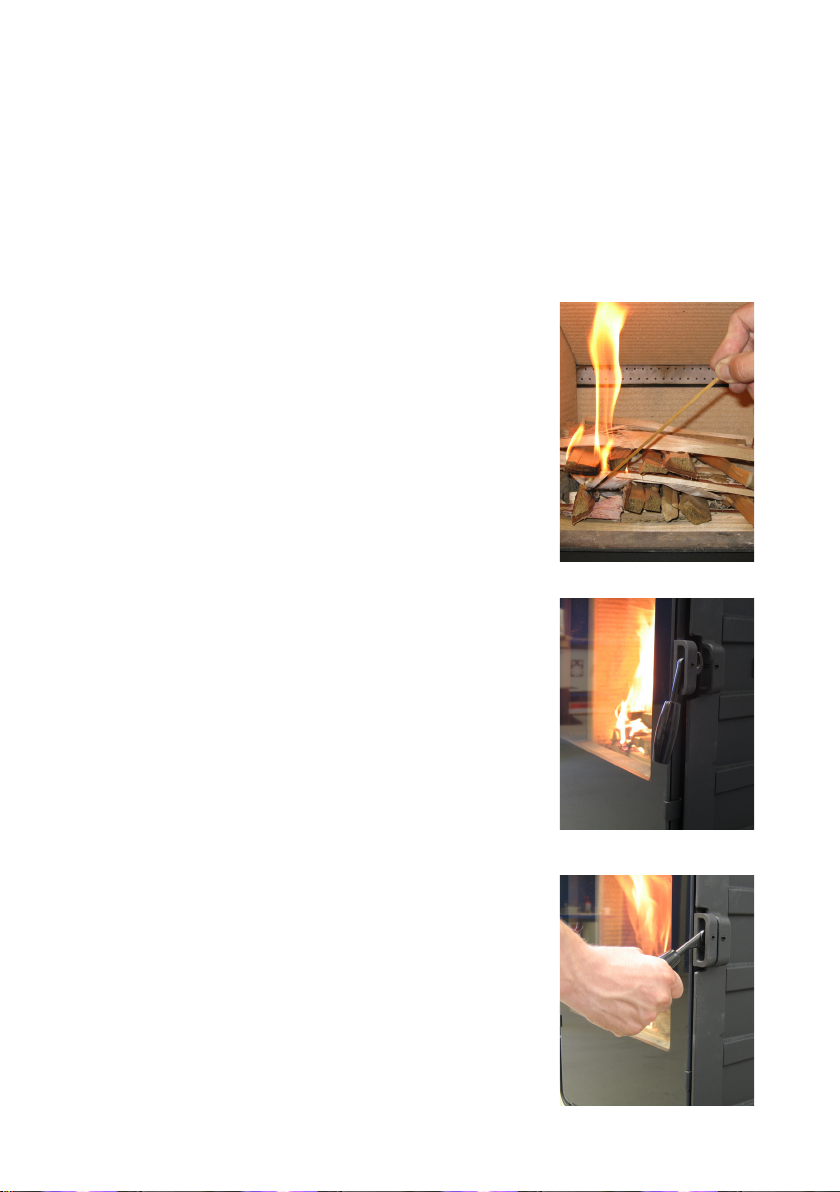
2.1 Optænding og fyringsintervaller
Under optænding er der behov for en stor luftmængde. Startes der op med en helt kold ovn,
kan man med fordel lade døren stå på klem de første minutter.
For at opbygge et isolerende askelag i bunden af ovnen, bør De ved første optænding afbrænde ca. 3 kg tørt pindebrænde. Behold herefter altid ca. 1 cm aske i bunden af brændkammeret.
1. Det anbefales, at man benytter „Top-Down“-optænding, når man tænder op i brændeovnen. Det er den mest
miljøvenlige optændingsmetode. Glødelaget dannes hurtigt
ved optænding med 2-4 optændingsposer samt ca. 3-4 kg
tørt pindebrænde. Optændingsposerne anbringes lige under
det øverste lag pindebrænde.
Det er vigtigt at starte forsigtigt op, så forbrændingen langsomt opbygges. Dermed minimerer man soddannelse på
glasset. Soddannelse på glas skyldes ofte for kraftig fyring
mod kolde overader. Undgår man soddannelse under optændingen og får opbygget et varmt glødelag, vil efterfølgende
indfyringer have minimal soddannelse.
2. Der åbnes helt for sekundærluften vha reguleringshåndtaget.
3. Efter antænding lukkes fyrdøren på klem, så der er godt
med træk ved en åbning på ca. 2 cm.
4. Når man kan se (efter 5-10 min.), at skorstenen er så varm, at
der er træk igennem den, lukkes døren helt. Hvis alle forudsætninger er opfyldt, vil der efter yderligere ca. 15-20 min. være
dannet et pænt glødelag i brandkammeret.
16
Page 17

5. Normal påfyring bør ske, mens der endnu er gløder tilbage.
Fordel gløderne i bunden, dog est foran i ovnen.
6. Der lægges 2-3 stykker brænde à ca. 0,7-1 kg og 30-50 cm
lange ind over gløderne i ét lag med en afstand på ca. 1 cm mellem træ-stykkerne. Bedste forbrænding opnås hvis kævlernes
længderetning er parallel med ovnens bagvæg.
7. Når den sekundære lufttilførsel er åbnet på max. og døren
lukkes, vil den friske træ mængde være antændt på et par minu tter.
Vigtigt!
Det er vigtigt, at den friske træmængde hurtigt begynder at brænde. En hurtig antændelse af brændet opnås ved at åbne forbrændingsluften på max. eller ved at
lade døren stå på klem for at tilføre den mængde luft,
der skal til for at antænde træet.
Hvis brændet derimod kun ulmer, giver det en kraftig
røgudvikling, som i værste fald kan forårsage en eksplosionsagtig antændelse af røggasserne med risiko for såvel materielle skader som personskader.
8. Herefter justeres den sekundære luftmængde ned til den
ønskede position, og den optimale forbrænding vil fortsætte til
grundglød.
Man skal sikre sig, at der altid er luft (ilt) nok til at opretholde klare og blivende ammer under og efter nedjustering
af forbrændingsluften.
Under den nominelle afprøvning lå påfyld-ningsintervallet på
60-70 minutter.
9. En ny portion træ kan påfyres på samme måde som angivet
i pkt. 5 & 6.
17
Page 18

Normalt skal ovndøren altid åbnes roligt de første 2-3 centimeter, og man skal vente til trykket er udlignet inden døren åbnes helt. På denne måde undgås eventuelle røggener specielt
i forbindelse med dårlige trækforhold. Åbn aldrig ovndøren under voldsom fyring.
Når træet er brændt ud, er det omdannet til glødende trækul. Hvis der så forinden er dannet
et godt glødelag oven på et tilstrækkeligt lag aske, kan ovnen holde sig varm meget længe
ikke mindst i kraft af støbejernets gode egenskaber.
Natfyring frarådes på det kraftigste. Det sviner miljøet og giver en ringe udnyttelse
af brændet, da træets gasser med den lave temperatur ikke antændes. Istedet sætter det sig som sod (uforbrændte gasser) i skorstenen og i ovnen. Under ekstreme
forhold såsom dårligt skorstenstræk, stor mængde træ eller vådt træ kan en eksplosionsagtig antændelse i værste fald forekomme.
Ved fyring om sommeren, når behovet for varme er minimal, bliver forbrændingen
dårlig. Ovnen varmer for meget og man skruer ned for forbrændingen. Men husk
altid at sørge for at der er blivende ammer, så længe træet ikke er omdannet til
trækul. Ønsker De at fyre svagere gøres dette ved at påfylde mindre mængde træ.
Hvis man fyrer med vådt brænde, vil en stor del af brændets varmeenergi medgå
til at fortrænge vandet fra brændet, uden at afgive varme til ovnen. Denne ufuldstændige forbrænding medfører sodaejring i ovn, rør og skorsten.
Skulle der opstå skorstensbrand i.f.m. fejlbetjening af ovnen eller længere tids anvendelse af fugtigt brændsel, lukkes lufttilførslen helt, og brandvæsnet kontaktes.
Sammenligning træfyring og olie:
Træart (vandindhold på 20%) Antal rummeter pr. 1000 liter olie
Eg
Bøg
Ask
Ær
Birk
Elm
Rødgran
Ædelgran
18
7,0
7,0
7,2
7,5
8,0
8,9
10,4
10,9
Page 19

3.0 Regelmæssig vedligeholdelse af ovnen
3.1. Udvendig vedligeholdelse
Ovnens overade er malet med en varmebestandig senotherm maling. Den holder sig pænest, hvis den blot støvsuges med et blødt mundstykke eller aftørres med en tør fnugfri klud.
Den malede overade kan med tiden, ved for kraftig fyring, få et gråligt skær; men ovnen
kan let opfriskes med en Morsø spraymaling, der kan købes hos Deres lokale forhandler.
Morsø ovnene er malet med Morsø original sort (tidligere kaldet Morsø koks). Malingen kan
købes i spray eller dåse.
Modulerne er pulverlakeret og skal blot støvsuges med et blødt mundstykke eller aftørres
med en tør fnugfri klud.
3.2 Indvendig vedligeholdelse
Glas
Ved korrekt fyring med træ afsættes der ingen, eller kun lidt sod, på det keramiske glas. Er der
under optændelsen sket soddannelse på glasset, vil soden brænde væk, når der fyres normalt
i ovnen. Bliver glasset sodet grundigt til ved fejlbetjening, kan det let ernes med f.eks. Morsø
Glasrens. Glasset skal være koldt, når denne rengøring nder sted. Man skal undgå at fylde
ovnen med så lange stykker brænde, at det presser på glasset, når lågen lukkes.
Årsager til sodet glas:
- For vådt brænde.
- For store stykker brænde/ukløvet træ.
- For lav forbrændingstemperatur.
Udskiftning af glas
Keramisk glas kan ikke genanvendes, fordi det har en højere smeltetemperatur. Blandes keramisk glas med almindelig glas, ødelægges råvaren og genvindingsprocessen af glas kan stoppe.
Sørg for at det ildfaste glas ikke havner som almindelig genbrug. Det er til stor hjælp for miljøet.
OBS: Skal aeveres som keramisk glas på en genbrugsstation.
Indvendige støbejernsdele/og andre sliddele
Vermiculite sten og andre dele, som er i direkte berøring med ild og glødende brændsel, er
sliddele. De vil derfor være særlig udsat for gennembrænding. Ved korrekt brug vil disse dele
holde i mange år; men ved for kraftig fyring vil en gennembrænding selvfølgelig fremskyndes.
De nævnte dele kan let udskiftes.
Hvis røgledepladen beskadiges og ikke skiftes i tide, vil toppladen herefter være udsat for så
høj temperatur, at den kan tage skade.
Bemærk, at en uautoriseret ændring af konstruktionen ikke må foretages, og at de dele, der
udskiftes skal være originale Morsø dele.
Pakninger
Med tiden vil pakningerne i lågen blive slidte og skal, for at undgå løbsk forbrænding, udskiftes efter behov. Brug det originale Morsø pakningssæt, der leveres med en nøje vejledning.
Bemærk: Normale sliddele er ikke omfattet af Morsøs udvidede garantiordning.
19
Page 20

Årsager til for hurtig slitage af indvendige dele:
- For kraftig fyring.
- Brug af for meget tørt træ (møbelaaldstræ).
- For meget sod ovenpå røgledepladerne (se afsnit Rensning).
Vedligeholdelsessortiment (Reservedele, Glasrens, Maling, Pakningssæt m.m.) ndes hos Deres Morsø forhandler.
3.3 Rensning af ovn
Specielt over røgledepladen vil der, som følge af trækket i skorstenen og efter en fejning, komme
et aske- og sodlag. Asken vil have en isolerende virkning, hvilket kan fremskynde gennembrænding af røgledepladen, da den ikke kan komme af med varmen. Under normal rensning kan røgledepladen tages ud af ovnen. I dag skal skorstensfejeren, udover fejning af skorsten og rensning af
røgrør, sørge for tømning af sod i ovnen.
Antallet af årlige fejninger/rensning af ovn vurderes af skorstensfejeren efter samråd med
Dem.
Aske
Som tidligere beskrevet bør der være ca. 1 cm isolerende askelag i bunden af brandkammeret,
for at opnå en høj forbrændingstemperatur. Når askelaget er for tykt, ernes den overskydende
del.
Asken må i de este tilfælde bortskaes med dagrenovationen. Da der kan ligge gløder gemt i
askeskuen i ere døgn, kan det være nødvendigt at opbevare asken i en beholder af ubrændbart materiale, inden asken hældes i aaldssækken.
Aske fra en brændeovn kan ikke gavne haven som gødning. Hvis der har været arændt farvelagte brochurer, malet eller imprægneret træ og lignende i ovnen, må asken ikke hældes
ud på jord, da den kan indeholde tungmetaller.
20
Vedligeholdelsesdele til 5660M
Beskrivelse Produktnr.
Sten, bag 79560200
Sten, side 79560300
Sten, bund front 79561600
Sten, bund bag 79561700
Røgledeplade, øverst 79560700
Røgledeplade, nederst 79561100
Page 21
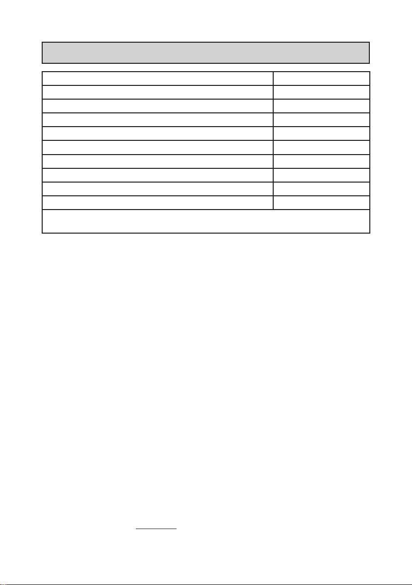
4.0 Tekniske Data
Ovn model Morsø 5660M
CO emission (ved 13% 02) (%) 0,05
OGC (tjære o.l.) emission (mg/m3) 30
Partikel emission, vægtet gennemsnit (g/kg) 3,9
Partikel emission, maks. i enkel prøvning (g/kg) 5,2
Virkningsgrad (%) 82
Nominel drifteekt (kW) 7,3
Røgtræk, minimum (Pa) 12
Forbrændingsluftforbrug (maks. indstilling) (m3/h) 20
Brændsel Træ
Alle måledata i henhold til prøvestandarder EN 13 240 samt NS 3058-3059.
Prøvninger er foretaget hos akkrediteret prøvningsinstitut.
Garanti
Produkt Registrering
MORSØ’S ÅRS PRODUKTGARANTI
Bag hver MORSØ brændeovn ligger mere end 160 års erfaring i udviklingsarbejdet samt en grundig
kvalitetskontrol foretaget af vore medarbejdere gennem hele produktionsprocessen.
Derfor giver MORSØ 10 ÅRS GARANTI med hensyn til materiale- og fabrikationsfejl.
Garantiperioden regnes fra salgsdato. For at sikre bedst mulig garantibehandling anbefales det at
udfylde garantikortet og registrere det med det samme .
Læs mere om ”Morsø’s 10 års produktgaranti og -registrering” og
REGISTER din nye Morsø ovn online:
http://denmark.morsoe.com/garantiregistrering
21
Page 22
Instructions for installation and use
5660M
22
EN 13240 · NS 3058-3059
MORSØ JERNSTØBERI A/S . DK-7900 NYKØBING MORS
E-Mail: [email protected] · Website: www.morsoe.com
Page 23

Enjoy your new Morsø stove!
Morsø, the biggest stove company in the Danish market, has been making wood-burning stoves of the
highest quality since 1853. Just follow the instructions
below, and we are certain that you will be able to use
and enjoy your new stove for many years.
Contents
1.0 Installing your Morsø stove Page no.
1.1 Unpacking the stove 24
1.2 Installing the stove 24
1.3 Chimney sweep 24
1.4 Location of the stove/distance requirements 26
1.5 The chimney 31
1.6 Connecting to a brick chimney 32
1.7 Connecting to a steel chimney 32
1.8 Draught 33
2.0 Firing/using the stove 34
2.1 Lighting instructions and fuelling intervals 35
3.0 Routine stove maintenance 38
3.1 External maintenance 38
3.2 Internal maintenance 38
3.3 Cleaning the stove 39
4.0 HETAS amendments 40
Additional accessories
Morsø also oers a comprehensive line of oor plates and accessory products that can facilitate the safe and ecient operation and maintenance of your Morsø stove.
Cast iron
Cast iron is a live material. There are no two ovens that are identical. This is partly due to the
tolerances of the casting process, partly because the ovens are a work of craftsmanship.
Minor unevennesses may also occur in the cast iron surface.
23
Page 24

1.0 Installing your Morsø stove
1.1 Unpacking the stove
We recommend that two persons perform this task since the stove is too heavy to handle
single-handedly. MORSØ 5660M weighs approximately 125 kg.
The stove is suited for intermittent use.
1.2 Installing the stove
National and local regulations regarding the installation of wood-burning stoves must be observed, as must local regulations regarding chimney connections and chimney installation. You
may want to ask your chimney sweep for advice. However, you, your technical adviser or workman are responsible for complying with the applicable national and local regulations.
1.3 Chimney sweep
As stated, it may be wise to consult your local chimney sweep before installing the stove. In
any event, the chimney sweep must be notied once the wood-burning stove has been installed. The chimney sweep will inspect the installation and schedule sweeping intervals with
you. If your chimney has not been used for some time, it should be inspected for cracks, bird
nests, etc., before it is used.
24
Page 25
Installation
SECTION
SCALE
1 : 12
The Morsø 5660M stove requires connection with a 45° pipe elbow (1) – either as a top-vent
elbow or another pipe elbow for rear vent.
Position of smoke-deector plates
On delivery, the smoke-deector plates (2) and (3), carried out in vermiculite, will have been
pre-tted.
Prior to lighting a re in the stove, the correct tting of the smoke-deector plates must be
veried (see sketch).
Rear vent
Top ven t
321
1 2 3
25
Page 26
1.4 Positioning the stove/distance requirements
Installation in the Morsø modular system
The insert stove, Morsø 5660M, is intended for installation in the Morsø insert modular
system.
The modular system comprises 3 module types:
• Module for Morsø 5660M insert
• Module for mounting under the insert
• Side modules
Adjacent materials must be non-ammable.
When put up on brickwork, a single layer of wallpaper will, in general, be considered to be
non-ammable material. A non-ammable cover plate should cover a oor area of minimum
300 mm in front of the furnace door and 150 mm to each side in front of the stoke hole.
Please note that the oor must be of sucient load capacity for the installation. If Morsø
5660M is intended for wall-hanging, it should likewise be veried whether the wall can take
the load of the installation.
Requirements as to distance will only be relevant in case the stove is to be installed adjacent
to ammable material.
The distance requirements are as follows:
Distance to furniture 1300 mm
Distance to ammable sidewall, at a right angle to the stove 400* mm
Height above ammable ooring, a minimum of 300** mm
26
400*
300**
300
150
Page 27
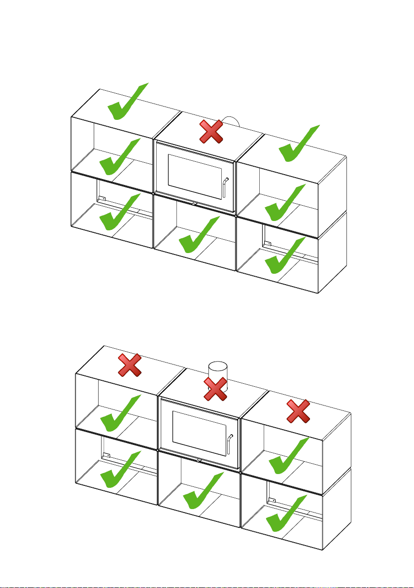
An example of Morsø 5660M modular system with rear vent.
Flammable materials will be allowed on surfaces with a check mark.
No ammable materials shall be allowed on surfaces marked with a cross
An example of Morsø 5660M modular system with top vent.
Flammable materials will be allowed on surfaces with a check mark.
No ammable materials shall be allowed on surfaces marked with a cross
27
Page 28
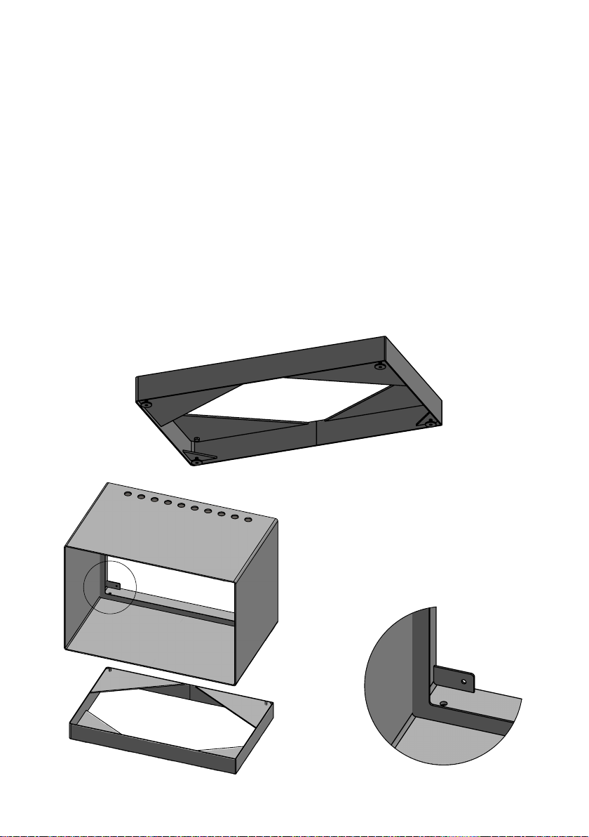
Installation of Morsø 5660M
B
B
B
4 dierent cabinets/modules are available for the modular system.
-1 module for combustion chamber with rear vent
-1 module for combustion chamber with top vent
-1 module for installation under the stove
-1 module for installation at the side of the stove
-1 base
-1 ue duct for rear vent
-1 ue duct for top vent
Positioning / mounting of Morsø 5660M
To avoid damages, 2 persons are recommended for the installation.
Where cabinets are to be wall-hanged, the supplied wall brackets are used. Please make
certain that the wall, as well as the bolts applied, can carry stove and modules. A module,
complete with stove, weighs 195 kg, whereas an empty module weighs 57 kg.
If only the stove module is mounted, you must allow for a minimum distance of 300 mm
between the module’s subsurface and the oor, if the ooring is of a ammable material.
If the stove is to be installed with a module under the stove, the two supplied bolts and the
four adjusting screws will be tted to the base which is then placed on the oor – in the
area that is intended as the nal position of the stove.
28
A
The base is levelled up, using the adjusting
screws. The module, with its holes placed at
the back of the module surface, is then placed
on the base in such a way that the two holes
at the bottom of the module will t the bolts
on the base (see sketches A and B). The base
and the module are screwed together, using
the supplied washers and nuts (see sketch C).
A
Page 29
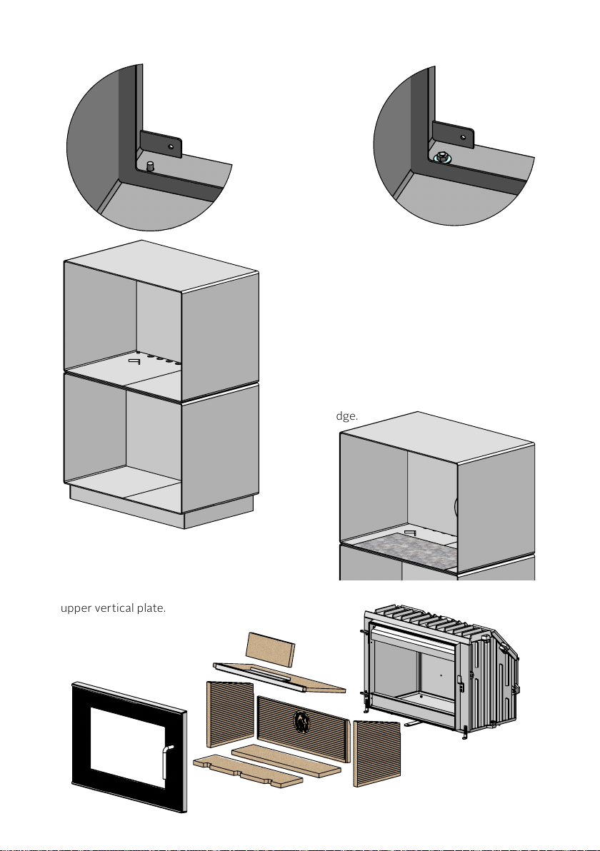
C
C
321
SECTION
C-C
SCALE
1 : 12
1 2 3
SECTION
B-B
SCALE
1 : 12
321
SECTION
SCALE
1 : 12
C-C
SCALE
1 : 12
1 2 3
B
Next, the supplied module, which has been prepared for installation of the combustion chamber, is
lifted into place.
Make sure to align the two Ø 10 holes at the back
of the module precisely above the two Ø 10 holes
of the module below. Insert the two supplied
M8x16 bolts into the holes – i.e. through both
modules.
Before installation of the oven, you mount the steel
rear plate – using the supplied magnets.
Position the supplied slide plate at the bottom of
the module and push until the edge binding meets
the module edge.
C
Dismantle the door from the oven and remove the vermiculite plates, beginning with the
upper vertical plate.
29
Page 30
SECTION
C-C
SCALE
1 : 12
1 2 3
300**
400*
321
SECTION
C-C
SCALE
1 : 12
1 2 3
B-B
1 : 12
321
SECTION
C-C
SCALE
1 : 12
SECTION
B-B
SCALE
1 : 12
321
SECTION
C-C
SCALE
1 : 12
1 2 3
321
SECTION
C-C
SCALE
1 : 12
1 2 3
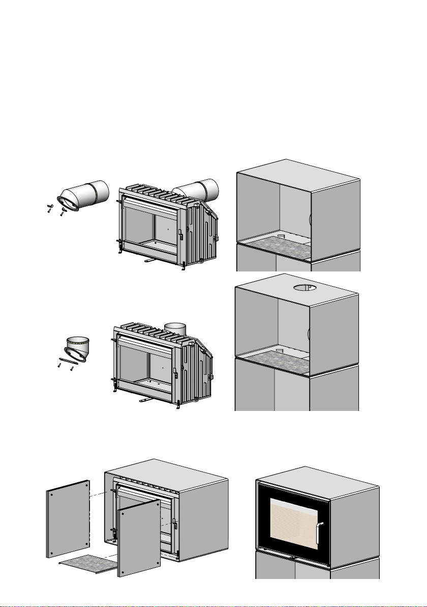
NOTE! WHEN FITTING OVENS WITH TOP-MOUNTED OUTPUT, THE FLUE DUCT CANNOT
BE FITTED BEFORE THE OVEN HAS BEEN INSERTED INTO THE MODULE.
As previously mentioned, on page 5, it will take 2 persons to install the oven, as the ue duct must
be lifted up through the top discharge point as the oven is inserted into the module, and not before
this has happened can the ue duct be secured to the oven by means of crews.
The ue duct is tted to the combustion chamber, and then the combustion chamber is lifted onto
the sliding plate upon which it can now be slid into position without leaving any marks on the module. The combustion chamber may now be levelled o by way of the tted adjusting screws. The
slide plate, no longer needed, is removed by lifting the oven a little at the front. The two ttings
at the bottom of the front frame are loosened until they slide down to meet the module bottom,
then retighten. This will prevent the oven from tilting when the door is opened.
Note: With outlet pipe towards the rear, the ball locking device is not to be used.
Rear vent
Top ven t
Now, place the lower radiation screen in its approximate position below the combustion
chamber, and the 2x3 sets of radiation plates (supplied in assembled states) are placed in
their approximate positions – one set each side (see sketch). Avoid pushing them all the
way up against the rear plate of the module. Next, the vermiculite plates are retted, the
upper vertical plate as the last. Finally, the door is remounted.
30
Page 31
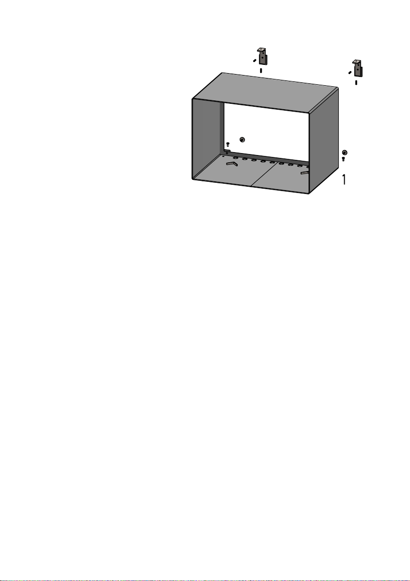
For wall-mounted installation, the modules can be levelled o by way of the
supplied adjusting screws and and levelling feet with the Allen key (see sketch).
When the installation of the combustion
chamber and the ue-duct arrangement
is completed, continue by mounting the
side modules, if relevant.
Please note that, for safety reasons, no
module is allowed above the combustion-chamber module.
Distance to furniture
We recommend that the stove be installed 1300 mm from furniture, but consideration should
also be given to whether furniture, etc., will dry out as a result of its proximity to the stove.
The distance to ammable material in front of the stove is 1300 mm.
A wood-burning stove gets hot when it is red. Caution must therefore be observed, particularly with regard to children touching the stove.
The stove is equipped with a detachable handle in stainless steel – a poor heat conductor.
When the handle is removed, the stove is more childproof at the same time.
1.5 The chimney
If local regulations permit, the stove may be connected to a chimney already serving another replace (such as an oil-burning stove or another wood-burning stove). Attention should
be paid to any requirements concerning the location of ue pipes if two or more replaces
are connected to the same chimney.
The wood-burning stove must never be connected to a chimney to which a gas-burning stove
is already connected. An ecient, modern stove places great demands on the chimney, so have
a chimney sweep check the condition of your chimney.
The aperture of the chimney must comply with national and local regulations. In general,
the aperture area should measure at least 175 cm2 (150 mm diameter) for wood-burning
stoves.
An overly large chimney aperture will mean that too much energy will be required to heat
the chimney suciently to achieve an acceptable draught. If you have a brick chimney with
a large aperture, we recommend that you install an insulating chimney liner of the proper
diameter. This will increase the draught, and improve the fuel economy.
There are no requirements with respect to specic chimney heights, but a chimney must be tall
enough to provide a good draught, and to ensure that the smoke does not cause any problems.
As a general rule, there will be a satisfactory draught if the chimney extends 4 metres above the
stove and at least 80 cm above the spine of the roof. If the chimney is located along the side of
the house, the top of the chimney should never be lower than the spine of the roof or the highest point on the roof. Please note that there are often national and local regulations regulating
the location of chimneys in houses with thatched roofs. Please see section 1.9 Draught.
31
Page 32
B-B
SCALE
1 : 12
321
SECTION
SCALE
The chimney and the ue pipe must be tted with cleaning doors, which must be at least
the same size as the chimney’s aperture area.
The chimney must be accessible for external inspection, and it must be possible to access
the cleaning doors and the chimney if it is to be cleaned from the top (e.g. steel chimneys).
1.6 Connecting to a brick chimney
A ue-duct liner is bricked into the brick chimney, and
the supplied str ap is taped onto the ue duct about 12
cm from the edge of the duct. The duct must not be
inserted into the actual chimney opening, as you can
go no further than to the interior side of the chimney
embrasure. Ordinarily it will not be necessary to seal
o pipe joints, if any.
If the ue pipe transitions from horizontal to vertical, it is a good idea to install it with a gentle bend so
as to avoid any loss of draught.
The ue pipe must be dimensioned in accordance
with national and local regulations. Morsø recommends, however, that ue pipes be made of 2 mm
sheet steel as this will extend the service life.
1.7 Connecting to a steel chimney
If your installation involves taking the chimney straight up and through the ceiling, you must comply with National, Local Building Regulations or ue manufacturers instructions concerning clearances to combustible materials such as walls, oor joists and ceilings. The joint between the stove
ue collar and the stovepipe must also be sealed using glass bre rope. It is important that the
insulated ue system is properly supported both at ceiling level and at roof level.
THE STOVE MUST NOT BEAR THE WEIGHT OF THE CHIMNEY SYSTEM (See chimney manufacturer’s instructions). Excessive weight on the stove will inhibit expansion and could lead
to damage of the stove top. Damage caused to the stove in this way would not be covered by
the manufacturers guarantee.
If a chimney re should occur as a result of incorrect operation of the stove or prolonged
use of wet fuel, close the vents completely and contact the re brigade.
Be aware of the following:
Cleaning procedure: Discuss this with chimney sweep or qualied installer prior
to or during the stove installation
If there is insucient draught in the chimney, it may be a good idea to install the
ue pipe straight up so as to minimise smoke migration in the actual combustion
chamber.
Avoid having any more than 2 bends in the ue system and limit the length of the
oset between bends.
Fresh air supply
A wood-burning stove requires air for combustion. As a result, ring a wood-burn
32
Page 33

ing stove will help create a healthy climate in your house. If the house is very tightly
sealed, and particularly if there is a cooker hood or ventilation system in the house, it
may be necessary to install an air grate in the room in which the wood-burning stove is
installed. Otherwise there may not be enough draught in the chimney, which may result in the stove not being able to burn properly, and smoke may come out of the stove
when the re door is opened.
If it is necessary to install air grates, they must be positioned so that they cannot
be obstructed.
1.8 Draught
If smoke comes out of the stove when the re door is opened, it will be due to the poor draught
in the chimney. This type of stove requires at least 12 PA of chimney draught to achieve satisfactory combustion and to prevent smoke from escaping. Smoke may, however, escape in any
event if the stove door is opened during vigorous ring, so this should be avoided.
The ue gas temperature at the rated output is 241°C relative to 20°C.
The ue gas mass ow is 6,8 gr./second.
If in doubt, you may want to get your chimney sweep to measure the draught in the chimney.
Draught
The draught in the chimney is the result of the dierence between the high temperature in the chimney and the cooler temperature outside. Other factors that determine
whether sucient negative pressure can be produced to create a draught include the
length and insulation of the chimney, and wind and weather conditions.
The draught will be reduced when:
- The temperature dierence is too low, e.g. in connection with a poorly insulated
chimney.
If the chimney is cold, it may help to light (burn up) a rolled-up newspaper in the
chimney’s cleaning door.
- The outside temperature is too high, e.g. during the summer.
- There is no wind.
- The chimney is not tall enough, with the result that it sits in the lee of the roof
surface or tall trees.
These conditions are also associated with the greatest risk of smoke coming
back down the chimney.
- Air is entering the chimney in undesired places, e.g. through cracked joints or
leaks in the cleaning door or the ue pipe.
- Unsealed, unused replaces are connected to the chimney.
- The ue pipe and chimney are clogged up with soot due to inadequate cleaning.
- The house is too tightly sealed (please see the section on Fresh air supply).
A good draught is achieved when:
- There is a big dierence between the temperature in the chimney and outside,
i.e. when the need for heating is greatest.
- The weather is clear and there is a good wind.
- The chimney is of the proper height, i.e. Minimum 4 metres above the stove, and
clear of the spine of the roof.
33
Page 34

2.0 Firing/using the stove
The heat emission of the stove is regulated with the regulation lever under the door.
The stove uses three types of combustion air. The secondary combustion air is supplied down
along the glass. This air is regulated with the lever under the door. The tertiary combustion air
is supplied to the combustion right over the re. This air supply may not be regulated. The pilot
combustion air provides for the activation of embers and keeps the combustion going even at
the lowest damper position. This air supply comes from two nozzles on the front frame below
the door. This air supply may not be regulated.
The nominal heat output of the stove is 7,3kW.
Your new Morsø stove is EN tested and recommended for burning wood.
NB!
Wood is a material that contains a great deal of gas (approx. 75%). The gases are released
when the wood is lit and heated. For this reason, it is important that these gases are ignited quickly after stoking. If the wood just lies smouldering, especially after re-stoking,
a lot of smoke is created which, in the worst case, may cause an explosive ignition of the
gases, resulting in damage to the stove.
In order to ignite the gases that are released from the wood, and to keep clear, lasting
ames during the combustion process, it is important to let in the required quantity of
oxygen (air supply) at all times. The setting of the air supply, the method of ignition and
the lighting intervals depend on the draught in the chimney, the wind and weather, the
amount of heat required, the fuel, etc. This means that it may take some time before
you get to know the correct functioning of the stove under any given circumstances.
Although you can re your Morsø stove with almost all kinds of wood, you should
not re with wet wood, or unseasoned wood. Wood ought to be stored under a roof
for at least 1 year, and preferably 2 years, with free access to wind. Wood should be
chopped as soon as possible after felling if it is to dry quickly. The wood can be used
once the moisture is less than 20%. During the test, all stoves are tested with wood
with a moisture content of (16 ± 4)%.
Never use driftwood as it usually has a high salt content, which damages both
the stove and the chimney. Impregnated and painted wood and chipboard emit
poisonous smoke and fumes so they should not be used as fuel either
34
Please note that liquid fuel may not be used in the stove.
Pieces of wood with a diameter exceeding 10 cm should always be chopped. The pieces
of wood should be short enough to be able to lie at over the layers of embers, with air
at both ends. The maximum leng th of fuel in the stove is 30 cm. The maximum quantity
of fuel is approx. 2 kg/hour (max. 2 pieces of wood each time you re-stoke).
The rst few times you light the stove, the re should be moderate so that the heatresistant paint can harden before ring more vigorously. During the hardening phase,
the paint may develop obnoxious smoke and smell the rst time it is lit, which is very
normal. Make sure that the room is well ventilated during this period.
When heating up or cooling down, the material is exposed to major temperature
dierences that may cause the stove to give o creaking sounds.
Page 35
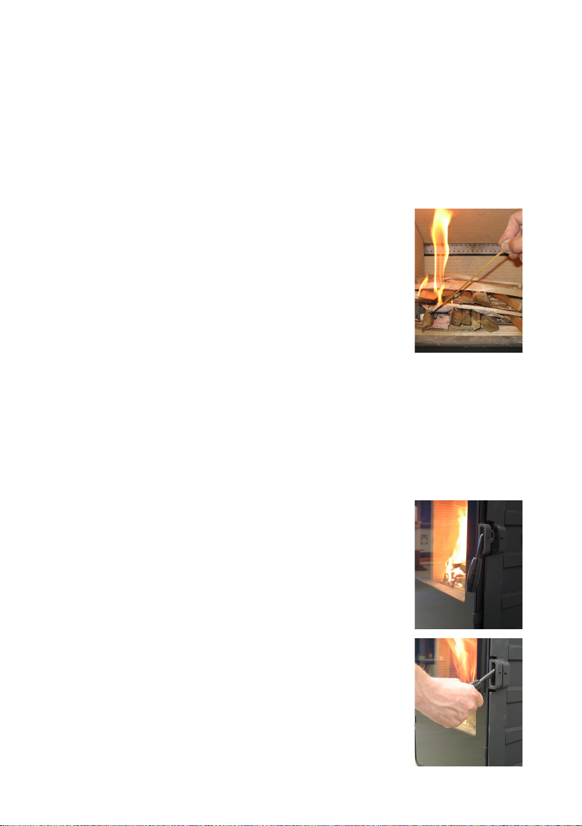
2.1 Lighting instructions and fuelling intervals
A lot of air is needed when lighting the stove. If you are starting with a cold stove, the door
should be left ajar for the rst few minutes. In order to build up an insulating layer of ash in
the bottom of the stove, you should burn 3 kg of dry kindling when you light the stove the
rst time.
Always keep approx. 1 cm ash in the bottom of the combustion chamber.
1. We recommend using the “top-down” method to light
your wood-burning stove. It is the most environmentallyfriendly method of lighting. Use 2-3 relighters and approx. 3-4 kg of dry kindling sticks to quickly create a glowing layer of wood. Place the relighters directly under the
top layer of kindling sticks.This minimizes soot formation
on the glass. Soot formation on the glass is often caused
by too vigorous burning in contact with cold surfaces. If
you avoid the formation of soot when lighting the re and
build up a layer of hot embers, you will have minimal soot
formation when getting the re burning again later.
2. Open up completely for the secondary air supply by means
of the regulation lever.
3. Af ter the paper/solid alcohol tablet s have caught re, leave
the re door ajar about 2 cm so that the chimney draws well.
4. When you can see that the chimney is hot enough to draw
(after 5-10 minutes), close the door. If all the necessary conditions are met, a thick layer of embers will have been formed in
the combustion chamber after another 15-20 minutes.
35
Page 36
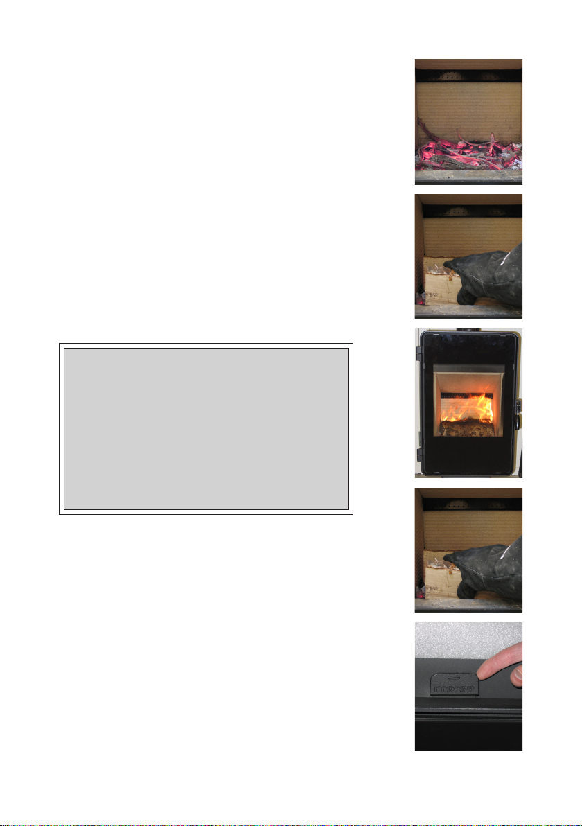
5. Re-stoking should normally be carried out while embers
still remain. Distribute the embers in the bottom, ensuring
that most of them are at the front of the stove.
6. Place 2-3 logs of rewood, each weighing approximately
0.7-1 kg and 30-50 cm long, over the embers in one layer
separated by approximately 1 cm. The best combustion is
obtained if the longitudinal dimension of the logs is parallel
with the rear wall of the stove.
7. When the secondary air supply is opened to maximum
and the door is closed, the new quantity of wood will ignite in a few minutes.
Important!
It is important that the fresh quantity of wood starts
to burn qu ickly. To ensure th e fuel lights qu ickly, open
the combustion air to max. or leave the door ajar to
allow in the amount of air needed to light the wood.
If, however, the wood only smoulde rs, there will be a
strong build-up of smoke, which at worst can cause
an explosive ignition of the ue gases with the risk
of material damage and personal injury.
8. Subsequently, the secondary air supply is adjusted to the
desired level, and the optimum combustion will continue until only embers are left.
Make sure that there is always enough air (oxygen) to maintain cle ar, lasti ng ames when , and after, reduci ng the amount
of combustion air.
Under the nominal test, the rell interval was 60-70 minutes.
9. A new portion of wood can be added by repeating steps
5 & 6.
36
Page 37

The stove door should normally be opened gently the rst 2-3 cm, then you should wait until
the pressure has equalised before opening the door all the way. This technique will prevent
smoke from getting out, particularly when there is a poor draugt.
The stove door should never be opened when the stove is being red vigorously.
Once the wood has burned out, it becomes glowing charcoall. If a good layer of embers has
already formed on top of a sucient layer of ash, the stove can keep warm for a very long
time, not least due to the favourable qualities of the cast iron.
We would strongly recommend that you do not leave your stove alit at night. It
harms the environment and constitutes very poor use of the wood as the gases
in the wood do not ignite at the low temperature, but settle as soot (unburned
gases) in the chimney and stove. Extreme conditions, such as poor draught in the
chimney, large quantities of wood or wet wood, may in the worst-case scenario
cause an explosive ignition.
When ring in the summer period, when there is minimal need for heat, the combustion
will be poor. The stove provides too much heat so the combustion should be reduced.
But always remember to make sure that there are lasting ames until the wood becomes charcoal. If you want a weaker re, stoke up using less wood.
If you re the stove using wet wood, a lot of the fuel’s thermal energy will be spent
forcing the water out of the wood, without releasing any heat to the stove. This
incomplete combustion results in a layer of soot being left in the stove, pipe and
chimney.
Comparison between ring with wood and oil:
Type of wood (moisture content 20%) No. of cubic metres per 1000 litre oil
Oak
Beech
Ash
Sycamore
Birch
Elm
Common spruce
Silver r
7.0
7.0
7.2
7.5
8.0
8.9
10.4
10.9
37
Page 38
3.0 Routine stove maintenance
3.1 External maintenance
The cast surface of the stove is painted with heat-resistant Senotherm paint. It is best maintained by simply vacuuming it with a soft brush attachment or wiping it down with a dry,
dust-free cloth.
If the stove is used too vigorously, the painted surface may assume a greyish tinge over time,
but the stove can easily be freshened up with Morsø spray paint, which is available from your
local retailer.
Morsø stoves are painted using a Morsø Original Black (previously called Morsø dark grey)
or Morsø grey. The paint can be bought in a spray or a can.
3.2 Internal maintenance
Glass window
If the stove is used correctly, very little or no soot will be deposited on the ceramic glass window.
If soot does form on the glass as the stove is being lit, it will burn away once normal combustion
begins in the stove. If the glass window becomes thoroughly covered in soot due to incorrect operation, the soot can be easily removed using a cleaning agent such as Morsø Glass Cleaner. The
glass must be cold when you clean it. Avoid stoking the stove with pieces of wood that are so long
that they press against the glass window when the door is closed.
Reasons for sooty glass window:
- The fuel is too wet.
- The pieces of fuel are to big/uncut wood.
- The combustion temperature is too low.
Ceramic glass replacement
Ceramic glass cannot be recycled because it has a higher melting point that ordinary glass.
If ceramic glass is mixed with ordinary glass, the raw material is spoiled, and the reclaiming
process may be halted. Take care that the ovenproof glass does not end up among ordinary
recycled waste. That will be a great benet to the environment.
Note: Should be handed in to a recycling station as ceramic glass.
Interior cast iron parts and other wear and tear parts
Vermiculite stones and other parts that are in direct contact with re and burning fuel are wear
and tear parts. As such, they are particularly exposed to being burnt through. Used correctly,
these parts will last many years; but ring too heavily will of course accelerate burning through.
The parts mentioned may easily be changed.
If the bae plate is damaged and not replaced in time, the top plate will be exposed to such
high temperatures that it may be damaged.
Note that unauthorized changes of the construction may not be made, and parts may
only be replaced with original Morsø parts.
38
Page 39

Reasons for overly rapid wear of internal parts
- Stove red too vigorously.
- Use of very dry wood (wood from old furniture).
- Too much soot on top of the baes (please see the section on Cleaning).
- Too much ash in the ash pan (please see the section on Ash).
Gaskets
With time, the gaskets in the door will wear, and, in order to avoid wild combustion, they
must be replaced as required. Use an original Morsø gasket kit that is supplied with precise
instructions for use.
Note: Normal wearing parts are not covered by Morsø’s extended warranty.
A selection of maintenance products (spare parts, glass cleaner, paint, gasket kit, etc.) is available from your Morsø dealer.
3.3 Cleaning the stove
Ashes and soot will settle, especially over the bae plate, because of the draft in the chimney and
after a s weeping. The ashes have an insulating eect that may accelerate the burning through of the
bae plate because it cannot give o the heat. The bae plate may be taken out of the stove during
normal cleaning. Today, the chimney sweep, in addition to sweeping the chimney and cleaning the
ue pipes, must take care of removing soot from the stove.
The chimney sweep will establish the annual number of sweeps and cleanings after having
consulted you.
Ash
As noted above, there should be a layer of approximately 1 cm insulating ash in the bottom
of the combustion chamber in order to achieve a high combustion temperature. If the layer
of ash is too thick, it can be brushed down with an ash shovel, dustpan or similar tool.
In most cases, the ash will need to be taken away by the waste disposal company. Because
embers may be concealed in the ash pan for several days, it may be necessary to store the
ash in a container made of non-ammable material before pouring it into a rubbish bag.
Ash from a wood-burning stove will not be of any benet to your garden as fertiliser. If you
have burned colour brochures, or painted or treated wood, etc., in the stove, the resulting
ash must not be poured onto soil as it may contain heavy metals.
39
Page 40

4.0 HETAS amendments
Health and safety precautions
Special care must be taken when installing the stove such that the requirements of the Health
and Safety at Work Act are met.
Handling
Adequate facilities must be available for loading, unloading and site handling.
Fire Cement
Some types of re cement are caustic and should not be allowed to come into contact with
the skin. In case of contact wash immediately with plenty of water.
Asbestos
This stove contains no asbestos. If there is a possibility of disturbing any asbestos in the course
of installation then please seek specialist guidance and use appropriate protective equipment.
Metal Parts
When installing or servicing this stove care should be taken to avoid the possibility of personal injury.
Note of references to the current UK regulations
In all cases the installation must comply with current Building Regulations, Local Authority
Byelaws and other specications or regulations as they aect the installation of the stove.
It should be noted that the Building Regulations requirements may be met by adopting the
relevant recommendations given in British Standards BS 8303, BS EN 15287-1:2007 as an
alternative means to achieve an equivalent level of performance to that obtained following
the guidance given in Approved Document J.
Please note that it is a legal requirement under England and Wales Building Regulations that
the installation of the stove is either carried out under Local Authority Building Control approval or is installed by a Competent Person registered with a Government approved Competent Persons Scheme. HETAS Ltd operate such a Scheme and a listing of their Registered
Competent Persons can be found on their website at www.hetas.co.uk.
This stove must not be installed into a chimney that serves any other heating appliance.
More detailed advice about existing chimney usage
NOTE: A chimney height of not less than 4.5 metres measured vertically from the outlet of
the stove to the top of the chimney should be satisfactory. Alternatively the calculation procedure given in EN 13384-1 may be used as the basis for deciding whether a particular chimney
design will provide sucient draught.
The outlet from the chimney should be above the roof of the building in accordance with
the provisions of Building Regulations Approved Document J.
If installation is into an existing chimney then it must be sound and have no cracks or other
faults which might allow fumes into the house. Older properties, especially, may have chimney faults or the cross section may be too large i.e. more than 230 mm x 230 mm. Remedial
action should be taken, if required, seeking expert advice, if necessary. If it is found neces
sary to line the chimney then a ue liner suitable for solid fuel must be used in accordance
with Building Regulations Approved Document J.
40
Page 41

Any existing chimney must be clear of obstruction and have been swept clean immediately
before installation of the stove. If the stove is tted in place of an open re then the chimney
should be swept one month after installation to clear any soot falls which may have occurred
due to the dierence in combustion between the stove and the open re.
If there is no existing chimney then any new system must be to the designation described
above and in accordance with Building Regulations Approved Document J.
A single wall metal uepipe is suitable for connecting the stove to the chimney but is not
suitable for use as the complete chimney. The chimney and connecting uepipe must have
a minimum diameter of 150 mm and its dimension should be not less than the size of the
outlet socket of the stove.
Any bend in the chimney or connecting uepipe should not exceed 45°. 90° bends should
not be used.
Combustible material should not be located where the heat dissipating through the walls of replaces or ues could ignite it. Therefore when installing the stove in the presence of combustible
materials due account must be taken of the guidance on the separation of combustible material
given in Building Regulations Approved Document J and also in these stove instructions.
If it is found that there is excessive draught in the chimney then a draught stabiliser should be
tted. Fitting of a draught stabiliser will aect the requirement for the permanent air supply
into the room in which the stove is tted in accordance with Approved Document J (see also
combustion air supply).
Commissioning and handover
Ensure all parts are tted in accordance with the instructions.
On completion of the installation allow a suitable period of time for any re cement and mortar to dry out, before lighting the stove. Once the stove is under re check all seals for soundness and check that the ue is functioning correctly and that all products of combustion are
vented safely to atmosphere via the chimney terminal.
On completion of the installation and commissioning ensure that the operating instructions
for the stove are left with the customer. Ensure to advise the customer on the correct use
of the appliance and warn them to use only the recommended fuel for the stove.
Advise the user what to do should smoke or fumes be emitted from the stove. The customer
should be warned to use a reguard to BS 8423:2002 (Replaces BS 6539) in the presence of
children, aged and/or inrm persons.
Warning note on fume emission
Properly installed, operated and maintained this appliance will not emit fumes into the dwelling.
Occasional fumes from de-ashing and re-fuelling may occur. However, persistent fume emission is potentially dangerous and must not be tolerated. If fume emission does persist, the following immediate actions should be taken:
A. Open doors and windows to ventilate room.
B. Let the re out or eject and safely dispose of fuel from the appliance.
C. Check for ue or chimney blockage, and clean if required.
Do not attempt to relight the re until the cause of the fume emission has been identied
and corrected. If necessary seek expert advice.
41
Page 42

Extractor fan
There must not be an extractor fan tted in the same room as the stove as this can cause
the stove to emit smoke and fumes into the room.
Permanent air vent
The stove requires a permanent and adequate air supply in order for it to operate safely
and eciently.
In accordance with current Building Regulations the installer may have tted a permanent
air supply vent into the room in which the stove is installed to provide combustion air. This
air vent should not under any circumstances be shut o or sealed.
Chimney cleaning
The chimney should be swept at least twice a year. It is important that the ue connection
and chimney are swept prior to lighting up after a prolonged shutdown period.
If the stove is tted in place of an open re then the chimney will require sweeping after a
month of continuous operation. This is a precaution to ensure that any “softer ” deposits left
from the open re usage have not been loosened by the higher ue temperatures generated by the closed stove.
Periods of Prolonged Non-Use
If the stove is to be left unused for a prolonged period of time then it should be given a thorough
clean to remove ash and unburned fuel residues. To enable a good ow of air through the appliance to reduce condensation and subsequent damage, leave the air controls fully open.
Use of reguard
When using the stove in situations where children, aged and/or inrm persons are present
a reguard must be used to prevent accidental contact with the stove. The reguard should
be manufactured in accordance with BS 8423:2002 (Replaces BS 6539).
Use of operating tools
Always use the operating tools provided when handling parts likely to be hot when the
stove is in use.
Aerosol sprays
Do not use an aerosol spray on or near the stove when it is alight.
42
Page 43

Spare parts for the 5660/5660M
Description Product no.
Stone, rear 79560200
Stone, side 79560300
Stone, bottom front 79561600
Stone, bottom rear 79561700
Bae plate, top 79560700
Bae plate, bottom 79561100
Guarantee
Product Registration
MORSØ 10 YEAR GUARANTEE CERTIFICATE
Behin d every Mors ø stove is more tha n years of dedicated stove design and manufacturing experience. Quality control has always been at the heart of the production process and detailed measures
have been put into place at all key stages of the build. Accordingly, provided that the stove has been
supplied by an authorised Morsø dealer, Morsø will oer a 10-Year Manufacturers Guarantee against
manufacturing defect to any of the main exterior body parts of its stoves.
Read more about ”Morsø 10 years guarantee/product registration card” and
REGISTER your new Morsø stove online:
http://international.morsoe.com/warranty-registration
43
Page 44

VIGTIGT!
Sådan fyrer du sikkert for miljøet
og dig selv!
IMPORTANT!
How to heat safely for the environment and yourself!
• Brug kun tørt træ
Brug kun tørt (maks. 20% fugt) og ube-
handlet træ. Brændet skal være kløvet
og 8 - 12 cm tykt.
• Tænd op
Tænd op med tørt pindebrænde (brug
1 - 2 kg). Stil lågen på klem og bliv i nærheden af ovnen i optændingsfasen.
• Godt glødelag
Sørg for at have et godt glødelag inden
ny påfyldning. Træet skal antænde indenfor 2 min. Hvis træet ikke tænder,
kan det i værste fald forårsage en eksplosionsagtig antændelse af røggasserne med risiko for såvel materielle skader
som personskader.
• Indfyring
Ved ny indfyring: brug 2 - 3 stk. brænde
- maks. 2 - 2,5 kg.
• Sørg for rigelig luft
Dvs. klare og gule ammer.
• Fyr aldrig over om natten
• Use only dry wood
Use only dry (max. 20% moisture content)
and untreated wood. The fuel must be split
and 8 - 12 cm thick.
• Light
Light with dry kindling (use 1 - 2 kg). Leave
the door ajar and stay close to the stove
during the lighting phase.
• Good layer of embers
Be certain to have a good layer of em-
bers before relling. The wood should
light within 2 minutes. If the logs do
not ignite it may, in an extreme case,
cause the flue gases to ignite which
may pose a risk to material damage or
personal injury.
• Refuelling
When refuelling use 2 - 3 pieces of wood
- no more than 2 - 2.5 kg.
• Ensure adequate air
I.e. clear and yellow ames.
• Never burn overnight
44
Morsø Jernstøberi A/S - 11.03.2019 - 72562700
MORSØ JERNSTØBERI A/S . DK-7900 NYKØBING MORS
E-Mail: [email protected] · Website: www.morsoe.com
 Loading...