

Page 1
1
Installation and Operating Instructions
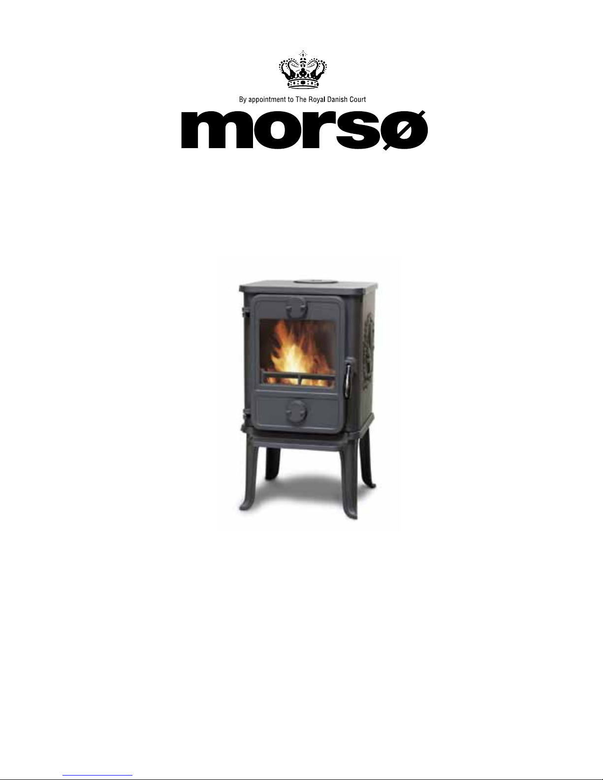
1410 Coal Heater
For use in North America
Read this entire manual before you install and use your new room heater. If this room
heater is not properly installed, a house fire may result. To reduce the risk of fire, follow
the installation instructions. Failure to follow instructions may result in property damage,
bodily injury, or even death.
Contact local building officials about restrictions and installation inspection-equirements
in your area.
Save these instructions
Distributed by: MORSO US LLC
1011 Highway 52 West - Portland TN - 37148 - USA
Page 2

2
We congratulate you on your choice of a Morsø stove. Morsø has
been producing some of the world’s best stoves since 1853. If you
follow these installation- and operating instructions carefully, we can
assure you many years of warmth and pleasure.
Optional Accessories
A wide range of accessories (such as handling gloves, fireside tools, glass cleaner and heatproof
paint) are available for use with your Morsø stove. They help with day-to-day running and
maintenance. Contact your Morsø dealer for more information.
The Morsø 1410 squirrel Coal Heater is listed by OMNI-Test Laboratories, Inc. The test standards
are ULC-S627 for the United States.
This heater is only for burning coal. Use of any other solid fuel exept for coal ignition
purposes is a violation of Federal law.
Cast iron
Cast iron is a live material. There are no two ovens that are identical. This is partly due to the
tolerances of the casting process, partly because the ovens are a work of craftsmanship.
Page 3

3
CONTENTS :
1.0 Installation of your Morsø stove
1.1 Checking loose parts in the stove 4
1.2 The chimney / flue system 5
1.3 Flue Connection 6
1.4 Connection to existing chimney 6
1.5 Positioning the stove 8
2.0 Operation
2.1 Before you start firing 10
2.2 Lighting and loading intervals 10
3.0 Maintenance
3.1 Exterior maintenance 12
3.2 Internal maintenance 12
3.3 Cleaning the Stove and the Flue 14
3.4 Leaving the stove for extended periods 16
3.5 Parts diagram 17
3.6 Parts list 18
Page 4

4
Installation requirements vary in different districts, and the local building officials have the final
authorization to approve your installation. You should discuss the installation with them before
beginning. Please ask your dealer for further information.
Do not connect to any air distribution duct or system
.
Important: If the installation instructions are not followed carefully, it may cause
dangerous situations like chimney and house fires. Follow the instructions
carefully and do not deviate from them as it may cause injuries to people or
property.
1.1 Checking loose parts in the stove
After unpacking, check that the center grate (in the center of the fire bed) and the fire bricks and
the baffle are firmly in position and have not shifted in transit. Check also that the air control
works freely.
Standard Accessories
Poker, ceramic flue connection gasket and riddling tool are standard accessories, and can
usually be found in the ashpan or firebox area.
1.0 Installation of your Morsø stove
Installation of coal heaters must be safe and legal.
If your Morsø stove is not installed correctly, it may cause a house fire. To reduce
the risk of fire, the installation instructions must be followed carefully. Contact the
local building officials about restrictions and installation inspection in your area.
Before you start installing your stove, make sure that:
- The stove and chimney connection are placed far enough from combustible materials to
meet all clearance requirements.
- The floor protection must be adequate and must be made correctly according to ´the re-
quirements.
All neccessary approvals are needed from the local building officials.
The data plate, which is located on the back of the stove, provides information regarding safety
testing information, name of certified testing laboratory, and installation requirements.
Page 5
5
1.2 The chimney / flue system
Note that the flue system must be independently secured and must not rely on the stove for
support.
The stove must not be connected to a chimney flue serving any other appliance.
(Several flues may run up a single chimney stack; use one flueway per appliance).
Use a residential type masonry or listed type HT factory-built chimney.
High Temperature (H.T.) Chimney Standard UL-103-1985 (2100º F.) for the USA, and
High Temperature (650ºC) Standard ULC S-629 for Canada.
The internal dimensions of the chimney connector and chimney must not be less than 6 inches
diameter (or equivalent cross section), and should not be significantly larger than this. Too
large a section will tend to allow the flue gases to cool excessively, causing sluggishness or
unpredictability in the stove’s performance.
We recommend the length of the chimney system should be at least 16 feet (not required)
above the stove in normal domestic situations, measured from the flue collar to the top of the
chimney.
Local conditions like for example - roof constructions, large trees nearby and high altitude,
may influence the chimney draft and height. Therefore, contact the local professional chimney
sweep or your Morsø dealer.
If using a barametric draft regulator, be advised that the maximum allowable chimney draft is
0,06 in-w.c. for this unit.
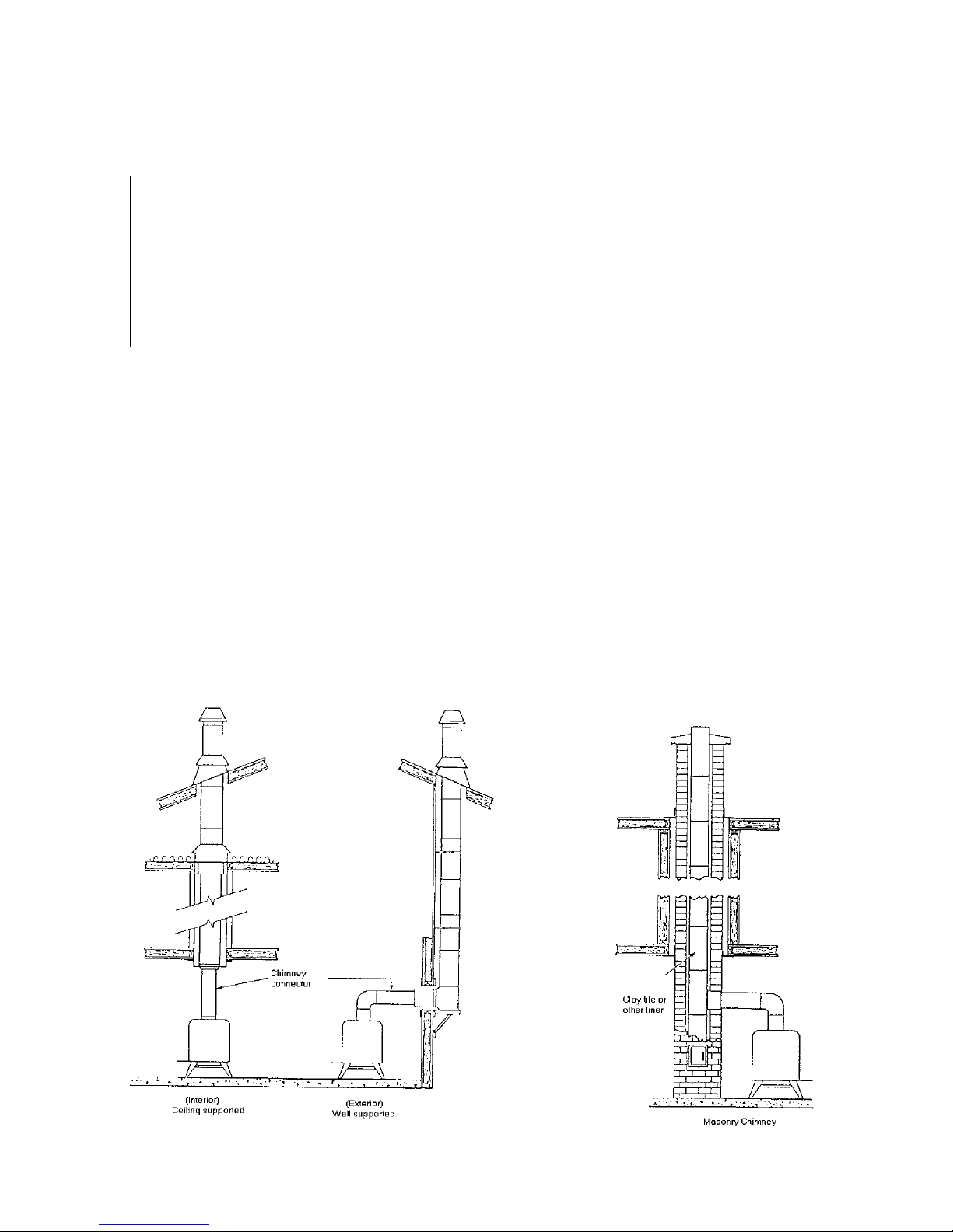
Typical Factory-Built or Masonry Chimney Installations
Page 6

6
Double-wall connectors must be tested and listed for use with solid-fuel burning appliances.
Single-wall connectors should be made of 24 gauge or heavier gauge steel. Do not use
galvanized connector; it cannot withstand the high-temperatures that smoke and exhaust gases
can reach, and may release toxic furnes under high heat. The connector must be 6 inches
(150mm) in diameter.
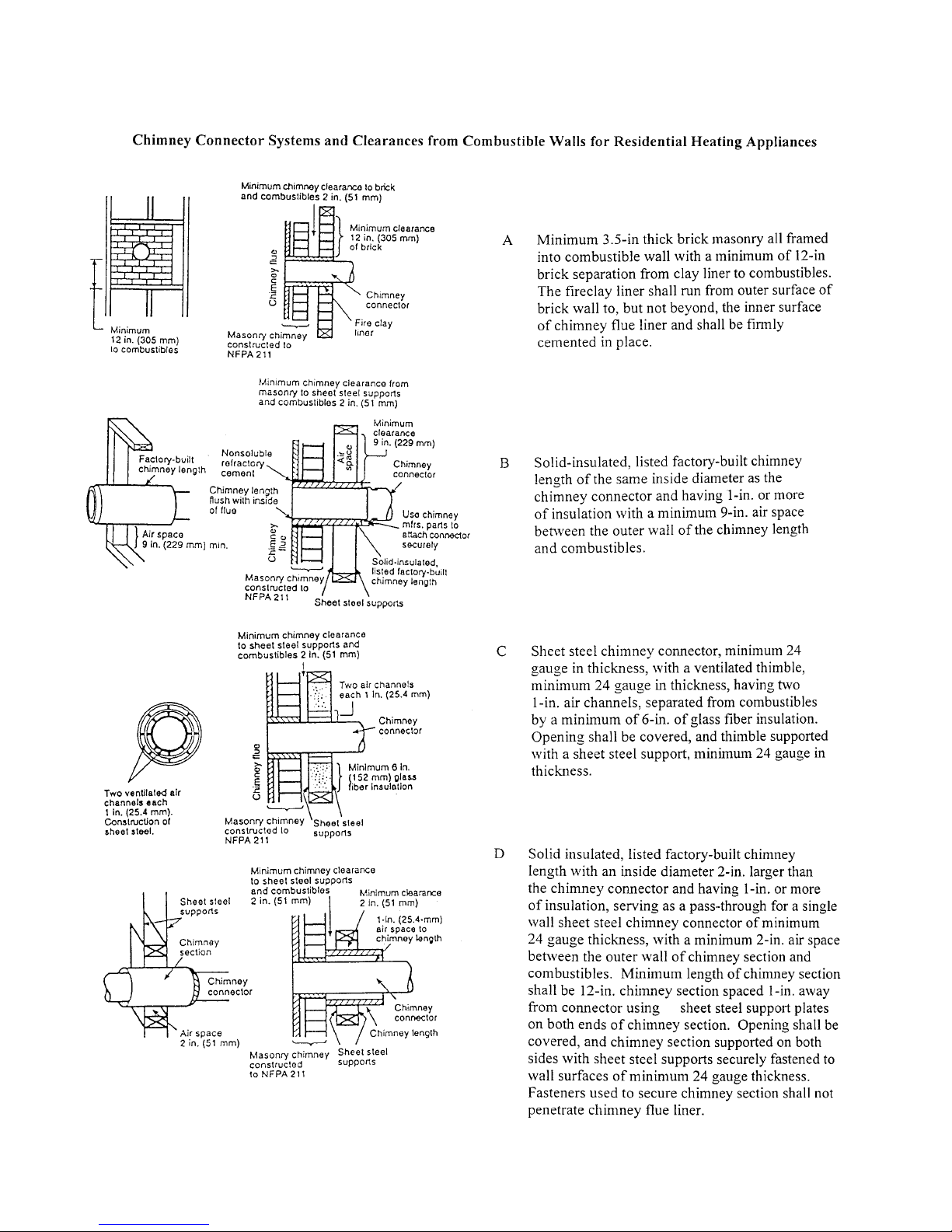
If possible, do not pass the chimney connector through a combustible wall or ceiling.
If passage through a combustible wall is unavoidable, refer to the sections on Wall
Pass- Throughs. Do not pass the connector through an attic, a closet or similar
concealed space when installing the chimney connectors.
It is important to keep the flue gases moving smoothly in the right direction. Do not vent into a
large void at this location; rather form one continuous section all the way up. Use mild bends
(e.g. 45º vs. 90º) rather than sharp angles where a change of direction is required. All parts of
the venting must be accessible for cleaning purposes.
In horizontal runs of chimney, maintain a distance of 18 inches from the ceiling. Keep it as
short and direct as possible, with no more than two 90 degree turns. Slope horizontal runs of
connector upward 1/4 per foot (20 mm per metre) going from the stove toward the chimney.
The recommended maximum length of a horizontal run is 3 feet (1 metre), and the total length
should be no longer than 8 feet (2.5 metres).
Information on assembling and installing connectors is provided by the manufacturer’s
instructions exactly as you assemble the connector and attach it to the stove and chimney.
Be sure the installed stove and chimney connector are correct distances from near by
combustible materials. See the clearance paragraph page 8.
1.3 Flue Connection
The stove is supplied from the factory with a flue collar fitted to the top plate and a round blanking
plate blocking off the rear flue exit (behind the rear shield plate).
The flue collar is 6 inches in dia.
Use a 24 MSG black or blue chimney connector or listed double wall chimney connector. Refer
to local codes and the chimney manufacturer’s instructions for precautions required for passing
a chimney through a combustible wall or ceiling. Remember to secure the chimney connector
with a minimum of 2 screws to the product and to each adjoining section.
The collar can be fitted to the rear outlet. Simply knock out the round panel on the rear heat
shield plate to reveal the cast iron plate. Untwist the blanking plate and the flue collar and swap
their positions. Re-secure by pushing down and tighten the enclosed screws.
Position the stove and connect to the flue system.
Wear gloves and protective eyewear when drilling, cutting or joining sections of chimney
connector
1.4 Connection to the existing chimney
A Chimney connector is the double-wall or single-wall pipe that connects the stove to the
chimney. The chimney itself is the masonry or prefabricated structure that encloses the flue.
Chimney connectors are used only to connect the stove to the chimney.
Page 7
7
Page 8
8
1.5 Positioning the stove
Distance to walls
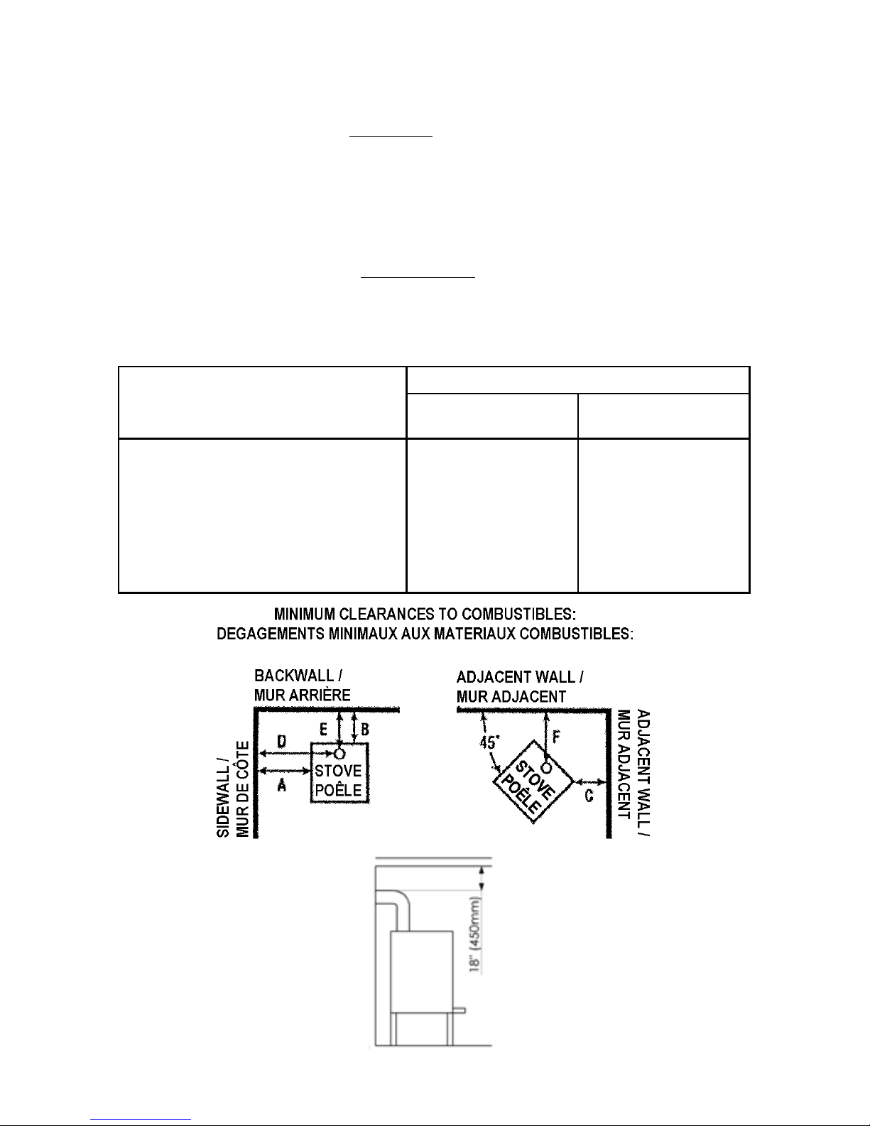
When the stove is positioned near combustible materials, observe all current local and national
building regulations with regards to clearances. Whatever regulations apply to your area, do
not in any case install the stove within 8 inches of combustible materials around the sides or 16
inches above the top of the stove. These distances may need to be increased if the materials
are sensitive to heat. Note also that wall paper and other decorative materials may become
detached with the effects of heat and care should be taken to ensure that they do not fall towards
the stove in such an event.
When the stove is positioned near non-combustible materials, a gap of 4 inches or more is
recommended for cleaning purposes and to ensure that heat circulates around the stove and
out into the room.
Clearance chart:
CLEARANCE REQUIREMENTS STANDARD RESIDENTIAL INSTALLATION
SINGLEWALL
CONNECTOR
DOUBLEWALL
CONNECTOR
A.
B.
C.
D.
E.
F.
G.
H.
19’’ (483mm)
10’’ (254mm)
13’’ (330mm)
24’’ (610mm)
12’’ (305mm)
18.5’’ (470mm)
56.5” (1435mm)
84” (2134mm)
19’’ (483mm)
6’’ (153mm)
13’’ (330mm)
23.5’’ (598mm)
7.5’’ (190mm)
18’’ (457mm)
56.5” (1435mm)
84” (2134mm)
SIDEWALL TO UNIT
BACKWALL TO UNIT
CORNERWALL TO UNIT
SIDEWALL TO CONNECTOR
BACKWALL TO CONNECTOR
CORNERWALL TO CONNECTOR
UNIT TO CEILING
FLOOR TO CEILING
Page 9
9
Distance to furniture
The recommended minimum distance from stove to furniture is 30 inches. Note that some
furniture is more easily affected by heat and may need to be moved to a greater distance. This
is your responsibility.
In addition other combustible materials, away from the stove. In general, a distance of 30 inches
must be maintained between the stove and moveable combustible item such as drying clothes,
newspapers, firewood etc.
Note:
Acid Protection
If acid-washing the masonry around the stove, protect the stove surface with an acid-proof
cover
Fresh Air Inlet
Unless there is deemed to be sufficient ambient leakage of air into the room via doorways,
windows and the like, a dedicated fresh air inlet will be needed. This inlet should have 2
square inches (1250 square mm) of free air space. This is particularly important where the
room is well sealed, or where an extractor hood or ventilation system disturbs the natural air
pressure. Such an inlet should not be on a wall that is usually subject to negative pressure
from normal wind pattern. Avoid placing the inlet directly across the room from the stove,
thus causing a cold air draft.
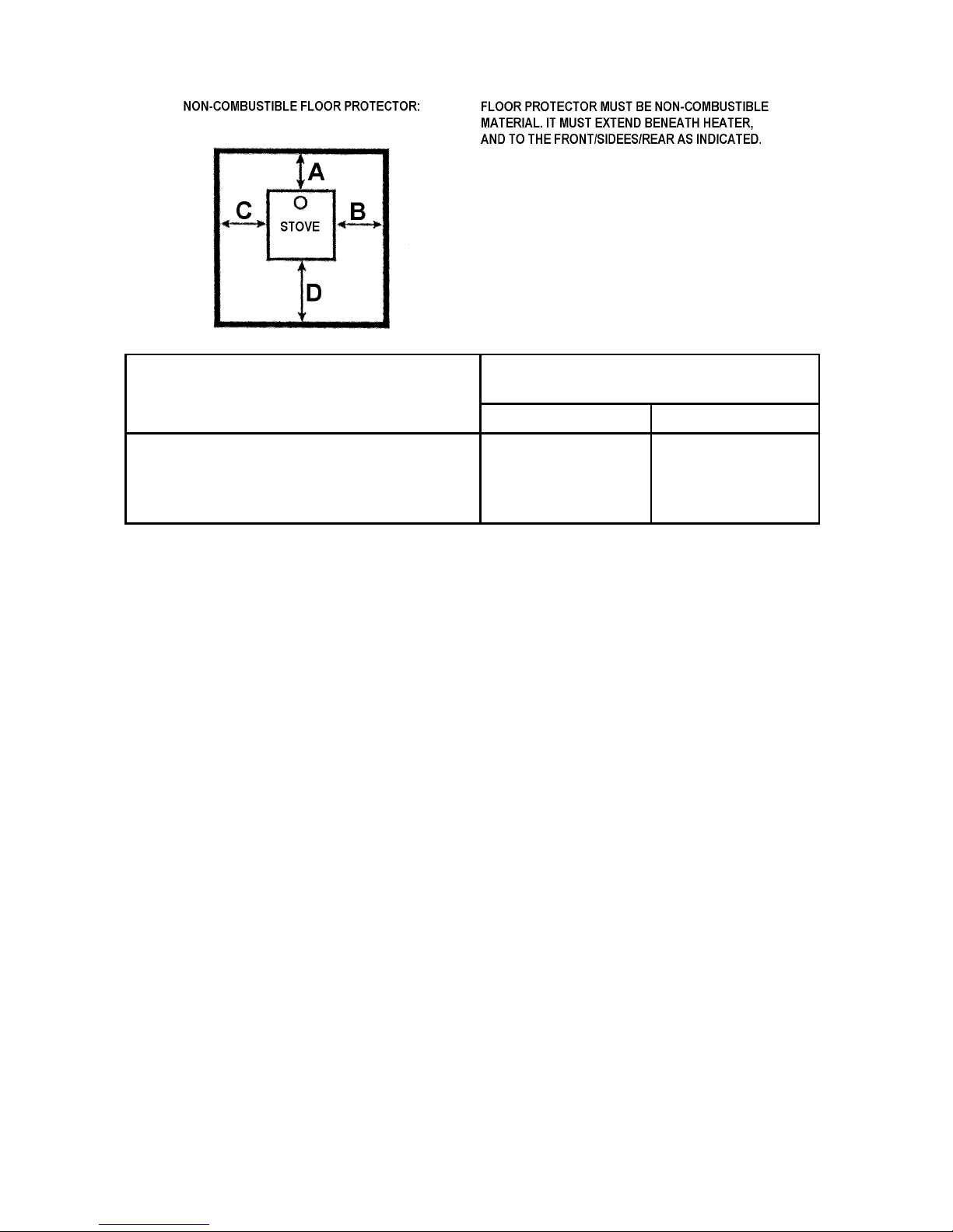
FLOOR PROTECTION REQUIREMENTS NON-COMBUSTIBLE MATERIALS
BENEATH STOVE
USA CANADA
A.
B.
C.
D.
8’’
8’’
16’’
200 mm.
200 mm.
200 mm.
450 mm.
EXTENDING DISTANCE, BACK
EXTENDING DISTANCE, RIGHT SIDE
EXTENDING DISTANCE, LEFT SIDE
EXTENDING DISTANCE, FRONT
Page 10

10
2.0 Operation
2.1 Before you start firing
For Use with Coal Only. Do Not Overfire, If Heater or Chimney Connector
Glows You Are Overfiring. Inspect and Clean Chimney Frequently. Under Certain
Conditions of use creosote buildup may occur rapidly. Because of risk of smoke and
flame spillage, operate only with door fully closed.
Caution:
Hot while in operation. Keep children, clothing and furniture away. Contact may cause
skin burns.
Do not use chemicals or fluids to start the fire.
Do not burn garbage or flammable fluids.
Do not use gasoline, gasoline-type lantern fuel, kerosene, charcoal lighter or fluid or
similar liquids to start or freshen up a fire in this heater. Keep all such liquids away from
the heater while it is in use.
Starting the first fire
The initial fire should be small, so that the stove paint can cure and the main plates of the stove
can settle into position. Some fumes will be given off by the paint. Ventilate the room during
this phase.
The setting of the valve, lighting techniques and loading intervals will depend on chimney draft,
the fuel used, the heat required and so on. Some basic techniques are outlined below.
In principle
Your stove has two air supplies:
Primary air is controlled by the lower air control of the door. Secondary air is controlled by the
upper air control of the door. The air eventually washes at high speed down the back face of
the door glass. This super-heated air helps with the combustion of volatile gases produced by
the fire.
2.2 Lighting and loading intervals
When first lighting the stove, a large volume of air is needed. When the stove is cold, you should
leave the door open an inch or two for the first few minutes and open the primary and secondary
air supply completely. While the door is open, do not leave the stove unattended.
Heating with anthracite
Insert the coal insert (right and left part). The coal insert protects the bottom plate from
superheating. Furthermore the coal insert is guiding the fuel towards the grate.
Open the lower and secondary air vent to the max. Establish a fire with paper and kindling wood.
When the wood has ignited start adding fuel little by little, until the whole grate is covered by
a layer of glowing coals.
It is necessary to have a certain layer of glowing coals when adding new fuel in order not to
Page 11

11
extinguish the fire. The smaller the pieces of fuel, the smaller layer is required. Add only new
fuel in small quantities and make sure that enough/sufficient secondary air is drawn in in order
to burn off the released gasses.
The heat output is controlled mainly by the primary air inlet.
The primary air inlet controls the fire best between the fully closed position and one or two
revolutions, but this depends largely on the atmospheric conditions as well as the chimney
design.
The secondary air inlet should be kept sufficiently open to keep bright flames and help keeping
the glass clean.
Shake the ashes into the ash pan (e.g. whenever new fuel is added) in order to give sufficient
passage of air to the burning coals. Leave some ashes on the grate to protect it from the
heat.
Heating with bituminous coal
Insert the coal insert (right and left part). The coal insert protects the bottom plate from
superheating. Furthermore the coal insert is guiding the fuel towards the grate.
Open the lower and secondary air vent to the max. Start placing a layer of coal on the grate.
Add paper and kindling wood on top of the coal and ignite. Thus the gases released from the
coal are ignited at once. Starting a fire in the same manner as with smokeless fuel will realease
a dense yellow smoke from the coal. This smoke will not ignite until a sufficient temperature is
reached, and thus it may take up to one hour to ignite the coal.
Combustion of the coal is regulated with the primary air inlet, subdraught and the secondary air
inlet should be opened sufficiently to keep bright flames and to help keep the glass clean.
More coal should be added in limited quantities. Add coal in small quantities. Before coal is
added, the lower air inlet should be opened wide in order to reach ignition temperature quickly.
When reducing the heat output of the stove, do not reduce the secondary air inlet until the coal
has cooled down to the desired temperature.
The ashes should be poked into the ash pan frequently, (e.g. at every fuel filling) in order to
give sufficient passage of air to the combusting fuel. Leave some ashes on the grate to protect
itfrom the heat.
After burning off the coal gasses, a layer of glowing coals remain. At this point the lower air supply
can be reduced and the secondary air vent can be closed a little (always let some secondary
air in). Now the coals can burn for a long time (if the stove is connected to a chimney supplying
sufficient draught).
Page 12
12
Do not for any reason attempt to increase the firing of your heater by altering the air control
adjustment range outlined in these directions.
Warning: Coal heaters must never be left unattended with doors open.
If door are left partly open, gas and flame may be drawn out of the fireplace stove
opening, creating risks from both fire and smoke. We recommend you to fit a smoke
detector in the room where the stove is installed.
DO NOT OVERFIRE THIS HEATER. Overfiring may cause a house fire, or can result in
permanent damage to the stove. If any part of the stove glows, you are overfiring.
Draft conditions
If smoke or fumes come out of your stove when lightning up and reloading, or if the fire simply
will not respond, a poor draft is almost certainly to blame. (In a very few cases, there may be
insufficient fresh air getting into the room - see installation advice above). Take advice from your
stove supplier on how best to upgrade your flue system to improve draft.
3.0 Maintenance
When perfoming maintenance on your stove, always protect yourself, using safety
goggles or gloves
3.1 Exterior Maintenance
The stove surface is painted with heat-resistant Senotherm paint. It is best kept clean by
vacuuming with a soft brush attachment or by wiping with a lint-free cloth.
Over a period of time, the painted surface may become slightly grey. A can of Morsø touch-up
spray paint should be available from your stove supplier. This can be applied - in accordance
with the instructions - in just a few minutes. When first firing after touching up, the stove will give
off a slight smell as the paint cures. Make sure to ventilate the room well during this phase.
3.2 Internal maintenance
Glass
If the stove is generally run at the correct temperatures, there should be little or no dirt on the
glass. If dirt does settle during lighting, most will burn off as temperatures increase.For heavier
deposits that will not burn off, use morsø glass cleaner, applied when the glass is cold, in
accordance with the instructions. Never use abrasive cleaners on the glass surface.
Reasons for dirty glass
· Fuel too wet
· Combustion temperatures too low
Page 13
13
Replace broken glass immediately.
Do not operate your stove if the glass in the door is damaged.
If you need to replace the glass, it must be replaced with the high temperature ceramic glass
supplied by Morsø, contact your Morsø dealer.
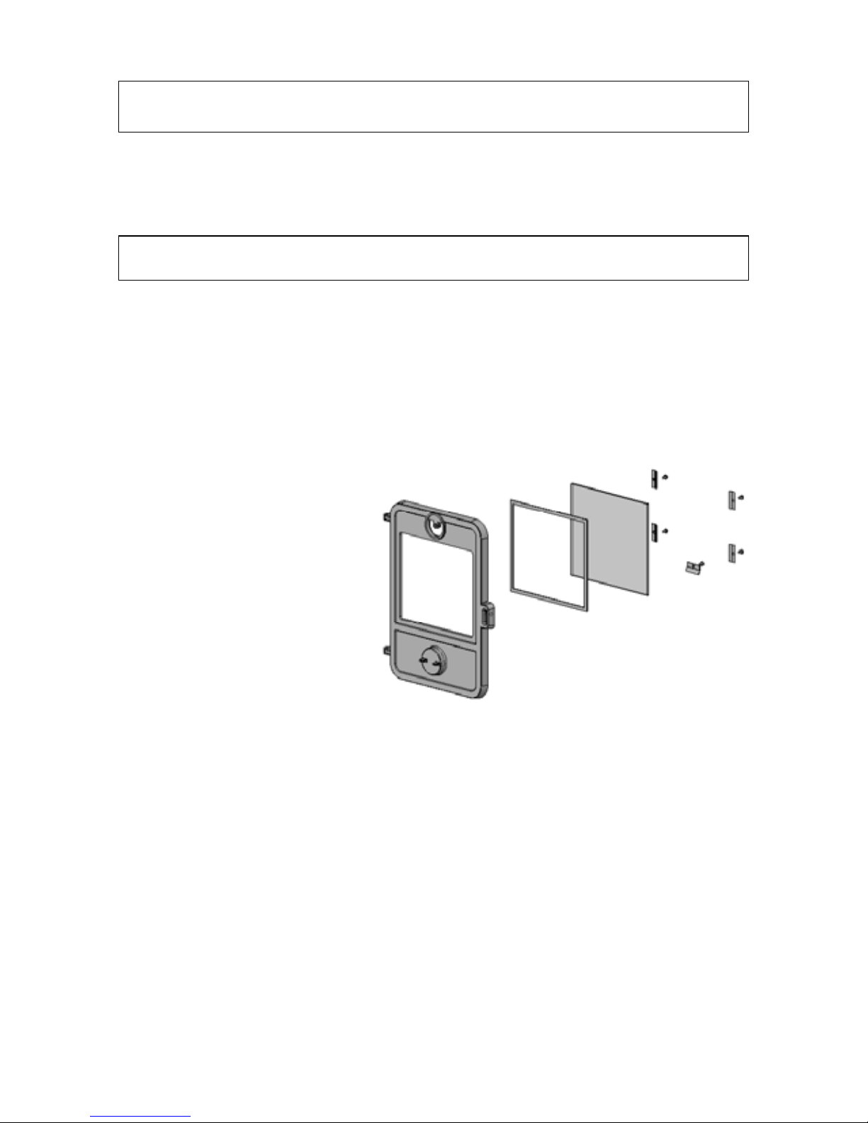
Installing the glass
Never install the glass when the stove is in function.
Ceramic glass replacement
Ceramic glass cannot be recycled because it has a higher melting point that ordinary glass.
If ceramic glass is mixed with ordinary glass, the raw material is spoiled, and the reclaiming
process may be halted. Take care that the ovenproof glass does not end up among ordinary
recycled waste. That will be a great benefit to the environment.
Note: Should be handed in to a recycling station as ceramic glass.
1. Lift the door off its hinges an place
face-down on a sheet of cardboard or
other non-abrasive fabric.
2. Unscrew the five bolts that secure
the glass. (In the event that a bolt
sheers off when being unscrewed,
remove the remaining body of the bolt
by drilling down its center with 1/8 inch
high speed steel drill bit. Smaller drill
bits may be successful, but do not use
a larger bit. Make sure the bit stays
away from the edges of the bolt - this
may damage the thread in the cast
iron).
3. Remove the old ceramic gaskets and clean up the surface underneath with wire wool or
emery paper to remove loose particles.
4. Place the new gasket material in position around the perimeter of the window area, making
sure to pinch them to the length in such a way that they make a continuous seal. Leave no gaps.
5. Place the new glass in position on the strips and screw home the fresh bolts and fitting by
hand.
6. Finally, give each of the bolts an extra half turn or so. The glass should held tight enough that
cleaning will not dislodge it. Do not over-tighten the bolts as this may put excessive pressure
on the glass, resulting in cracking - important!
Page 14

14
To reduce the risk of breaking the glass, avoid striking the glass or slamming the
door.
Internal service parts
The flame-path equipment - consisting of the ashpan, grate, firebricks, glass, baffle and flue
collar - are subject to the extremes of heat produced by the fire. From time to time, one or other
of these parts may need replacing as a matter of routine maintenance.
NOTE: The flame-path equipment, the ceramic rope and the paint finish are not
covered by guarantee.
All of these service parts can be bought from your morsø dealer, and we recommend that
damaged parts are replaced as soon as possible to avoid collateral damage.
The grate may be replaced by lifting it by its left hand edge and twisting it backwards. Dislocate
the riddling arm from the grate by feel from beneath the floor of the firebox. If you find this difficult
for any reason, raising the rectangular grate surround casting may help.
Should the baffle be distorted by an overfire, replace it as soon as possible. (This may be easier
if the firebricks are first removed).
Reasons for fast internal wear and tear
Persistent heavy firing
Soot and ashes left to accumulate
Ceramic Gasket
The gasket around the perimeter of the door may harden over a period of time. It should be
replaced if it becomes difficult to close the door or if air starts to leak in around the perimeter of
the door, causing the fire to become a little less controllable. A morsø rope gasket kit is available
from your stove supplier.
3.3 Cleaning the Stove and the Flue
Check for soot above the baffle plate and around the flue outlet every month or so to start with.
If the stove suddenly becomes sluggish, check for a soot fall around the flue collar or in the
flue/chimney. - at least once a year. Inspect every month.
Clean the flue/chimney - all the way from the stove to the flue terminal point above the house.
A good routine is to clean the flue after each heating season in any case, and inspect prior to the
season to ensure that bird’s nests or other blockages have not ocurred during the off season.
Page 15

15
Ash disposal
Empty the ashpan on a daily basis or as needed. Ash allowed to build up towards the underside
of the grate will trap heat and could cause premature failure of the grate.
Empty the ashpan according to this procedure:
When the door is closed, the grate can be operated by means of the riddling bar. Open the front
door, and use a shovel or poker to stir excess ash through the ash slots in the grate down into
the ash pan. Remove the ash pan, making sure to keep it level.
Dispose the ash in a metal container with a tight fitting lid.
The closed container of ashes should be placed on a noncombustible floor or on the ground,
well away from all combustible materials, pending final disposal. If the ashes are disposed of
by burial in soil or otherwise locally disperded, they should be retained in the closed container
until all cinders have thoroughly cooled.
Return the ash pan to its original position in the stove, and close.
Caution:
Never empty a stove in operation.
Never use your household or shop vacuum cleaner to remove ash from the stove;
Always remove and dispose of the ash properly.
Soot - Formation and Need for Removal
When coal is burned the products of combustion combine with moisture to form a soot residue
which accumulates on the flue lining. When ignited, this soot makes and extremely hot fire.
The chimney connectoe and chimney should be inspected at least once every months during
the heating season to determine if a soot buildup has occurred.
If soot has accumulated, it should be removed to reduce the risk of a chimney fire.
The inspection frequency:
Check for soot above the baffle plate and around the flue outlet every month.
Chimney sweeping
Inspect the system regularly during the heating season as part of a regular maintenance schedule.
To inspect the chimney, let the stove cool completely. Then, using a mirror, sight up through the
flue collar into the chimney flue. If you cannot inspect the flue system in this fashion, the stove
must be disconnected to provide better viewing access.
Clean the chimney using a brush the same size and shape as the flue liner. Run the brush up
and down the liner, causing any deposits to fall to the bottom of the chimney where they can
be removed through the clean-out door.
Clean the chimney connector disconnecting the sections, taking them outside, and removing
any deposits with a stiff wire brush. Reinstall the connetor sections after cleaning, being sure
to secure the joints between individual sections with sheet metal screws.
If you cannot inspect or clean the chimney yourself, contact your local Morsø Dealer or a
professional chimney sweep.
Page 16

16
If you do experience a chimney fire, act promptly and:
Close the air controls.
Get everyone out of the house.
Call the Fire Department.
Annual maintenance
Before the heating season, perform a thorough cleaning, inspection and repair:
Thoroughly clean the chimney and chimney connector.
Inspect the chimney for damage and deterioration. Replace weak sections of prefabricated
chimney. Have a mason make repairs to a masonry chimney.
Inspect the chimney connector and replace any damaged sections.
Check gasketing for wear or compression, and replace if necessary.
Check the glass for cracking; replace if needed.
Check door and handles for tightness. Adjust if needed.
3.4 Leaving the stove for extended periods
Important:
If the stove is to be left unused for any period of time, clean it out thoroughly and leave the
spinner slightly open to allow airflow. Make sure that the flue does not allow rainwater to come
anywhere near the stove; install a chimney cap, but do not block off the flue completely.
These measures should ensure there is a slight movement of air through the stove, and that the
body of the stove remains dry, right into the corners.
Any ash left within an unfired stove can attract moisture like blotting paper. If moisture is allowed
to settle within the stove, rust will form. Rust expands as it takes a grip. This can lead to undue
pressure on the stove joints, and this in turn may result in damage to the stove.
NOTE: It is best to thoroughly clean the stove after the heating season has concluded.
Adding a dessicant, such as kittle litter, into the ash pan helps absorb moisture during the
summer months. Be sure to remove this prior to the heating season.
Thank you for buying a Morsø stove.
We hope you have many years of carefree warmth in its company. Some initial experimentation
with loading and running techniques will decide your normal routine. If you have any problems
after this short learning phase, please refer to your stove dealer. Should they be unable to help
for any reason, please contact us in writing at the address on the front of this publication.
Page 17
17
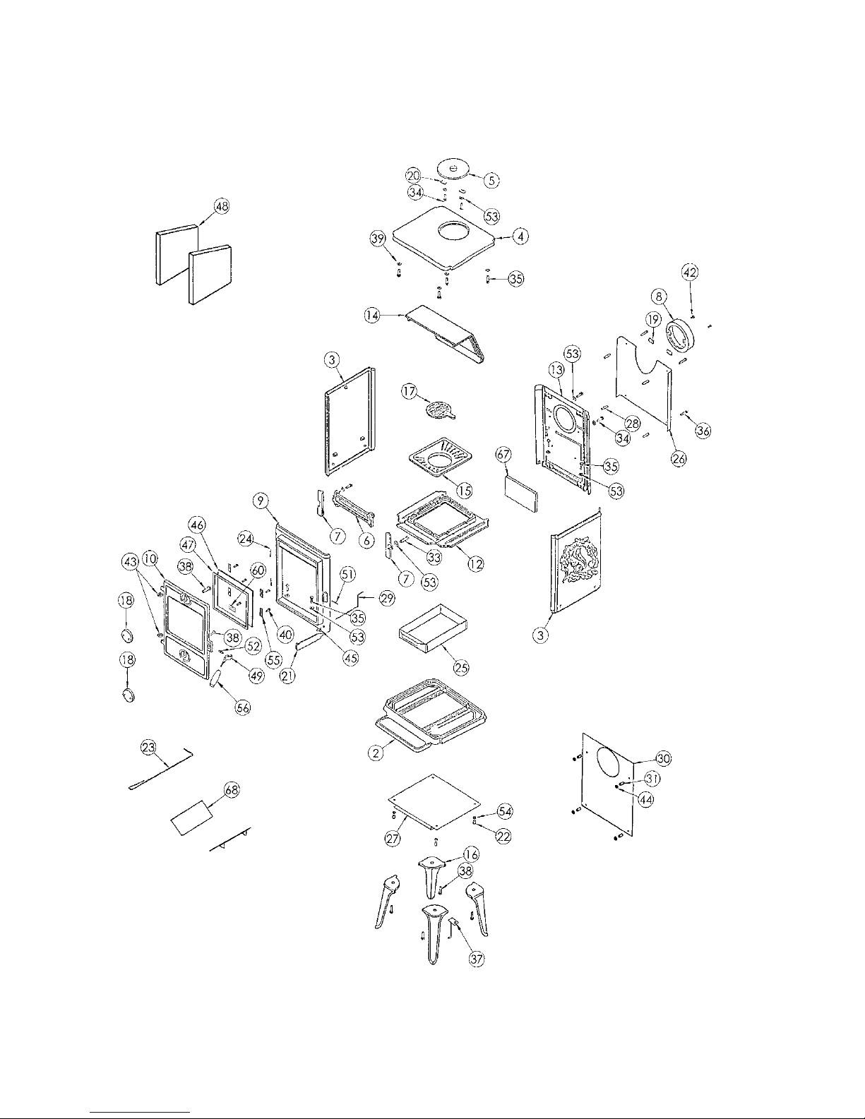
3.5 Parts diagram for the model Morsø 1410 squirrel Coal Heater
Page 18

18
3.6 Parts list for the model Morsø 1410 Squirrel Coal Heater
Pos.No. Parts
2 Base plate 44140121
3 Side plate w. squirrel 44140621
4 Top plate 44140721
5 Cover 44141021
6 Front grate 44141400
7 Attachment for front grate 44141600
8 Flue collar 44145921
9 Front frame 44142221
10 Door 44146021
12 Intermediate frame 44142400
13 Rear plate, outside 54142421
14 Baffle plate, cast iron 44141100
15 Frame for riddling grate 44203100
16 Leg 44203221
17 Riddling grate 44203300
18 Air valve 44241421
19 Fitting w. thread for flue collar 44256700
20 Fitting without thread f. cover 44256800
21 Handle for riddling grate 44262021
22 Distance tube 540614
23 Poker 541075
24 Hinge pin 541403
25 Ash tray 541405
26 Convection rear plate 54142521
27 Radiant shielding, bottom 541426
28 Distance tube 541439
29 Riddling bar 54344600
30 Radiant shielding, rear 541446
31 Distance tube 542635
33 Black steel set screw
34 Black steel set screw
35 Black steel set screw
36 Black steel set screw
37 Hanging for handle 71146021
38 Black steel set screw
39 Black washer
40 Bolt
42 Bolt
43 Brass washer
44 Clip pulley 746206
45 Knob for riddling grate 752619
46 Ceramic glass 790724
47 Tightening tape 79074400
48 Stone 790935
49 Locking device 79127200
51 Cotter pin 791868
52 Cotter pin 791869
53 Air slider washer
54 Washer
55 Glass fitting 54146261
56 Handle 79127300
60 Glass fitting 5414636 1
67 Stone 790934
68 Coal insert 44141800
Page 19

19
Page 20

20
Morsø Jernstøberi A/S - 05.07.2010 - 72146600
 Loading...