

Morrow Micro Decision MD-1, Micro Decision MD-2, Micro Decision MD-3 Service Manual
MICRO
DECISION
MODELS
MD-l
I MD-2 I MD-3
SERVICE
GUIDE
Copyright
1983
by
Morrow
Designs,
Incorporated
600
McCormick
Street
San
Leandro,
California
94577
All
rights
reserved.
THE
SERVICE PROCEDURES DESCRIBED
IN
THIS
DOCUMENT
ARE
TO
BE
PERFORMED
ONLY
BY
AUTHOR-
IZED
MORROW
DESIGNS DEALERSHIPS.
ONLY
QUALI-
FIED
SERVICE PERSONNEL SHALL PERFORM
THE
REPAIRS~·······_--UU.AJ:,TFTC.ATTON··M.AY·····
··BE·····OBTAINED·········BY
SATISFACTORY
COMPLETION
OF
A
MORROW
DESIGNS
SERVICE SEMINAR.
No
part
of
this
publication
may
be
reproduced,
transmitted,
stored
in
a
retrieval
system
or
translated
into
any
language
or
computer
language,
in
any
form
or
by
any
means,
eletronic,
mechanical,
magnetic,
optical,
chemical,
manual,
or
otherwise,
without
the
prior
written
permission
of
Morrow
Designs,
Inc.
No
representations
or
warranties,
express
or
implied,
are
made
with
respect
to
the
contents
hereof,
including,
but
not
limited
to,
the
implied
warranty
of
merchantability
or
fitness
for
a
particular
purpose.
Further,
Morrow
Designs
reserves
the
right
to
revise
this
publication
and
to
make
changes
from
time
to
time
in
the
contents
hereof
without
obligation
to
notify
any
person
of
such
revision.
Diagnostics
II
is
a
product
of
SuperSoft,
Incorporated.
The
documentation
contained
herein
for
this
product
is
reproduced
with
the
permission
of
SuperSoft.
PART
I - TECHNICIAN'S REFERENCE:
COMPONENT
ID
AND
DISASSEMBLY
PREFACE
The
Micro
Decision
Service
Guide
is
organized
in
two
distinct
parts.
Part
I
serves
as
a
technician's
reference
guide;
the
modular
assembly
of
the
Micro
Decision
is
discussed
in
detail,
and
the
disassembly
procedures
for
each
module
is
provided.
Troubleshooting
and
parts
replacement
is
also
covered
in
Part
I.
Part
II,
Diagnostics
II
User's
Manual,
follows
the
Customer
Service
Bulletin
Index.
This
part
of
the
Micro
Decision
Service
Guide
details
the
testing
of
each
major
Micro
Decision
component.
The
Morrow
Designs
Micro
Decision
computer
system
is
designed
for
serviceability.
A
reduced
part
count
and
modular
assembly
approach
contribute
to
reliability
and
ease
of
service.
The
Central
Processing
Unit,
memory
circuits,
communications
port
and
all
support
electronics
reside
on
a
single
printed
circuit
board
("motherboard").
One
power
supply
assembly
provides
all
DC
operating
voltages
to
the
motherboard
and
the
internal
disk
drives.
The
motherboard,
power
supply,
and
disk
drives
are
typically
replaced
as
complete
units.
Thus
repairs
can
usually
be
performed
with
a
minimum
of
troubleshooting
for
you
and
downtime
for
the
owner.
No
special
tools
are
required,
beyond
normal
hand
tools.
A
digital
voltmeter
is
needed
for
power
supply
troubleshooting
and
cable
continuity
tests.
User-selectable
options
are
limited
to
baud
rates,
hardware/software
printer
handshaking,
and
terminal/modem
selection
for
the
RS-232
connectors.
These
are
described
in
the
Micro
Decision
User's
Guide.
Refer
to
the
User's
Guide
for
an
introduction
to
the
system
and
operating
instructions.
The
intent
of
this
manual
is
to
guide
you
through
module
replacements.
To
this
end,
disassembly
procedures,
troubleshooting
flowcharts,
and
SuperSoft's
Diagnostics
II
documentation
are
included.
If
you
attempt
to
perform
repairs
at
a
component
level,
you
do
so
at
your
own
risk
and
with
the
knowledge
that
doing
so
voids
any
remaining
factory
warranty
on
the
unit.
TAB
L E o F
CON
TEN
T S
1.
TOOLS REQUIRED FOR DISASSEMBLy
•••••••••••••••••••••••••••
1-1
CO~R
~O"AL
••••••••••••••••••••••••••••••••••••••••••••
2.
2.1.
2.2.
Revision
A
Chassis
••••••••••
Revision
Band
C
Chassis
••••••••••
2-1
2-2
2-4
3.
DISK
3.1.
3.2.
3.3.
3.4.
DRIVE CONFIGURATION
AND
REMO"AL
•••••
MDIand
MD
II
-
Revision
A
Chassis.
MD
III
-
Revision
A
Chassis
••••••••••••••••
MDIand
MD
III
-
Revision
Band
C
Chassis
••
MD
II
Revision
Band
C
Chassis
•••••••••••
3-1
3-1
3-2
3-2
3-4
4.
POWER
SUPPLY
REMO"AL
•••••••••••••••••••••••••••••
4.1.
Revision
A
Chassis........
•
••••
4.2.
Revision
Band
C
Chassis..
•
••••
4-1
4-1
4-1
MOTHERBOARD
RE"ISIONS
•••••
5.
5.1.
5.2.
5.3.
Revision
1.1
Details.
Motherboard
Removal
•.
Revision
2.0
Features
•.
5.3.1.
Parallel
Port
••.
5.3.2.
Serial
Ports
••••••••••
5.3.3.
40
Pin
I/O
Connector
••
5.3.4.
ROM
Diagnostics
•••••••
5.3.5.
Drive
Expansion
•••••••
5.3.6.
Disk
Drive
Connector
••
5-1
5-1
5-3
5-3
5-7
5-8
.5-16
.5-17
.5-18
.5-19
6-1
6-1
6-1
6-5
6-5
Tools
Required
••••••••••••••••••
Troubleshooting
Flowchart
••••••••••••••••••••••
Measuring
Power
Supply
Voltages
••••••••••••••••
Tips
on
Troubleshooting
Power
Supply
Problems
••••
TROUBLESHOOTING PROCEDURES
••••••••••
6.1.
6.2.
6.3.
6.4.
6.
7.
REPLACEMENT PARTS
.......................................
7-1
8.
CUSTOMER
SERVICE BULLETIN INDEX
••••••••••
8-1
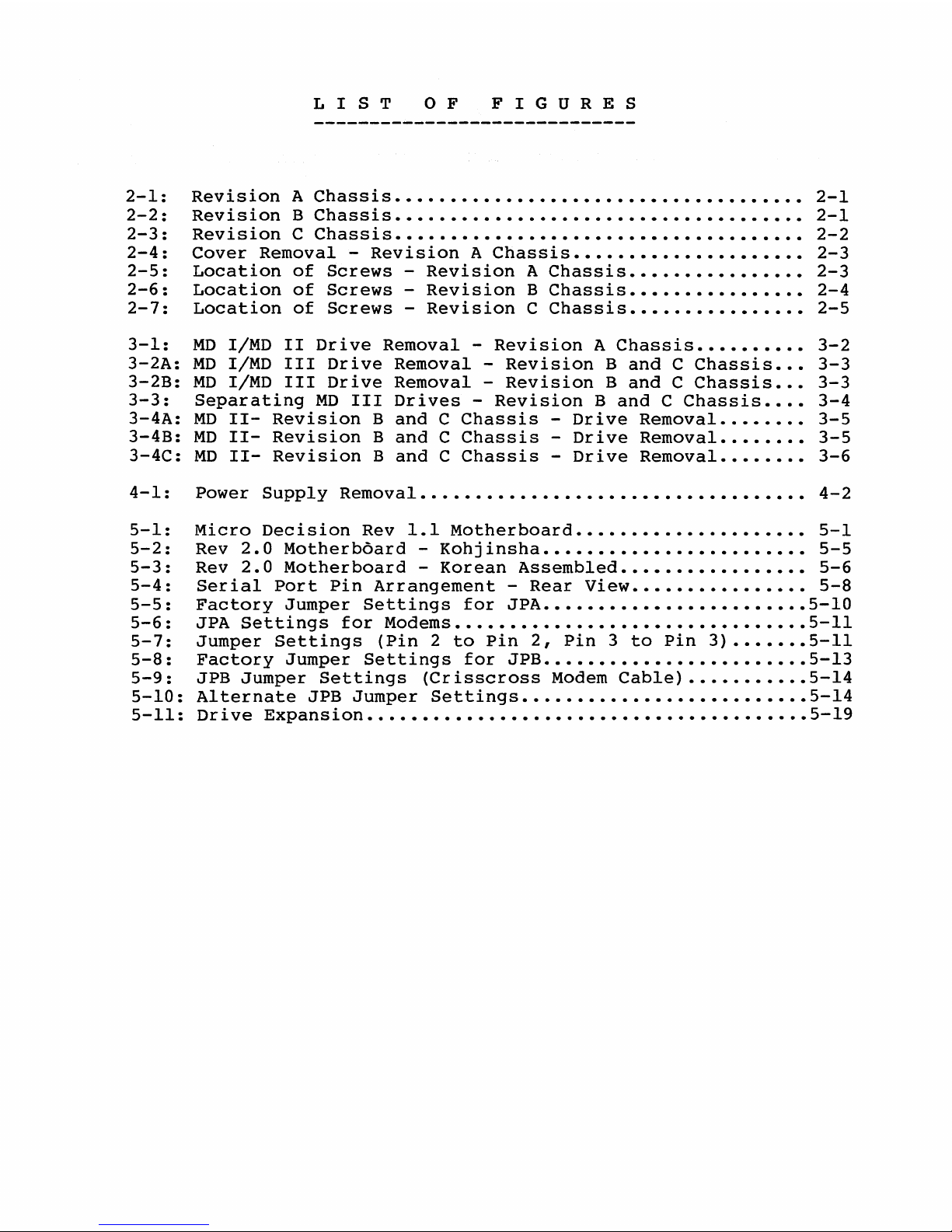
LIS
T o F
FIG
U
RES
2-1:
2-2:
2-3:
2-4:
2-5:
2-6:
2-7:
3-1:
3-2A:
3-2B:
3-3:
3-4A:
3-4B:
3-4C:
4-1:
Revision
A
Chassis
•••••••••••••••••••••••••••••••••••••
Revision
B
Chassis
•••.•••••••••••••••••••••••••••••••••
Revision
C
Chassis
•••••••••••••••••••••••••••••••••••••
Cover
Removal
-
Revision
A
Chassis
•••••••••••••••••••••
Location
of
Screws
-
Revision
A
Chassis
••••••••••••••••
Location
of
Screws
-
Revision
B
Chassis
••••••••••••••••
Location
of
Screws
-
Revision
C
Chassis
••••••••••••••••
MD
I/MD
II
Drive
Removal
-
Revision
A
Chassis
••••••••••
MD
I/MD
III
Drive
Removal
-
Revision
Band
C
Chassis
•••
MD
I/MD
III
Drive
Removal
-
Revision
Band
C
Chassis
•••
Separating
MD
III
Drives
-
Revision
Band
C
Chassis
••.•
MD
11-
Revision
Band
C
Chassis
-
Drive
Removal
••••••••
MD
11-
Revision
Band
C
Chassis
-
Drive
Removal
••••••••
MD
11-
Revision
Band
C
Chassis
-
Drive
Removal
••••••.•
Power
Supply
Removal
•.•••.•••••••.••••..•••••••••••••••
2-1
2-1
2-2
2-3
2-3
2-4
2-5
3-2
3-3
3-3
3-4
3-5
3-5
3-6
4-2
5-1:
5-2:
5-3:
5-4:
5-5:
5-6:
5-7:
5-8:
5-9:
5-10:
5-11:
Micro
Decision
Rev
1.1
Motherboard
•••••••••••••••••••••
5-1
Rev
2.0
Motherboard
-
Kohjinsha
••••••••••••••••••••••••
5-5
Rev
2.0
Motherboard
-
Korean
Assembled
•••••••••••••••••
5-6
Serial
Port
Pin
Arrangement
-
Rear
View
••••••••••••••••
5-8
Factory
Jumper
Settings
for
JPA
••••••••••••••••••••••••
5-10
JPA
Settings
for
Modems
••••••••••••••••••••••••••••••••
5-11
Jumper
Settings
(Pin
2
to
Pin
2,
Pin
3
to
Pin
3)
•••••••
5-11
Factory
Jumper
Settings
for
JPB
••••••••••••••••••••••••
5-13
JPB
Jumper
Settings
(Crisscross
Modem
Cable)
•••••••••••
5-14
Alternate
JPB
Jumper
Settings
•••.••••••••••••••••••••••
5-14
Drive
Expansion
••••••••••••••••••.•••••••••••••••••••••
5-19
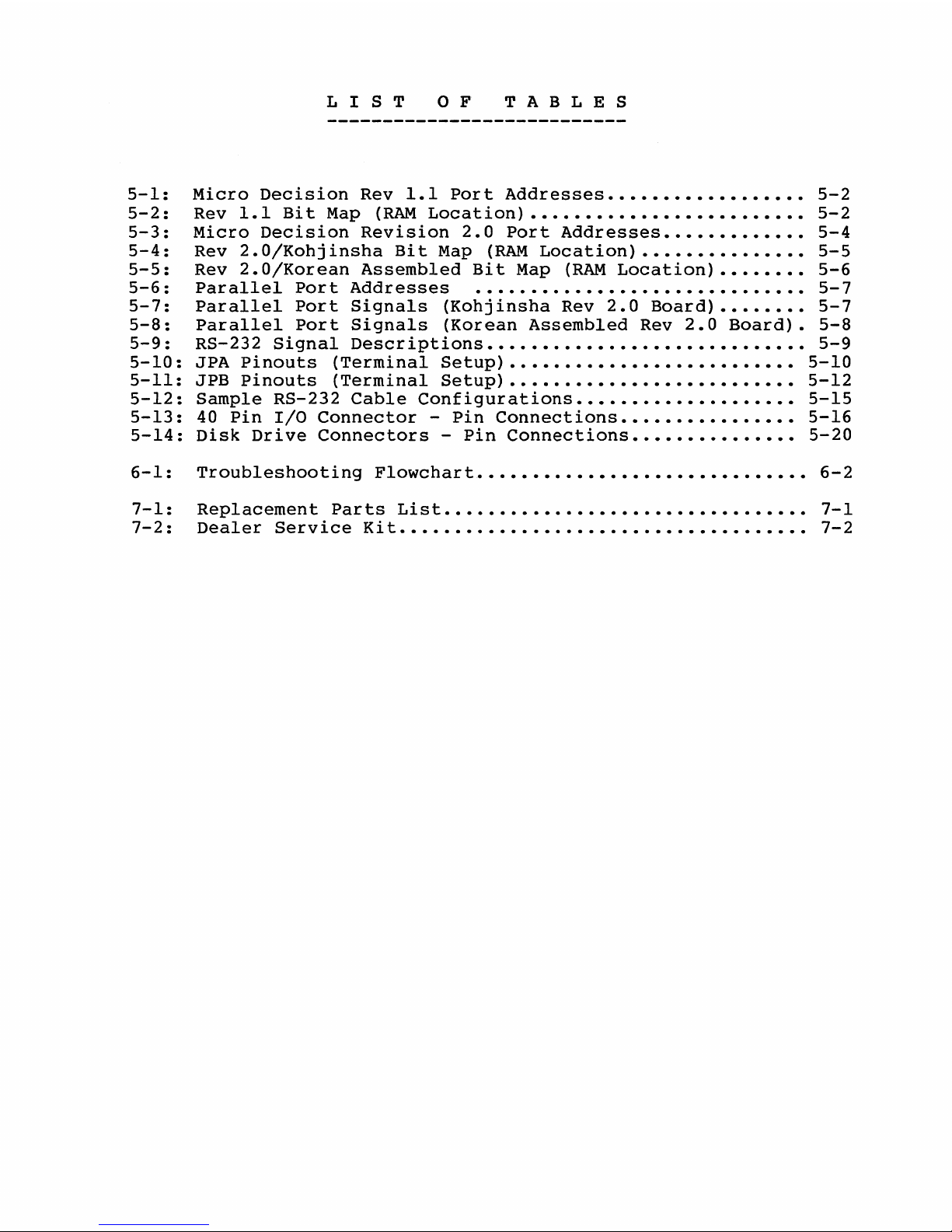
LIS
T o F
TAB
L E S
5-1:
5-2:
5-3:
5-4:
5-5:
5-6:
5-7:
5-8:
5-9:
5-10:
5-11:
5-12:
5-13:
5-14:
Micro
Decision
Rev
1.1
Port
Addresses
••••••••••••••••••
5-2
Rev
1.1
Bit
Map
(RAM
Location)
•••••••••••••••••••••••••
5-2
Micro
Decision
Revision
2.0
Port
Addresses
•••••••••••••
5-4
Rev
2.0/Kohjinsha
Bit
Map (RAM
Location)
•••••••••••••••
5-5
Rev
2.0/Korean
Assembled
Bit
Map
(RAM
Location)
••••••••
5-6
Parallel
Port
Addresses
••••••••••••••••••••••••••••••
5-7
Parallel
Port
Signals
{Kohjinsha
Rev
2.0
Board)
••••••••
5-7
Parallel
Port
Signals
(Korean
Assembled
Rev
2.0
Board).
5-8
RS-232
Signal
Descriptions
•••••••••••••••••••••••••••••
5-9
JPA
Pinouts
{Terminal
Setup)
••••••••••••••••••••••••••
5-10
JPB
Pinouts
(Terminal
Setup)
•••••.••••••••••••••••••••
5-12
Sample
RS-232
Cable
Configurations
••••••••••••••••••••
5-15
40
Pin
I/O
Connector
-
Pin
Connections
••••••••••••••••
5-16
Disk
Drive
Connectors
-
Pin
Connections
•••••••••••••••
5-20
6-1:
Troubleshooting
Flowchart
••••••••••••••••••••••••••••••
6-2
7-1:
Replacement
Parts
List
•••••••••••••••••••••••••••••••••
7-1
7-2:
Dealer
Service
Kit
••••.••.••..••.••••.••.••.••••••••••.
7-2
Part
I-Section
1:
Tools
Required
for
Disassembly
1.
TOOLS
REQUIRED
FOR
DISASSEMBLY
(09/23/83)
You
will
need
a
Phillips
screwdriver,
preferably
size
12
and
magnetic..
Keep
any
magnetized
tools
away
from
diskettes
that
contain
valuable
files.
To
help
insure
against
callbacks,
you
should
wear
a
grounding
wriststrap
that
is
connected
to
the
Micro
Decision
chassis
whenever
you
handle
the
mother
board.
1-1
Part
I-Section
2:
Cover
Removal
(09/23/83)
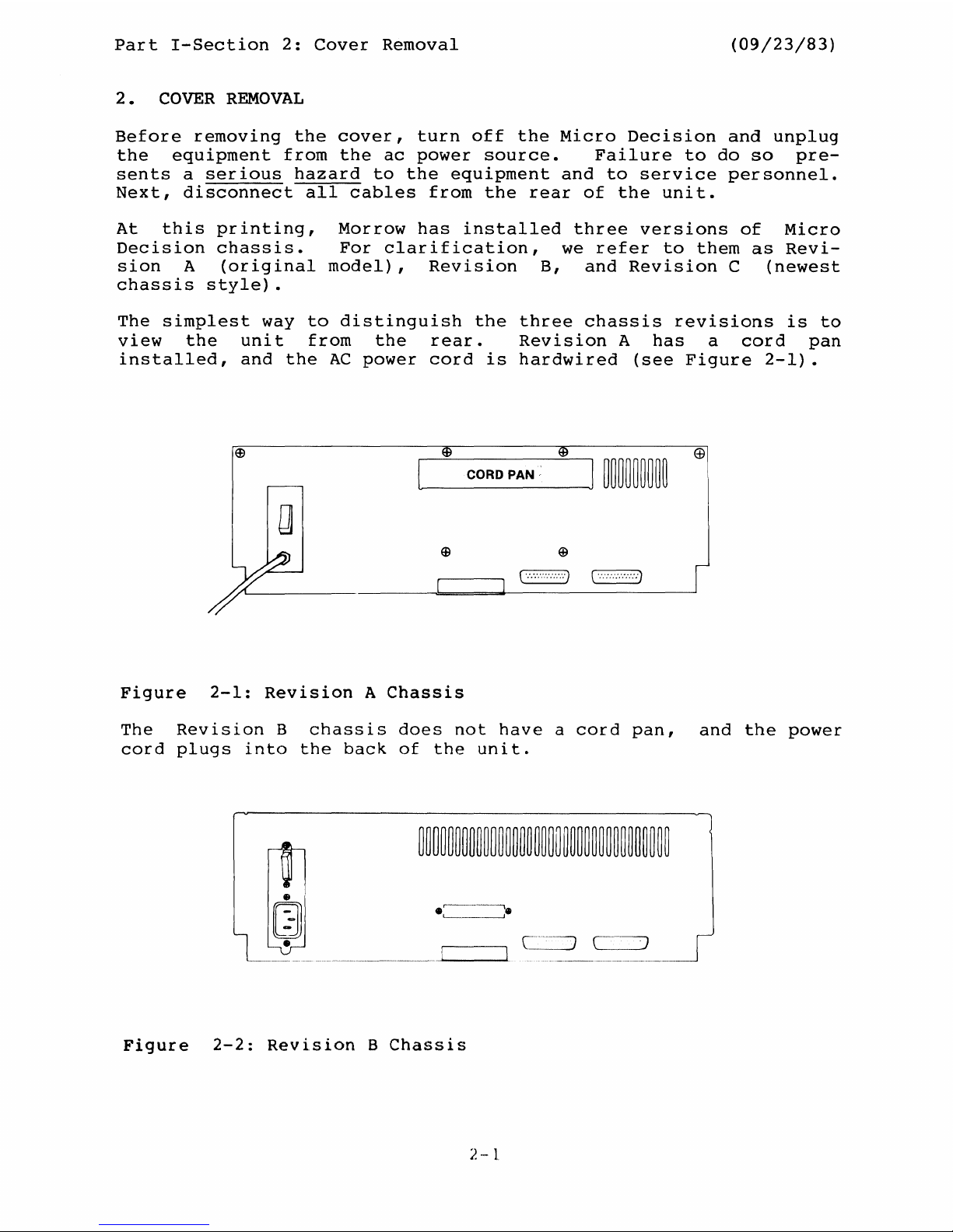
2 • COVER REMOVAL
Before
removing
the
cover,
turn
off
the
Micro
Decision
and
unplug
the
equipment
from
the
ac
power
source.
Failure
to
do
so
pre-
sents
a
serious
hazard
to
the
equipment
and
to
service
personnel.
Next,
disconnect
all
cables
from
the
rear
of
the
unit.
At
this
printing,
Morrow
has
installed
three
versions
of
Micro
Decision
chassis.
For
clarification,
we
refer
to
them
as
Revi-
sion
A
(original
model),
Revision
B,
and
Revision
C
(newest
chassis
style).
The
simplest
way
to
distinguish
the
three
chassis
reVlSlons
is
to
view
the
unit
from
the
rear.
Revision
A
has
a
cord
pan
installed,
and
the
AC
power
cord
is
hardwired
(see
Figure
2-1).
@
c::==:=J
c==J
Figure
2-1:
Revision
A
Chassis
The
Revision
B
chassis
does
not
have
a
cord
pan,
and
the
power
cord
plugs
into
the
back
of
the
unit.
Figure
2-2:
Revision
B
Chassis
2
.,~
'1
Part
I-Section
2:
Cover
Removal
(09/23/83)
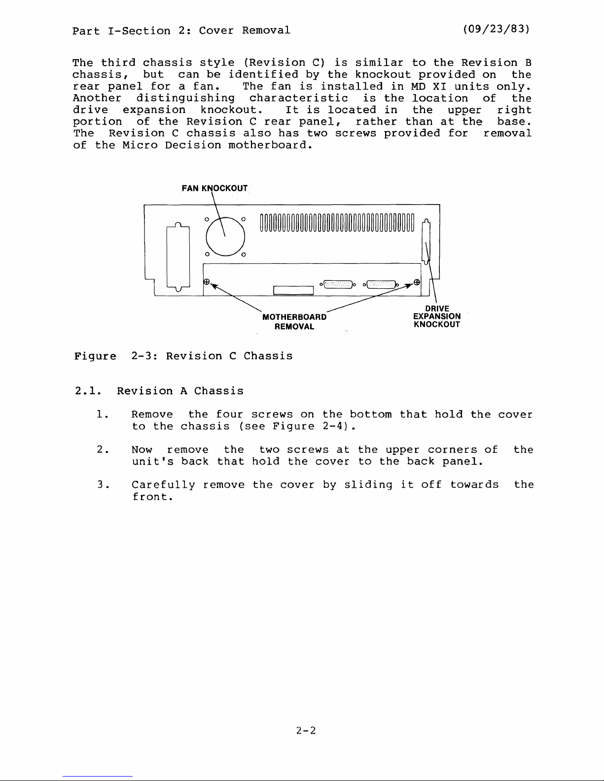
The
third
chassis
style
(Revision
C)
is
similar
to
the
Revision
B
chassis,
but
can
be
identified
by
the
knockout
provided
on
the
rear
panel
for
a
fan.
The
fan
is
installed
in
MD
XI
units
only.
Another
distinguishing
characteristic
is
the
location
of
the
drive
expansion
knockout.
It
is
located
in
the
upper
right
portion
of
the
Revision
C
rear
panel,
rather
than
at
the
base.
The
Revision
C
chassis
also
has
two
screws
provided
for
removal
of
the
Micro
Decision
motherboard.
FAN KNOCKOUT
MOTHERBOARD
REMOVAL
Figure
2-3:
Revision
C
Chassis
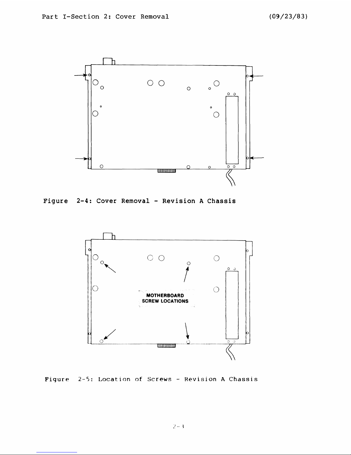
2.1.
Revision
A
Chassis
1.
Remove
the
four
screws
on
the
bottom
that
hold
the
cover
to
the
chassis
(see
Figure
2-4).
2.
Now
remove
the
two
screws
at
the
upper
corners
of
the
unit's
back
that
hold
the
cover
to
the
back
panel.
3.
Carefully
remove
the
cover
by
sliding
it
off
towards
the
front.
2-2
Part
I-Section
2:
Cover
Removal
(09/23/83)
00
o
o
o
o 0
o
o
o
o
o
o 0
Figure
2-4:
Cover Removal -
Revision
A
Chassis
(
''''~
,)
()
o
!
MOTHERBOARD
SCREW LOCATIONS
()
o
,,)
/
()
."
..
""""
•.
",~-'""~,
..
"
...
"
...
,~
..
"
..
"",,
....
,"".
"-----."-,,.,,---,,,,--,,------
1111111
1111
III
!III"""
o
'.J
--~
Figure
2
5:
Location
of
Screws
-
Revision
A
Chassis
Part
I-Section
2:
Cover
Removal
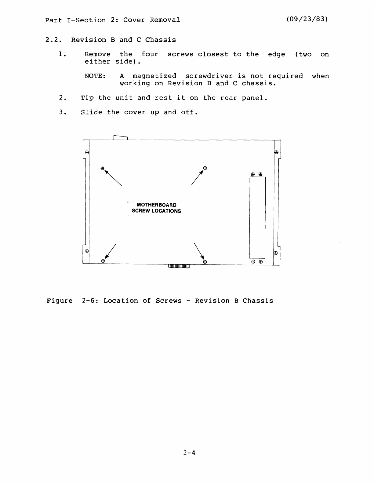
2.2.
Revision
Band
C
Chassis
(09/23/83)
1.
Remove
the
four
screws
closest
to
the
edge
(two
on
either
side).
NOTE: A
magnetized
screwdriver
is
not
required
when
working
on
Revision
Band
C
chassis.
2.
Tip
the
unit
and
rest
it
on
the
rear
panel.
3.
Slide
the
cover
up
and
off.
r---,
®
~
e",
/e
~
MOTHERBOARD
SCREW LOCATIONS
@
I
\
E!)
'----
E9
~
@
Figure
2-6:
Location
of
Screws
-
Revision
B
Chassis
2·-4
Part
I-Section
2:
Cover
Removal
(09/23/83)
r---,
ffi
~
'"
/(9
~
MOTHERBOARD
SCREW LOCATIONS
EB
~
L.--
@@
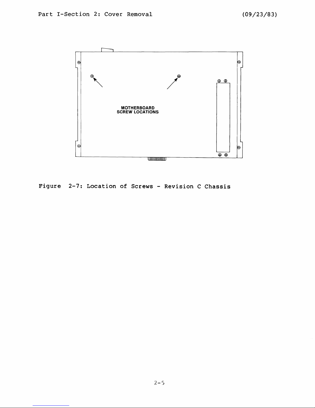
Figure
2-7:
Location
of
Screws
-
Revision
C
Chassis
Part
I-Section
3:
Disk
Drive
Configuration
and
Removal
(09/23/83)
3.
DISK
DRIVE CONFIGURATION
AND
REMOVAL
There
are
three
drive
configurations
for
the
Micro
Decision:
MD
I -
One
3/4
high,
single
sided,
5
1/4
inch
floppy
drive,
mounted
at
the
left
(as
you
face
the
unit)
MD
II
- Two
3/4
high,
single
sided,
5
1/4
inch
floppy
drives,
mounted
side
by
side
MD
III
- Two
1/2
high,
double
sided
floppy
drives,
stacked
(drive
B
mounted
above
drive
A)
in
the
left
half
of
the
unit
(as
you
face
the
front)
Drive
removal
depends
on
the
configuration
of
the
drives
and
the
type
of
chassis
in
which
these
drives
are
installed.
NOTE:
When
removing
MD
II
or
MD-
III
drives
from
a
Revision
1.1
motherboard,
it
is
very
important
that
you
mark
disk
drives
as
A
or
B,
since
they
must
go
back
in
the
same
positions
from
which
they
came.
The
best
method
is
to
place
a
piece
of
masking
tape
on
the
B
drive
with
a
note
"next
to
power
supply".
3.1.
MDIand
MD
II
-
Revision
A
Chassis
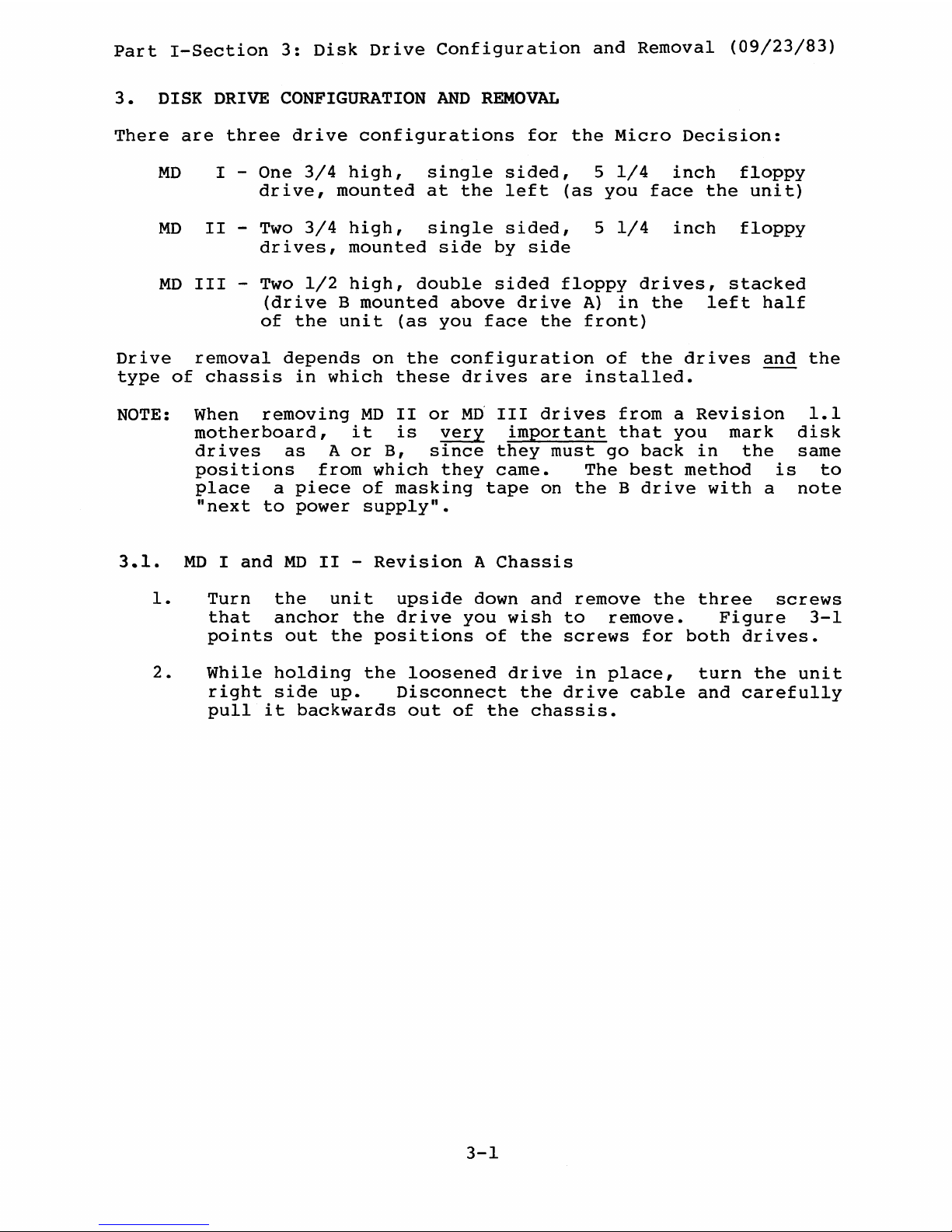
1.
Turn
the
unit
upside
down
and
remove
the
three
screws
that
anchor
the
drive
you
wish
to
remove.
Figure
3-1
points
out
the
positions
of
the
screws
for
both
drives.
2.
While
holding
the
loosened
drive
in
place,
turn
the
unit
right
side
up.
Disconnect
the
drive
cable
and
carefully
pull
it
backwards
out
of
the
chassis.
3-1

Part
I-Section
3:
Disk
Drive
Configuration
and
Removal
(09/23/83)
o
0'--
00
II
~o
o 0
--
....
0
o 0
o
o
o 0
Figure
3-1:
MD
I/MD
II
Drive
Removal
-
Revision
A
Chassis
3.2.
MD
III
-
Revision
A
Chassis
1.
Follow
the
instructions
provided
for
MD
I
and
MD
II
drive
removal
(Section
3.1).
2.
Remove
the
strap
which
holds
the
two
drives
together.
Remember
to
mark
one
or
both
of
the
drives:
drive
B
must
be
reinstalled
on
top
of
drive
A.
3.3.
MDIand
MD
III
-
Revision
Band
C
Chassis
1.
Disconnect
the
flat
ribbon
cable(s)
from
the
connector(s)
on
the
drive(s).
Then
disconnect
the
cable(s)
to
the
motherboard.
For
MD
III
configurations,
we
recommend
that
you
mark
the
cables
for
drive
B
to
identify
them
when
reinstalling
the
drive.
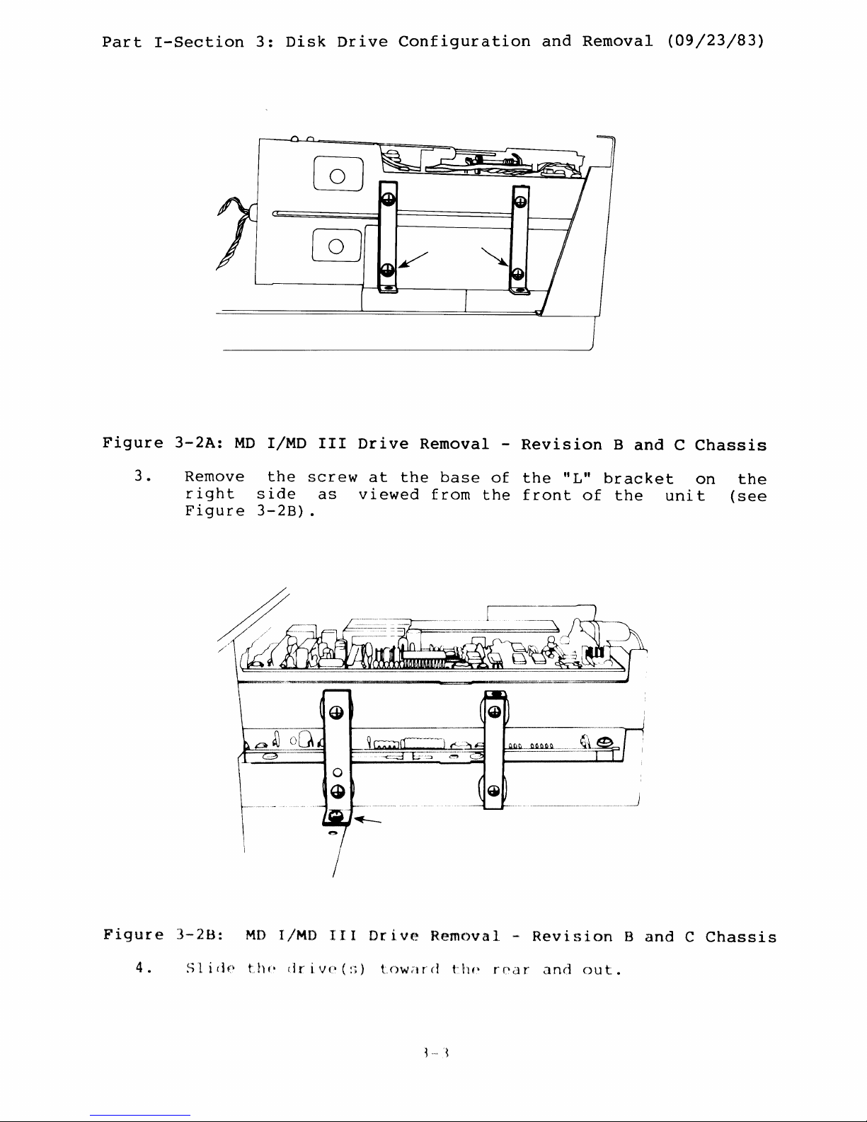
2.
Remove
the
two
bottom
screws
from
the
brackets
on
the
left
(see
Figure
3-2A).
3-2
Part
I-Section
3:
Disk
Drive
Configuration
and
Removal
(09/23/83)
Figure
3-2A:
MD
I/MO
III
Drive
Removal
-
Revision
Band
C
Chassis
3 •
Remove
the
screw
at
the
base
of
the
ilL"
bracket
on
right
side
as
viewed
from
the
front
of
the
unit
Figure
3-2B).
the
(see
Figure
3-2B:
MD
I/MD
III
Drive
R,emc)val
,-
I~evisi.on
Band
C
Chassis
4 •
~.:;,
1 i d
f'
t"
II(' d r
i,
v(' (:;) t
()w
tt
r
cl
til
p r
par
';:1
nd()u t .
Part
I-Section
3:
Disk
Drive
Configuration
and
Removal
(09/23/83)
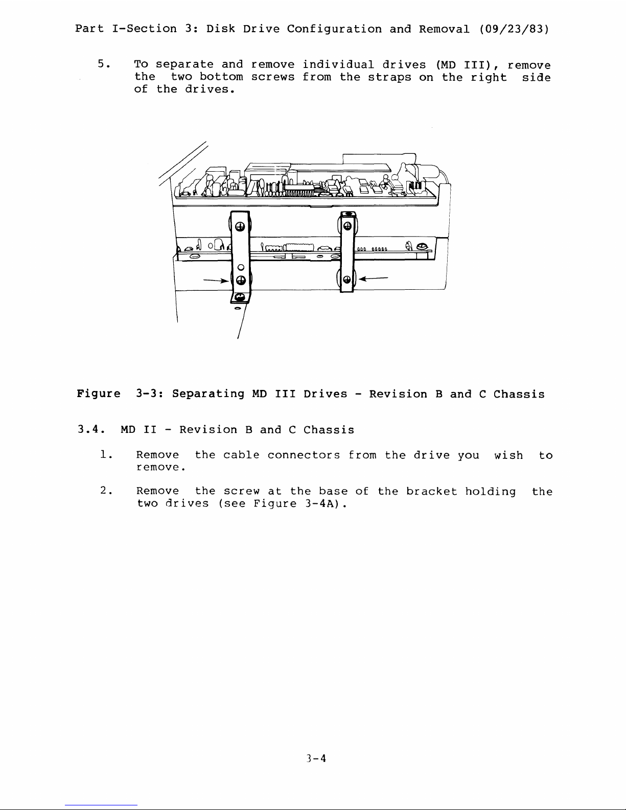
5.
To
separate
and
remove
individual
drives
(MD
III),
remove
the
two
bottom
screws
from
the
straps
on
the
right
side
of
the
drives.
Figure
3-3:
Separating
MD
III
Drives
-
Revision
Band
C
Chassis
3.4.
MD
II
-
Revision
Band
C
Chassis
1.
Remove
the
cable
connectors
from
the
drive
you
wish
to
remove.
2.
Remove
the
screw
at
the
base
of
the
bracket
holding
the
two
drives
(see
Figure
3-4A).
3-4
 Loading...