

Morrow MDT 50 Service Manual
MDT50
VIDEO DISPLAY TERMINAL
SERVICE
MANUAL
Copyright
(C) 1983
by
Morrow
Inc.
All
rights
reserved.
No
part
of
this
publication
may
be
reproduced,
transmitted,
transcribed,
stored
in
a
retrieval
system,
or
translated
into
any
language
or
computer
language,
in
any
form
or
by
any
means,
electronic,
mechanical,
magnetic,
optical,
chemical,
manual
or
otherwise,
without
prior
written
permission
of
Morrow
Inc.
DISCLAIMER
No
representations
or
warranties,
express
or
implied,
are
made
with
respect
to
the
contents
hereof,
including,
but
not
limited
to,
the
implied
warranty
of
merchantability
or
fitness
for
a
particular
purpose.
Further,
Morrow
Inc.,
reserves
the
right
to
revise
this
publication
and
to
make
changes
from
time
to
time
in
the
content
hereof
without
obligation
to
notify
any
person
of
such
revision.
Morrow
600 McCormick
St.
San
Leandro,
CA
94577
TABLE
OF
CONTENTS
SECTION
o
--
INTRODUCTION
Scope
of
this
Manual
WARNING
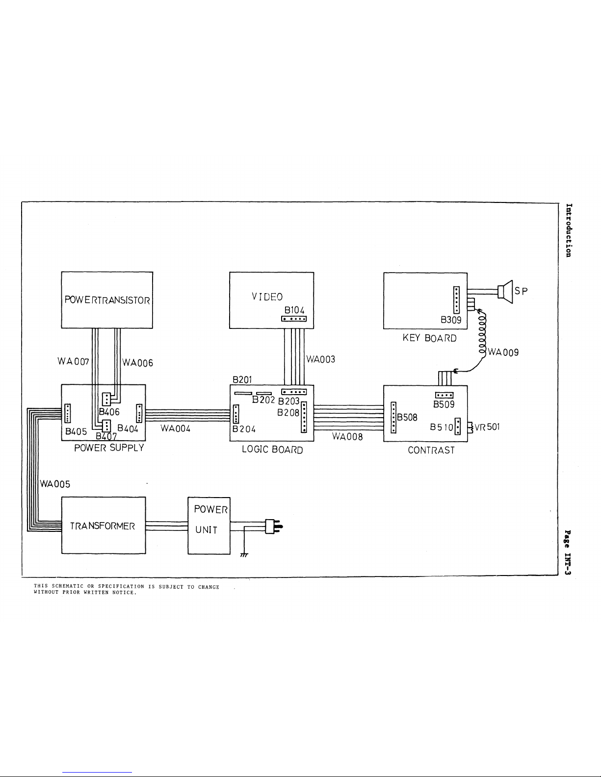
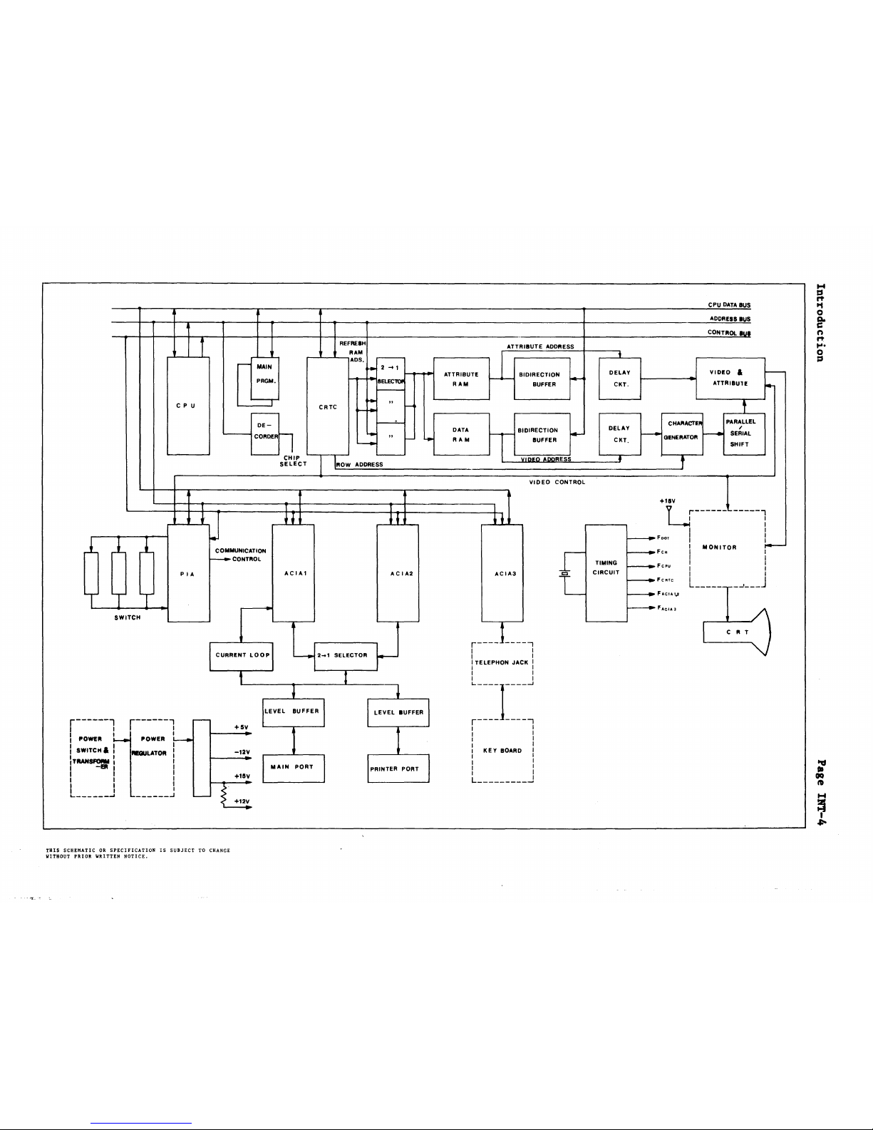
Components
Block
Diagram
Interconnections
Theory
of
Operation
Terminal
Operation
Data
Paths
Quick
Check-out
1
--
THE
VIDEO
BOARD
Theory
of
Operation
Video
Signal
Vertical
Synch
Horizontal
Synch
Miscellaneous
Controls
Troubleshooting
Components
Test
Points,
Typical
Waveforms
&
Signal
Levels
2
--
THE
MAIN LOGIC
BOARD
Theory
of
Operation
Test
Points,
Typical
Waveforms
&
Signal
Levels
3
--
THE
KEYBOARD
Theory
of
Operation
Test
Points,
Typical
Waveforms
&
Signal
Levels
4
--
THE
POWER
SUPPLY
Theory
of
Operation
Troubleshooting
Components
Test
Points,
Typical
Waveforms
&
Signal
Levels
PAGri
INT-l
INT-l
INT-l
INT-3
INT-4
INT-5
INT-5
INT-6
INT-7
VI})-l
VID-l
VID-l
VID-l
VID-;l
VID-;l
VID-2
VID-6
MLB-l
MLB-l
KYB-l
KYB-l
PWR-l
PWR-l
PWR-l
PWR-3
5
--
MAINTENANCE
The
Monitor
Unit
General
Replacing
the
CRT
tube
The
Keyboard
Unit
MTC-l
MTC-l
MT<.;-l
MTC-2
Introduction
Scope
of
this
Manual
IRnODUCTIOB
Page
INT-l
This
Manual
presents
details
of
the
circuitry
and
data
paths
of
the
Morrow
MDT50
Video
Display
Terminal)
along
with
information
on
typical
wave-
forms
and
signal
levels,
to
allow
service
personnel
to
troubleshoot
and
repair
the
terminal,
as
needed.
Familiarity
with
the
Morrow
MDT50·
User's
Manual
is
assumed.
While
every
effort
has
been
made
to
assure
that
the
information
contained
herein
is
accurate
and up
to
date)
Morrow
Designs,
Inc.
reserves
the
right
to
make
engineering
changes
and
appropriate
parts
substitutions
without
prior
notice
in
the
interests
of
increased
and
improved
performance.
> > > >
WARRING
< < < <
CRITICAL
COMPORDT
WARBlRG:
SERVICEMAR
WARRING:
This
product
contains
components
which
are
critical
for
X-Radiation
Safety.
See
Service
Manual
for
proper
replacement.
Normal 2nd Anode
Voltage
is
12
KV
at
Zero beam
current,
AC
120V
input,
and must
lOT
exceed
13
KV
under
any
operating
conditions.
To
measure
2nd Anode
Voltage,
use
High Impedance
meter.
Connect
(-)
to
chassis,
use
a High
Voltage
lead
from
(+)
to
2nd Anode.
Components
of
the
Morrow
MDTSO
Terminal
External
From
an
outside
viewpoint)
the
Morrow
MDTSOconsists
of
two
units:
The
Monitor
Unit,
containing
the
CRT)
power
supply)
and
control
circuits;
and
the
Keyboard
Unit,
containing
the
physical
keyboard)
its
decoding
circuitry,
and
circuits
for
communicating
with
the
Monitor
Unit.
The
Keyboard
and
Monitor
Units
are
connected
by
a
coiled
telephone
handset
cord
with
7,62
mm
(0.3
in)
male
plugs
at
each
end. Power
is
supplied
via
a
3-wire
grounded
cord,
terminated
by a
U.S.
NEMA
standard
plug
(which
may
be
replaced
to
suit
local
power
system
requirements).
Communications
with
a Host
computer
or
modem
and a
printer
are
provided
via
asynchronous
RS-232
communication
via
two
female
DB-25
receptacles
on
the
rear
of
the
Monitor
Unit.
Controls
are
provided
on
the
Monitor
Unit
for
Power
ON/OFF,
Contrast,
and
setting
operating
parameters.
Introduction
Internal
Internally,
the
Morrow
MDT50
consists
of:
Page INT-2
~
A
Transformer
and
Voltage
Selector
Switch
for
converting
115V
or
230V
AC
mains
power
to
10.5V
AC,
16.7V
AC,
and
21.3V
AC.
~
A Power
Supply
board,
with
rectifiers
and
voltage
regulators,
to
pro-
duce
+5V,
+15V,
and
-12V
DC
[regulated
to
±IO%].
~
A Main
Logic
Board,
with
a 68A02
Microprocessor,
16k
of
EPROM-resident
firmware,
2k
of
character
storage
RAM,
4k
of
attribute
and
control
storage
RAM,
a 68A45
CRT
Controller,
a 68A21
PIA,
one
6850
and
two
6851
ACIAs
for
Keyboard,
Host
and
Printer
communications,
respectively,
as
well
as
miscel-
laneous
control
and
sequencing
logic.
~
A Video
Control
board,
to
convert
Horizontal
and
Vertical
synch
pulses
to
the
proper
waveforms
for
controlling
CRT
raster
scan,
and
circuitry
to
control
pixel
display.
Connection
is
made
via
cables
to
a
12"
diagonal
CE745129
VRA
tube
(or
equivalent)
for
actual
display.
~
A
small
Contrast
control
and
connector
board,
having
a
rotating
poten-
tiometer
for
contrast
control,
and a
female·
RJ-ll
receptacle
for
the
Keyboard
connector
cord.
~
A
Keyboard,
with
a
93-key
switch-matrix
keyboard,
decoded
by
an
8035
stand-alone
microcomputer,
which
generates
RS-232
signals
by
toggling
one
output
line
under
the
control
of
on-chip
software,
and
receives
RS-232
data
via
software
use
of
interrupts.
t-f
~
tot
o
a..
c::
n
rt
....
o
cs
POWERTRANSISTOR
WA007
WA006
VIDEO
8104
I
•••••
1
WA003
~
~
i(
SP
8309 g
o
KEY
BOARD
~
~
WA009
CONTRAST
-
",,-
~
~8S08
8509
8510~
BVR
501
LOGIC
BOARD
8201
c:=::::2
~
I.·••·1
at!
8202
B203~
~~m
B~06
~§~~~§m
8208
~
:=1--=
-=_=-=_=
-=_~
---l
8405
I~
8404
WA004
8204
:
I========~
l34d
7
Vv'
A008
L--.
------.J
POWER
SUPPLY
WADDS
TRANSFORMER
POWER
UNIT
THIS
SCHEMATICORSPECIFICATIONISSUBJECTTOCHANGE
WITHOUT
PRIOR
WRITTEN
NOTICE.
1-4
ts
"
CPU
DATA
BUS
t1
0
ADDRESS
IUS
8-
CONT"Oltuf
n
"
....
t
0
~
DELAY
VIDEO
&
to--
CKT.
ATTRIBUlE
~
f
REFREIH
ATTRIBUTE
ADDRESS
RAM
Ll
...............
ADS
•
r---
...---
MAIN
~
2
-+1
~
I-_~
ATTRIBUTE
BIDIRECTION
f4-
PRGM.
-,..-
8ELEC1tlI'
RAM
BUFFER
~
CPU
---r-
~
"
I-
CRTC
!'+
...----
~
DE-
r----=-
I-eoo
DATA
rr
BIDIRECTION
I*-
~
CORDERn
"
I-
I-eoo
RAM
BUFFER
~
0.--
CHIP
'---
VllJliO
AlJORESS
SELECT
ROW
ADDRESS
VIDEO
CONTROL
DELAY
CKT.
•
CHARACTIIl
~
GINERATOR
~
t
PARALLEL
/
SERIAL
SHIFT
y2... 1 SELECTOR
I---
)
CRT
~F.CI.l
..
~FcH
r--------
,.
c
"T
C
+
111
V
~------------l
~FDOT
I
,I
I
----
MONITOR
!-
I I
l
.....
_~
J
t----
Fcpu
TIMING
CIRCUIT
-r-
L
I
ACIA3
r---
J
-----,
I I
I I
I
TELEPHON
JACK
I
I I
I I
L----1----J
r----
-----,
I I
I I
I I
I
KEY
BOARD I
I I
I i
I I
L
.J
AC
I A2
I
ACIA1
I
CURRENT
lOOP
COMMUNICATION
r--CONTROL
I
PIA
SWITCH
T
111
THIS
SCHEMATICORSPECIFICATIONISSUBJECT
TO CHANGE
WITHOUT
PRIOR
WRITTEN
NOTICE.
Introduction
Theory
of
Operation
Terminal
Operation
Page
INT-S
The
Morrow
MDT50
CRT
Terminal
is
designed
to
be
an
inexpensive
and
convenient
data-entry
and
console
device
for
a
wide
range
of
computer
and
data
applications.
The
Morrow
MDT50
will
normally
be
connected
toaHost
computer
system,
either
directly
or
via
MODEM,
by
asynchronous
RS-232
or
20ma
current
loop,
through
the
Host
connector
on
the
rear
of
the
Monitor
Unit.
The
terminal's
on-board
firmware
allows
it
to
communicate
with
the
Host
in
Full
or
Half
Duplex,
or
strictly
Local
mode
(no
outside
communication).
Communication
rates
range
from
110
to
19,200
baud.
A
subsidiary
Printer
port,
also
located
on
the
rear
of
the
Monitor
Unit,
allows
the
Morrow
MDT50
to
be
connected
to
any
ASCII
printer
with
an
RS-232
serial
interface.
Baud
rates
from
100
to
19,200
are
available.
The
terminal
provides
two
basic
modes
for
printer
operation:
Simultaneous
Mode
--
all
characters
transmitted
from
the
Host
are
displayed
on
the
monitor,
and
also
sent
to
the
Printer
Buffer
Mode
--
characters
from
the
Host
are
buffered
internally
in
the
Morrow
MDT50)
and
sent
to
the
Printer
without
being
displayed
on
the
monitor
The Morrow
MDT50"s
16k
of
on-board
firmware
provides
93
basic
commands,
as
well
as
numerous
options,
for
setting
operating
parameters.
These
commands
can
be
sent
by
the
operator
from
the
Keyboard,
or
by
the
Host
through
the
Host
port.
The commands and
their
effects
are
documented
in
the
Morrow
MDT50
User's
Manual.
Introduction
Data
Paths
Page INT-6
The Morrow
MDT50"'s
Main
Logic
Board
receives
serial
Asynchronous
RS-232C
character
data
from
either
the
Host
Port
or
the
Keyboard.
This
character
data
is
stored
ina2k-byte
Display
RAM.
Character
data
from
the
display
RAM
is
sent
continuously
to
the
Video
display
circuitry,
where
it
is
processed
by
a
Character
generating
ROM,
combined
with
attribute
data
fromaseparate
2k-byte
Attribute
RAM,
and
sent
to
the
CRT
for
display.
If
the
MorrowMDT50
is
in
Full
Duplex
Mode,
all
character
data
received
from
the
keyboard
is
immediately
transmitted
to
the
Host
hrough
the
Host
Port,
but
is
not
displayed
on
the
CRT.
If
it
is
in
Half
Duplex
Mode,
character
data
received
from
the
keyboard
is
displayed
on
the
CRT
in
addition
to
being
transmitted
to
the
Host.
In
either
Mode,
XON/XOFF
protocols
are
used
in
communicating
with
the
Host.
If
it
is
in
Simultaneous
(Transparent)
Print
Mode,
character
data
received
from
either
the
Host
or
the
Keyboard
is
displayed
on
the
CRT
and
transmitted
to
the
Printer
Port.
If
it
is
in
Buffered
Print
Mode,
character
data
received
from
the
Host
is
transmitted
directly
to
the
Printer
Port
(with
XON/XOFF
handshaking)
without
being
displayed
on
the
CRT.
Introduction
Quick
Check-out
Page INT-7
To
check
out
the
operation
of
the
Morrow
MDTSO
quickly,
and
isolate
problems:
1)
Check
for
11SV
AC
or
230V
AC
on
the
primary
(input)
leads
of
the
Power
Transformer.
a)
If
found,
go
to
Step
3.
b)
Check
the
fuse,
power
switch,
and
power
select
switch.
2)
Check
the
secondary
(output)
leads
for
10.6V
AC
on
blue,
2l.3V
AC
on
white,
and 16.7V
AC
on brown.
a)
If
OK,
go
to
Step
2.
b)
Replace
power
transformer.
3)
B204) .
Disconnect
cable
from
Power
Supply
to
Main
Logic
Board
(B404
<-->
Check
B404
for:
Pin
1
Pin
2
Pin
3
Pins
4 & S
-12V
DC
±.O.SV
+1SV
DC
±.O.
5V
+SV
DC
±.O.2SV
Ground
step
5.
a)
If
OK,
replace
cable
to
Main
Logic
Board (B404
<-->
B204).
Go
to
4)
Disconnect
cable
to
power
transistors
(B406,
407).
Check
connectors
for:
B406
Pin
1
IS.IV
DC
Pin
2
29.8V
DC
Pin
3
29.9V
DC
B407
Pin
1
5.IV
DC
Pin
2
I4.3V
DC
Pin
3
I4.4V
DC
a)
If
OK,
check
U40I
through
U403
and
capacitor.
b)
Check
Bridge
Rectifiers
BR40I,
BR402, BR403,
and
transistors
Q401
and Q403.
5)
Check
voltage
on B404
again.
a)
If
OK,
go
to
Step
7.
6)
Check Power
Transistor
voltages:
Q402
Base
Collector
-
Emitter
IO.6V
DC
5.1VDC
Il.4V
DC
Introduction
Q404
Base
Collector
-
Emitter
24.6V
DC
1S.IV
DC
2S.2V
DC
Page INT-8
7)
B104).
a)
If
OK,
check
U401
through
U403
and
capacitor.
b)
Replace
transistor(s).
Disconnect
cable
from
Main
Logic
Board
to
Video
Board
(B203
<-->
Check
signal
levels
and
typical
waveforms on
Connector
B203.
a)
If
OK,
reconnect
cable
(B203
<-->
B104)
and
run
Monitor
Check
Subroutine
(hit
ESC
M on
keyboard)
for
software
problems.
Check/replace
ROMs,
if
necessary.
b)
Go
to
Step
8.
8)
Disconnect
cable
to
Contrast
Board
(B208
<-->
B508).
Check
signal
levels
and
typical
waveforms on
Connector
B208.
a)
If
OK,
Reconnect
cable
to
Contrast
Board (B208
<-->
B508), go
to
Step
9.
b)
Check
all
test
points
on
Main
Logic
Board
for
proper
signal
levels
and
typical
waveforms,
then
isolate
and
replace
defective
parts.
9)
B309).
Disconnect
cable
connecting
Keyboard
to
Contrast
Board
(B509
<-->
Check
Contrast
Board
for
defective
parts
and
broken
traces.
a)
If
OK,
reconnect
cable
to
Keyboard
connector
(B509
<-->
B309)
and go
to
Step
10.
b)
Replace
Contrast
Board.
10)
Check
signal
levels
and
typical
waveforms
at
B309
on
Keyboard
PC
board.
a)
If
OK,
check
all
test
points
on
Keyboard
for
signal
levels
and
typical
waveforms.
Isolate
and
replace
defective
components.
b)
Replace
coiled
telephone
handset
cord.
11)
END.
 Loading...