

Morrison Bros. co. 925 Maintance Manual

925 Series Multi-Level Sensors
Installation & Maintenance Instructions
The 925 detects the level(s) of liquid in a tank when used in conjunction with an alarm device like the Morrison
Figures 918S, 918D, 918Q or 918AC. Once the liquid has reached the level of actuation, the sensor will send
a signal causing the alarm, to which the sensor is connected, to be activated. The 925 may be ordered with 1-5
user specied set points for the level oats.
Failure to follow any or all of the warnings and instructions in this document could result in a hazardous
liquid spill, which could result in property damage, environmental contamination, fire, explosion, serious
!
injury or death.
Installation
WARNINGS
!
• Fire Hazard – Death or serious injury could result from spilled liquids.
• Any modication of this sensor other than those stated in these installation instructions will void the product
warranty.
• This device is intended to be used as an auxiliary warning to the operator of a possible alarm condition and
should not be the only system in place to prevent a tank from overlling. It is the sole responsibility of the
operator to continuously prevent any spillage regardless of the situation or status of the sensor.
• Install in accordance with all applicable local, state, and federal laws.
• For your safety, it is important to follow local, state, federal and/or OSHA rules that apply to working inside,
above, or around the storage tank and piping area. Use all personal protective equipment required for working
in the specic environment.
• Tanks could be under pressure. Vapors could be expelled from tank vents, piping, valves or ttings while
performing installation. Vapors could catch re or cause an explosion. Avoid sparks, open ame, or hot tools
when working on gauge.
• In the event of malfunction, contact Morrison Bros. Customer Service.
Electrical Switch Ratings
100 watt resistive load, 300VAC-700mA max / 350VDC - 1.0A max, SPST (Ratings for resistive loads only.)
*Do not use for inductive loads.
Wiring
NOTE: As dened in article 501 – Class 1 Locations of the National Electric Code, this apparatus and its
connected wiring are intrinsically safe. Under normal conditions this apparatus and its wiring cannot release
sufcient energy to ignite a specic ignitable atmospheric mixture by opening, shorting, or grounding.
Important: Wiring must be performed by a qualied technician, licensed by the appropriate local, state, and
federal authority. All appropriate precautions and electrical codes should be followed.
WARNING: Interconnect wiring between the Sensor and its destination must be kept isolated and separate
from other wiring. This wiring must not share any junction box, conduit, raceway, or xtures with circuits other
than those dened by NEC as being intrinsically safe for all Class 1 locations.
NOTE: The 918S, 918D and 918Q alarm boxes are intrinsically safe devices for use with Class 1, Division L
Group D. T4 Hazardous locations when powered by Morrison Bros. Co. battery pack part number 918S--0113 2B.
8-13-18
Level Wire Color
L5 Blue
L4 White
L3 Yellow
L2 Black
L1 Red
Morrison Bros. Co. ‑ Dubuque, IA ‑ 800‑553‑4840
925S‑‑0115 PP
1
Steps
1. Inspect unit for shipping damage. Replace unit if damage is found. Remove packaging material.
2. Check inside oat area(s) for foreign matter such as packaging material. Remove any that is found.
3. This sensor is designed to be connected to an alarm device like the Morrison Figures 918S, 918D, 918Q or
918AC.
4. Turn off power to alarm device.
5. Before installing sensor into the tank, temporarily connect the wires coming from the alarm device to the
sensor.
6. Once the sensor is attached properly to the alarm device, power the alarm.
7. With the sensor in the vertical position, slowly move oat up on tube until the alarm device is actuated;
repeat for every oat.
8. Turn off power to alarm device.
9. Disconnect temporary wire connections.
WARNING: If alarm does not actuate, wires may have been sliced, cut, and/or damaged. Do not use if alarm
does not actuate.
Sensor Installation
1. To ensure proper function, the sensor must be installed in the vertical position.
2. Locate the opening, on the top of the tank, where the sensor is to be installed. If possible, select a location
away from the ll port to avoid excessive turbulence that could affect the oat. Also make certain that there
are no objects inside the tank or sump, near the selected opening, that could interfere with oat function.
3. Apply a non-hardening fuel resistant pipe sealant to the threads on the 2” NPT threaded bushing.
4. Lower the Sensor into the Tank.
5 Thread the bushing into the tank bung and tighten until secure, making sure bushing doesn’t move from
original position..
6. Complete permanent wiring to alarm device.
Float Height Adjustment (if necessary)
Adjusting the oat height impacts all the oats at the same time, individual adjustment is not obtainable.
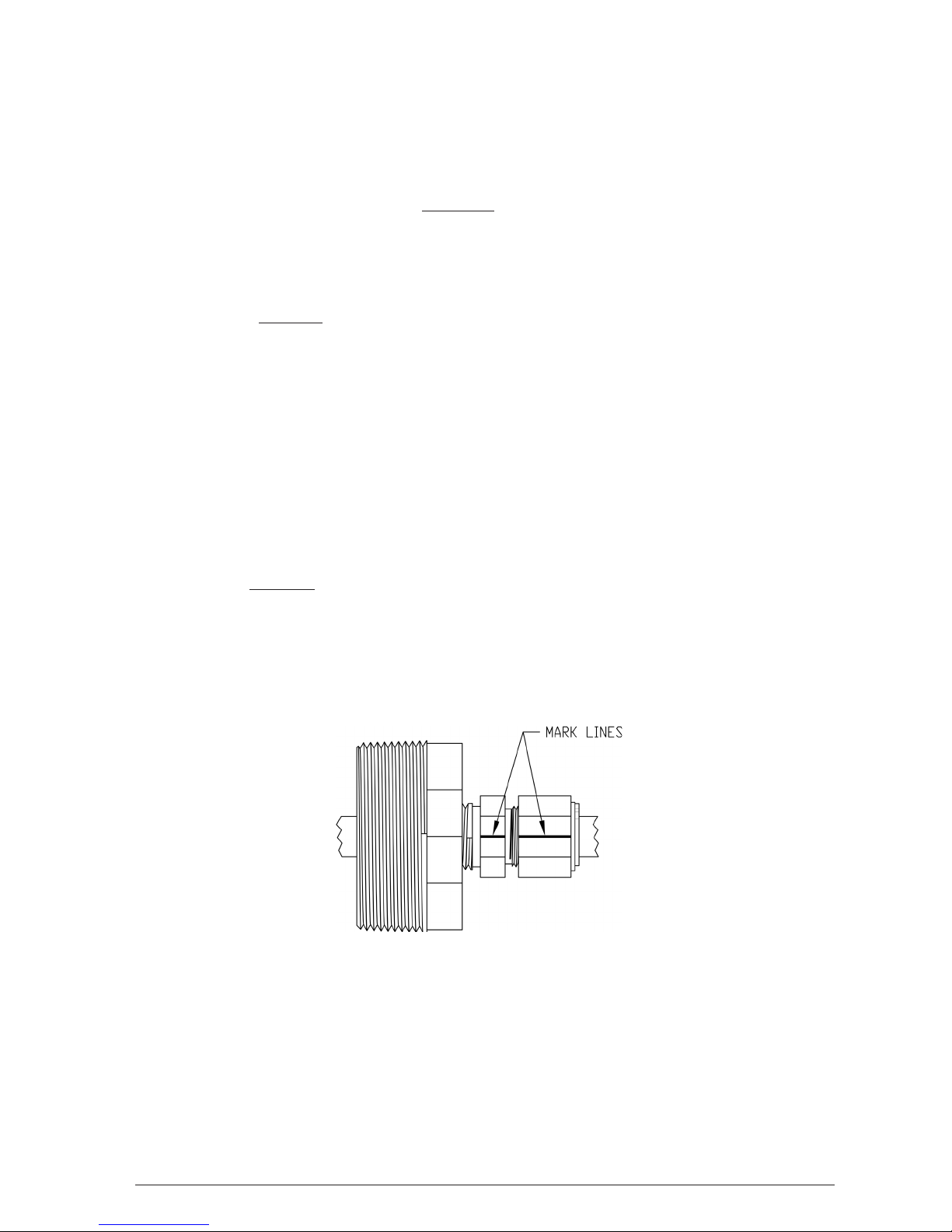
1. Mark the tting and the nut on the compression tting before loosening the nut, see example below.
2. Loosen nut enough so the tubing can slide up and down on the tting.
3. Slide tubing up or down to obtain your desired oat height adjustment.
NOTE: You cannot slide the tube up more than the gap between bottom of bushing and top retaining ring of the
highest oat.
4. Retighten the nut by hand.
5. Rotate the nut with a wrench to the original positon as indicated by previous marks lining up.
6. Double check your oat height, repeat steps 3 thru 5 if needed.
8-13-18
Morrison Bros. Co. ‑ Dubuque, IA ‑ 800‑553‑4840
925S‑‑0115 PP
2
 Loading...