

Page 1
POWER SPRAYER
Model: S151 and S201
Operator’s Manual
BARTELL MORRISON INC. BARTELL MORRISON (USA) LLC
375 ANNAGEM BLVD, MISSISSAUGA, ONTARIO, CANADA, L5T 3A7, 905-364-4200 FAX 905-364-4201
200 COMMERCE DRIVE, FREEHOLD, NEW JERSEY, USA, 07728, 732-566-5400 FAX 732-5444
Doc. # OI – M09205
Orig. Rel. – 07/2008
Curr. Rev. – 04
Rev. Date – 06/2014
Page 2

A
A
A
A
y
Revision Rev. Date
0
1
2
3
4
07-15-2008 Initial document release
08-17-2009 Relocation
12-21-2010 Layout
02-19-2013 Update to add S151 Sprayer
06-10-2014
Bartell Morrison Inc.
375 Annagem Blvd.
Mississauga, Ontario, Canada
L5T 3A7
Toll Free (N.A.): (866) 501-1683
Phone: (905) 364-4200
Facsimile: (905) 364-4201
ORIGINAL LANGUAGE OPERATING INSTRUCTIONS FOR
MORRISON POWER SPRAYERS © 2008 BY
BARTELL MORRISON INC.
ALL RIGHTS RESERVED.
No part of this work may be reproduced or transmitted in an
form or by any means, electronic or mechanical, including
photocopying and recording, or by any information storage or
retrieval system without the prior written permission of Bartell
Morrison Inc. unless such copying is permitted by federal
copyright laws.
Address inquiries or reference permissions ca re of:
Bartell Morrison Inc., 375 Annagem Blvd., Mississauga,
Ontario, Canada, L5T 3A7
Details
ddress Update
pproved
.L.
D.M.
R.L.
.L.
M.L.
BARTELL MORRISON INC. BARTELL MORRISON (USA) LLC
375 ANNAGEM BLVD, MISSISSAUGA, ONTARIO, CANADA, L5T 3A7, 905-364-4200 FAX 905-364-4201
200 COMMERCE DRIVE, FREEHOLD, NEW JERSEY, USA, 07728, 732-566-5400 FAX 732-566-5444
Created: 07/04
Revised: 06/14
Page 3

Table of Contents
1.0 Introduction …………………………………..…………... Page 4-6
1.1 Morrison Power Sprayer…...…………………… Page 4
1.2 Options………………………….………………… Page 4
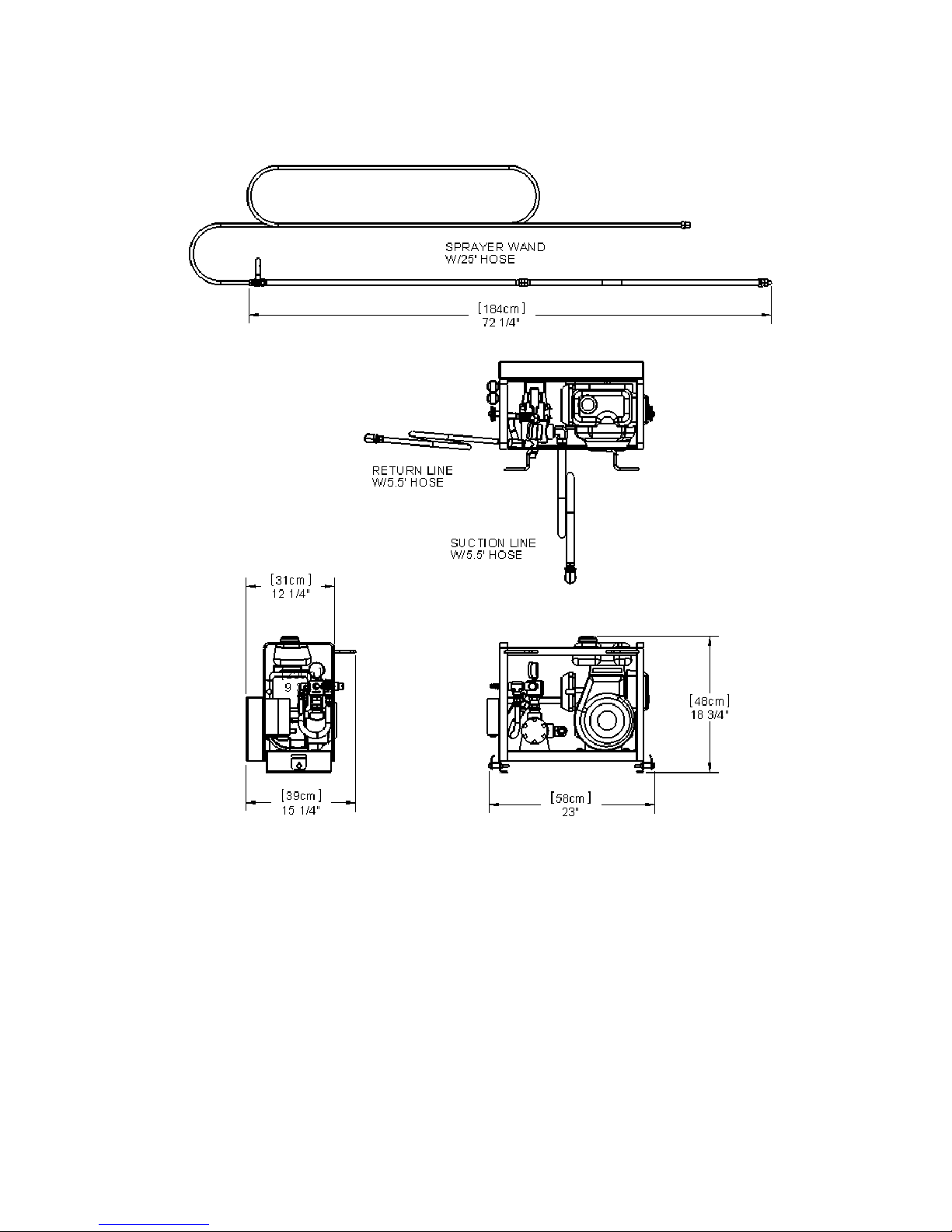
1.3 Dimensions………………………...……...……… Page 5
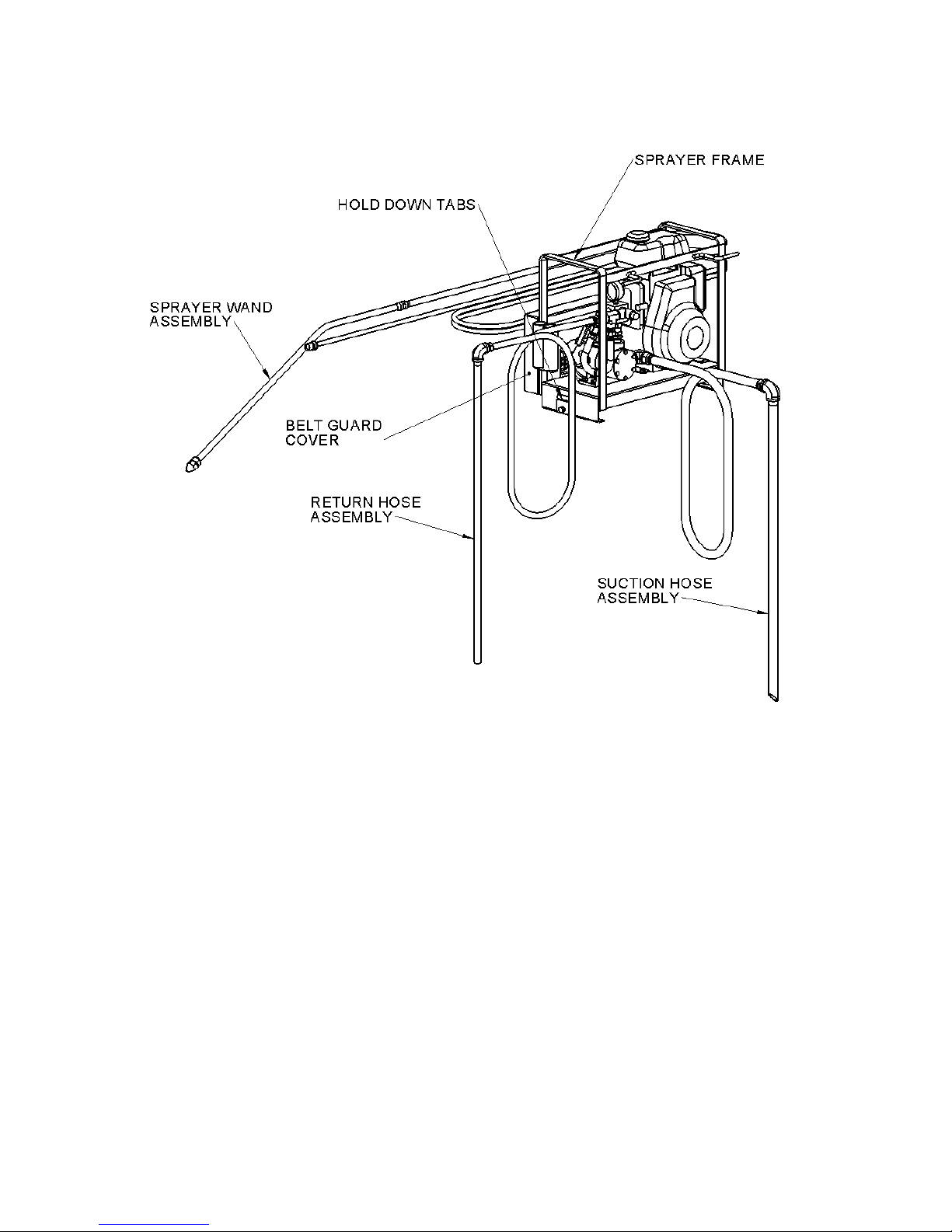
1.4 Sprayer Main Components……………………… Page 6
2.0 Safety Instructions…………………...…………………... Page 7-9
2.1 Read Operating Instruction……………………… Page 7
2.2 Product Safety Hazard and Alert System……… Page 7
2.3 Fueling Warning…………………………..……… Page 8
2.4 Safety Rules………………………….…………… Page 8
3.0 Safety and Operational Labels…………………………. Page 10
4.0 Sprayer Assembly………………………………………... Page 12
5.0 Sprayer Operating Instructions…………………………. Page 13-15
6.0 Pump Pressure Adjustment…………………………….. Page 15
7.0 Operating Tips and Reminders…………………………. Page 15
8.0 Maintenance……………………………………………… Page 16
8.1 Sprayer……………………………………………. Page 16
8.2 Engine…………………………………………….. Page 16
9.0 Warranty………………………..…………………………. Page 17
Declaration of Conformity………………………………………. Page 18
Notes……………………………………………………………… Page 20
Important Information:
Date of Purchase:
Dealer:
Model Number:
Serial Number:
BARTELL MORRISON INC. BARTELL MORRISON (USA) LLC
375 ANNAGEM BLVD, MISSISSAUGA, ONTARIO, CANADA, L5T 3A7, 905-364-4200 FAX 905-364-4201
200 COMMERCE DRIVE, FREEHOLD, NEW JERSEY, USA, 07728, 732-566-5400 FAX 732-566-5444
Created: 07/04
Revised: 06/14
Page 4

1.0 INTRODUCTION
TO THE OPERATOR:
DO NOT OPERATE THE BARTELL MORRISON POWER SPRAYER UNLESS
YOU HAVE READ AND STUDIED THIS MANUAL CAREFULLY.
REMEMBER THAT YOU ARE THE KEY TO SAFETY. GOOD SAFETY
PRACTICES NOT ONLY PROTECT YOU, BUT ALSO THOSE WORKING
AROUND YOU. MAKE THIS MANUAL A WORKING PART OF YOUR SAFETY
PROGRAM.
For safe operation of the power sprayer, you must be a qualified and authorized
operator. To be qualified, you must understand these written instructions, have
training, including actual operation of the power sprayer and know the safety rules
and regulations for your particular job site.
An operator should never use drugs, alcohol or any other substance which can
change his/ her alertness or coordination.
This manual is complied from information available and current at time of approval for
printing. Bartell Morrison Inc. reserves the right to improve its products without giving
prior notice or incurring any obligation
1.1 MORRISON POWER SPRAYER
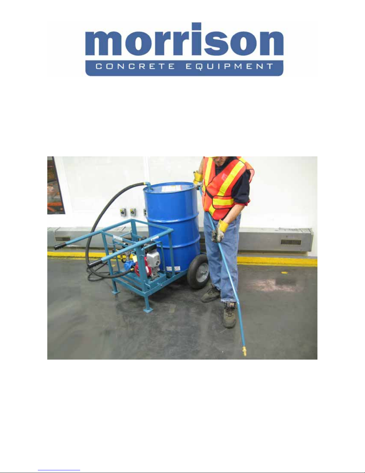
The Morrison Power Sprayer is ideal for spraying all types of curing compound on
bridge decks, highways, floor slabs, drainage channels, etc, after finishing work is
completed. Easily handles form oils, pigmented curing compounds, bond
breakers, soaps and detergents, pest control liquids, and most liquid type
material.
It is powered by a dependable Honda engine and comes with 25’ (7.6m) of 3/8”
(0.95cm) hose with an adjustable spray nozzle.
1.2 OPTIONS
Hose Lengths: 50’ (15.2m), 75’ (22.7m), 100’ (30.5m)
Fan Spray Nozzle
Hand Cart
Tow Cart
BARTELL MORRISON INC. BARTELL MORRISON (USA) LLC
375 ANNAGEM BLVD, MISSISSAUGA, ONTARIO, CANADA, L5T 3A7, 905-364-4200 FAX 905-364-4201
200 COMMERCE DRIVE, FREEHOLD, NEW JERSEY, USA, 07728, 732-566-5400 FAX 732-566-5444
Created: 07/04
Revised: 06/14
Page 5
1.3 Dimensions
BARTELL MORRISON INC. BARTELL MORRISON (USA) LLC
375 ANNAGEM BLVD, MISSISSAUGA, ONTARIO, CANADA, L5T 3A7, 905-364-4200 FAX 905-364-4201
200 COMMERCE DRIVE, FREEHOLD, NEW JERSEY, USA, 07728, 732-566-5400 FAX 732-566-5444
Fig. 1
Created: 07/04
Revised: 06/14
Page 6
1.4 Sprayer Main Components
Fig. 2
BARTELL MORRISON INC. BARTELL MORRISON (USA) LLC
375 ANNAGEM BLVD, MISSISSAUGA, ONTARIO, CANADA, L5T 3A7, 905-364-4200 FAX 905-364-4201
200 COMMERCE DRIVE, FREEHOLD, NEW JERSEY, USA, 07728, 732-566-5400 FAX 732-566-5444
Created: 07/04
Revised: 06/14
Page 7
2.0 SAFETY INSTRUCTIONS
2.1 READ OPERATING INSTRUCTIONS
Read and understand this entire manual before attempting to operate or
service the equipment described herein. Failure to follow these operating
instructions could result in serious injury or death. Store this manual with
the machine and ensure it is apparent and available to any users.
CALIFORNIA PROPOSITION 65 WARNING
Engine exhaust, some of its constituents, and certain vehicle
components, contain or emit chemicals known to the State of
California to cause cancer and birth defects or other reproductive
harm.
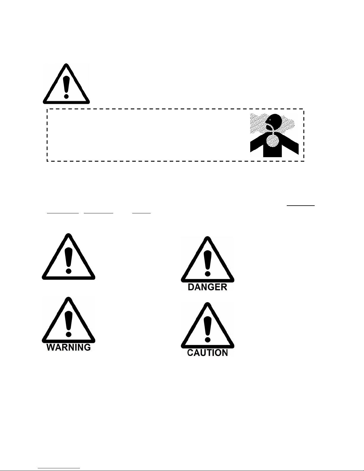
2.2 PRODUCT SAFETY AND HAZARD ALERT SYSTEM:
This Operating Manual presents Product Safety and Hazard Alert Information in accordance
with American National Standards Institute and International Organization for Standardization
recommendations as laid out in ANSI Z535 and ISO 3864. The callouts of DANGER,
WARNING, CAUTION, and NOTE must be followed to reduce or avoid the potential for
personal injury, equipment damage, or service-related equipment failures.
Safety Hazard Alert:
Alerts the reader to
personal injury hazards
and other important,
potentially life-saving
information.
WARNING:
Beware of a hazardous
situation that COULD
result in serious personal
injury or even death.
DANGER:
Beware of a hazardous
situation that WILL result in
serious personal injury or
untimely death.
CAUTION:
Beware of a hazardous
situation that could result in
minor personal injury or
equipment damage.
BARTELL MORRISON INC. BARTELL MORRISON (USA) LLC
375 ANNAGEM BLVD, MISSISSAUGA, ONTARIO, CANADA, L5T 3A7, 905-364-4200 FAX 905-364-4201
200 COMMERCE DRIVE, FREEHOLD, NEW JERSEY, USA, 07728, 732-566-5400 FAX 732-566-5444
Created: 07/04
Revised: 06/14
Page 8
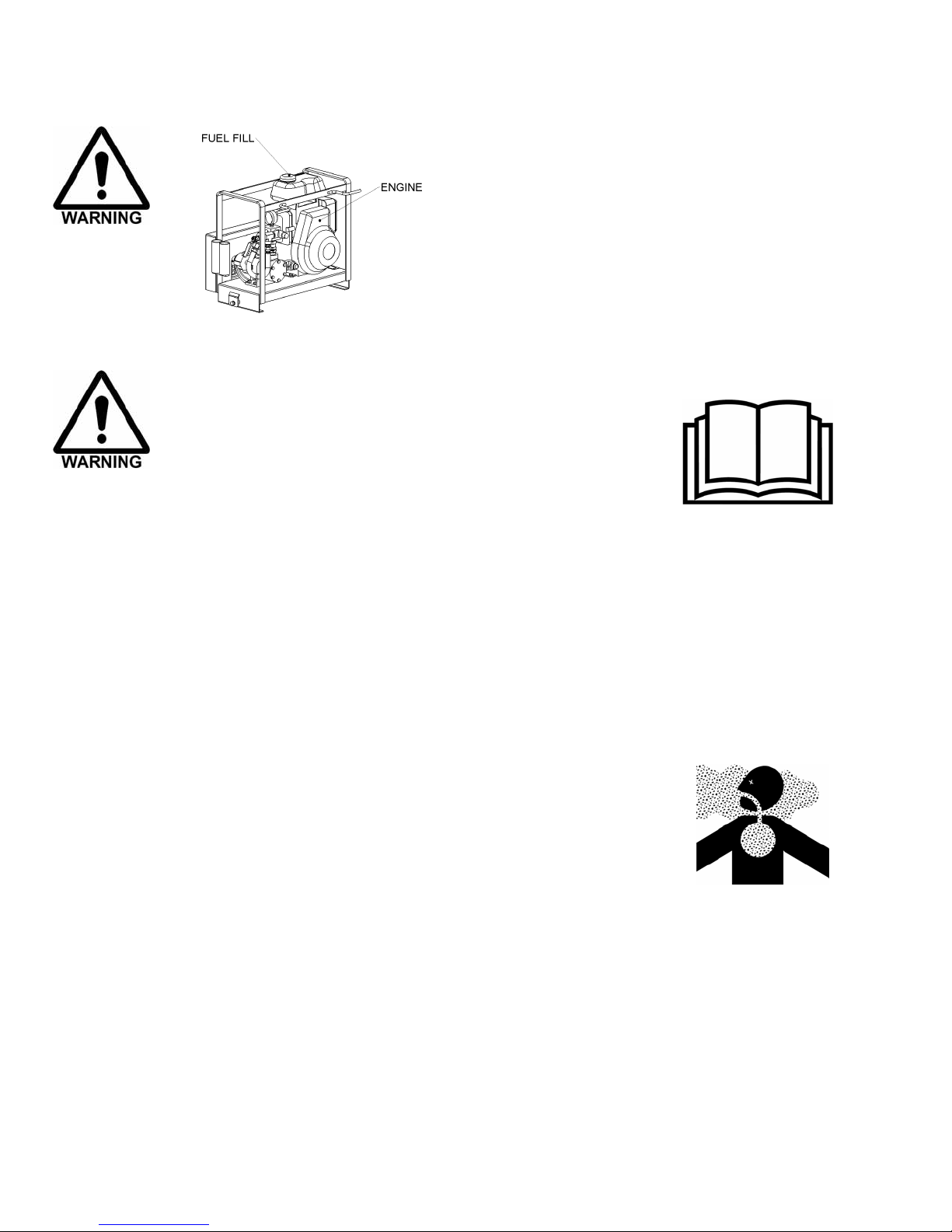
2.3 FUELING WARNING
ALWAYS handle fuel with care. It is highly
flammable.
DO NOT refuel while smoking or when near
open flame or sparks.
ALWAYS stop engine before refueling. Fill
Fig. 3
fuel tank outdoors.
2.4 SAFETY RULES
The instructions provided in this manual are done so to
ensure the operator’s safety as well as that of other
workers, the equipment, and the job site. Failure to abide
by these guidelines can lead to serious personal injury and
even death. The operator and any service personnel
should read and understand the entire manual before
working with or servicing the power sprayer.
The operator’s manual should be kept at all times in a place that is accessible
to any persons working with the machine. Replacement manuals can be
purchased from the equipment manufacturer or from your local dealer.
Only use parts and attachments supplied or approved by your Bartell Morrison
equipment dealer. The consequences of modifying the design of this
equipment can include personal injury, equipment failure, and voiding your
warranty. If you are unsure about a repair or an apparent malfunction, contact
your Bartell Morrison dealer or the technical support line at the bottom of each
page of this manual.
NEVER use the power sprayer in an enclosed space with
poor air flow, such as a basement or small room. The
gasoline engine produces, among other things, toxic carbon
monoxide gas. Without proper ventilation, this gas will build
up and cause health effects such as organ damage and
death to anyone in the vicinity.
The operator should always be lucid and aware of his/her surroundings.
NEVER operate the power sprayer while under the influence of drugs, alcohol,
fatigue, sickness, hangover, extreme depression, anti-depressants, or
emotional distraction.
ALWAYS wear appropriate personal protective equipment while operating the
Power Sprayer. This includes (but is not limited to) safety glasses, hearing
protection, protective footwear, and heavy or padded gloves. Other safety gear
may be job-site appropriate.
BARTELL MORRISON INC. BARTELL MORRISON (USA) LLC
375 ANNAGEM BLVD, MISSISSAUGA, ONTARIO, CANADA, L5T 3A7, 905-364-4200 FAX 905-364-4201
200 COMMERCE DRIVE, FREEHOLD, NEW JERSEY, USA, 07728, 732-566-5400 FAX 732-566-5444
Created: 07/04
Revised: 06/14
Page 9
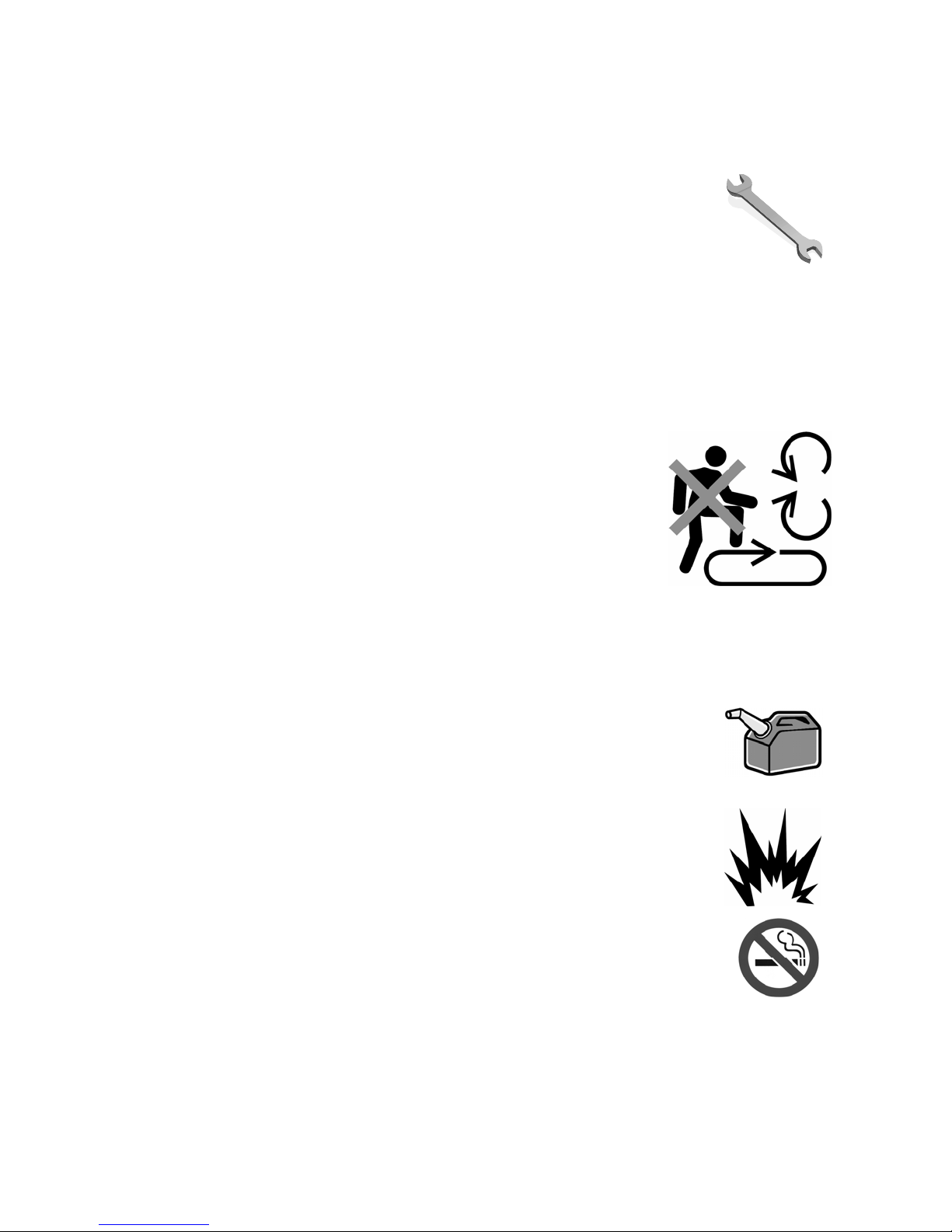
NEVER leave the power sprayer unattended while running.
Children and small animals should NEVER be present in the work area during
operation of the power sprayer.
ALWAYS check your power sprayer for loose or missing nuts
and bolts before starting. Tighten any loose fasteners and replace
missing or broken parts.
Perform all routine maintenance as described within this manual. Failure to do
so will void your warranty and will eventually result in premature equipment
failure.
NEVER perform maintenance on a running piece of equipment. Shut down the
engine and allow it to cool before servicing the power sprayer, including
mechanical work or lubrication.
ALWAYS replace missing, damaged or unclear safety
labels to ensure operator awareness and safety.
NEVER operate the power sprayer with missing or
damaged safety guards. Replace immediately with
appropriate Morrison parts.
NEVER put hands, feet, or other appendages inside the
belt guard while the engine is running, even at idle or
with protective clothing, as serious injury may result.
NEVER wear loose fitting clothing or jewelry around rotating equipment such
as the power sprayer as it may become entangled in the machinery, resulting
in serious injury.
ALWAYS refuel the power sprayer in a well-ventilated area,
away from ignition sources such as sparks, flames, and lit
cigarettes. Smoking while fuelling the equipment may result in
explosion.
Ensure the engine has cooled sufficiently before refueling to
avoid igniting gasoline fumes.
NEVER operate the power sprayer in explosive environments
such as paint fumes, methane, natural gas, fine particulate,
aerosol propellant, or solvent fumes.
NEVER smoke near the power sprayer as stray gasoline fumes
may ignite. Operating the power sprayer around an open flame
may also result in explosion.
ALWAYS shut down the engine and allow it to cool off before lifting or
transporting the power sprayer.
ALWAYS tie down the power sprayer when being transported in a truck or on
a flatbed. Empty the fuel tank if transporting it over long distances.
BARTELL MORRISON INC. BARTELL MORRISON (USA) LLC
375 ANNAGEM BLVD, MISSISSAUGA, ONTARIO, CANADA, L5T 3A7, 905-364-4200 FAX 905-364-4201
200 COMMERCE DRIVE, FREEHOLD, NEW JERSEY, USA, 07728, 732-566-5400 FAX 732-566-5444
Created: 07/04
Revised: 06/14
Page 10
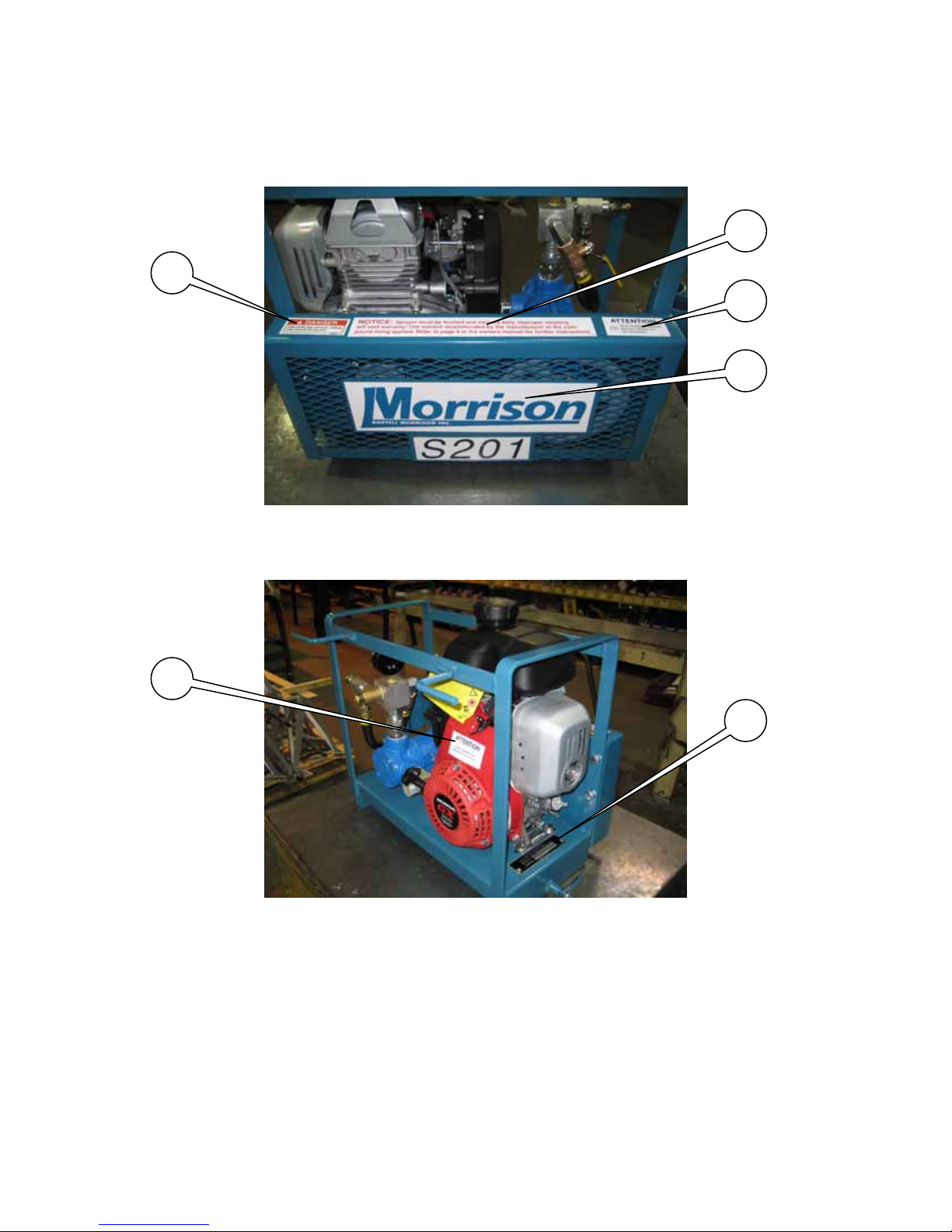
3.0 SAFETY AND OPERATIONAL LABELS
3
6
4
1
6
2
BARTELL MORRISON INC. BARTELL MORRISON (USA) LLC
375 ANNAGEM BLVD, MISSISSAUGA, ONTARIO, CANADA, L5T 3A7, 905-364-4200 FAX 905-364-4201
200 COMMERCE DRIVE, FREEHOLD, NEW JERSEY, USA, 07728, 732-566-5400 FAX 732-566-5444
Created: 07/04
Revised: 06/14
Page 11
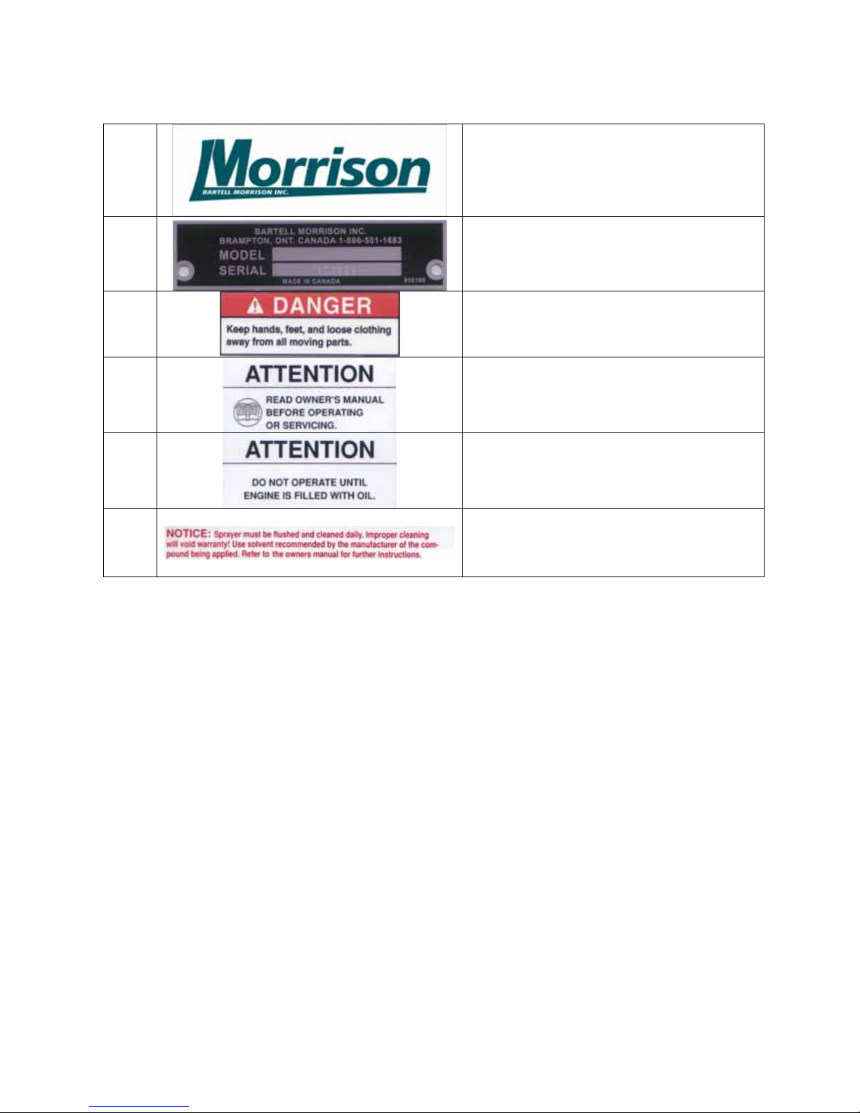
1 Product Brand Label
2
3
4
5
6
Model and Serial Number plate
DANGER: Keep hands, feet, and
loose clothing away from all moving
parts.
ATTENTION: Read and understand
owner’s manual before operating or
servicing this equipment.
ATTENTION: Do not operate this
equipment until the engine is checked
and filled with oil.
NOTICE: Sprayer must be flushed
and cleaned daily. Refer to page 16
for instructions.
BARTELL MORRISON INC. BARTELL MORRISON (USA) LLC
375 ANNAGEM BLVD, MISSISSAUGA, ONTARIO, CANADA, L5T 3A7, 905-364-4200 FAX 905-364-4201
200 COMMERCE DRIVE, FREEHOLD, NEW JERSEY, USA, 07728, 732-566-5400 FAX 732-566-5444
Created: 07/04
Revised: 06/14
Page 12
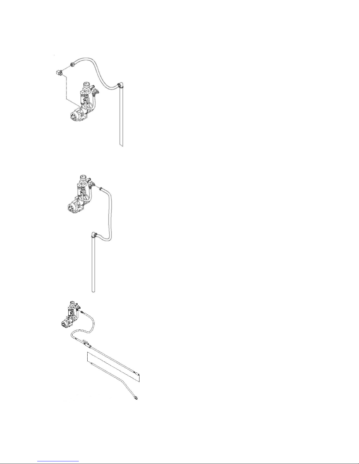
4.0 SPRAYER ASSEMBLY
Fig. 4 - Suction Hose
Connection
Fig. 5 - Return
Hose Connection
Your new Power Sprayer will arrive with everything you
need in one shipping carton. Be sure to examine the
content to be certain that the following items were
included:
Return Hose: ½” hose/pipe
Suction Hose: ¾” hose/pipe
Sprayer Wand Assembly: 25 ft. of 3/8” hose and (2)
3/8” pipes with a coupler
1. Remove the sprayer from the carton and place it on
the curing drum you will be using. The sprayer
should be mounted so that the openings on the drum
are accessible on either side of the sprayer. Tighten
the hold down tabs on the sprayer to the drum.
2. Attach the suction hose/pipe to the sprayer using the
fitting mounted directly to the pump. (See Fig. 4)
3. Attach the fitting end of the return hose/pipe to the
sprayer using the ½” connection on the spray block
assembly. (See Fig. 5)
4. Join the two section of the sprayer wand together
using the pipe coupling provided. (See Fig. 6)
5. Attach the spray hose to the last fitting on the
sprayer block assembly. (See Fig. 6)
You are now ready to begin operation of the sprayer.
Fig. 6 - Spray Hose &
Wand Connection
BARTELL MORRISON INC. BARTELL MORRISON (USA) LLC
375 ANNAGEM BLVD, MISSISSAUGA, ONTARIO, CANADA, L5T 3A7, 905-364-4200 FAX 905-364-4201
200 COMMERCE DRIVE, FREEHOLD, NEW JERSEY, USA, 07728, 732-566-5400 FAX 732-566-5444
Created: 07/04
Revised: 06/14
Page 13
5.0 SPRAYER OPERATING INSTRUCTIONS
Before starting engine, refer to the engine owner’s manual, follow the engine
manufacturer’s instructions for proper starting procedures, and follow the steps
below.
CAUTION: If the material you are working with has solids in it, these will settle to
the bottom of the drum. You must agitate it thoroughly before
attempting to spray the material. If you do not do this, the sprayer will
become clogged and possibly damage the pump.
1. Insert the suction hose into the drum using the larger of the two access holes. We
recommend using a support under the hose so that it will not reach the bottom of
the drum where sediment can clog the suction hose.
2. Insert the return hose into the drum using the smaller of the two openings.
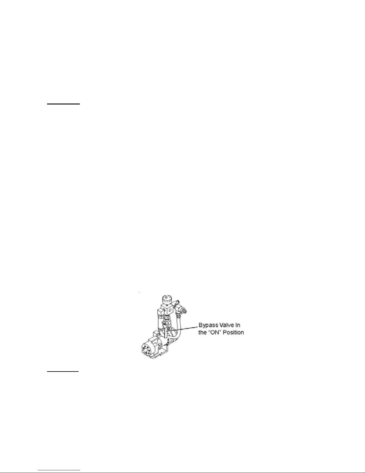
3. The sprayer has a bypass valve that allows the engine to be started without
pressure building in the pump. Turn out counter-clockwise the pressure relief to
lowest setting and rotate the bypass valve handle to the downward position
before starting the engine. This valve allows you to stir the curing material by
circulating it directly through the pump.
4. Read the engine manufacturer’s instructions carefully before starting the engine.
CHECK OIL!!
5. Check the end of the suction hose to be certain it is immersed in the liquid but not
in the sediment in the bottom of the drum.
6. With the bypass valve in the on, downward position, start the engine and allow it
to run for 2-10 minutes. This aids in the mixing of the spray compound and
assures greater pump efficiency and life. (See Fig. 6)
Fig. 6
NOTICE: Some compounds have a tendency to foam when air is introduced.
This foaming can cause erratic pump performance. Please do not insert spray
nozzle into the drum in n attempt to stir the material! This will only cause more
foam in the compound.
BARTELL MORRISON INC. BARTELL MORRISON (USA) LLC
375 ANNAGEM BLVD, MISSISSAUGA, ONTARIO, CANADA, L5T 3A7, 905-364-4200 FAX 905-364-4201
200 COMMERCE DRIVE, FREEHOLD, NEW JERSEY, USA, 07728, 732-566-5400 FAX 732-566-5444
Created: 07/04
Revised: 06/14
Page 14
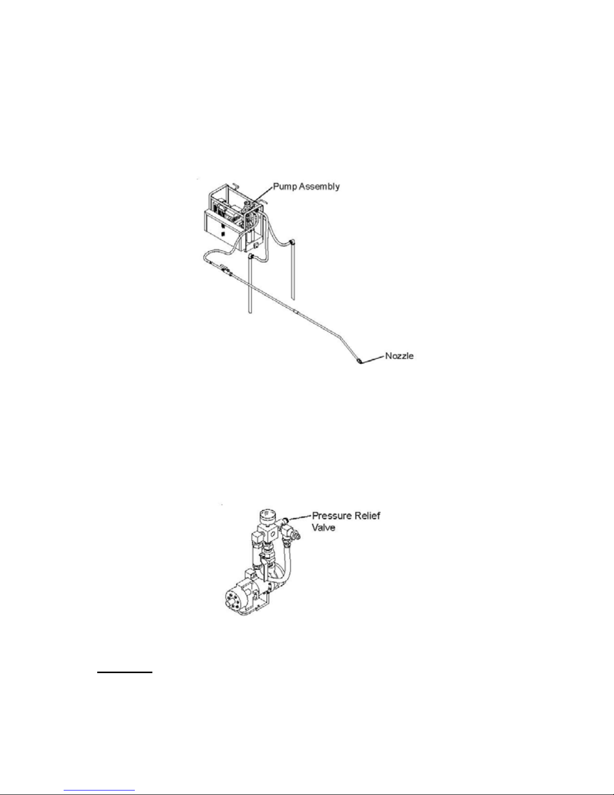
7. Be certain the spray wand is off before turning the bypass valve to the off position
to pressurize the system.
8. Turn the bypass valve to the off position. You are now ready to spray.
9. Adjustments to the spray pattern can be made with the nozzle at the end of the
spray wand. Turn the nozzle counterclockwise to narrow the spray pattern, and
clockwise to broaden the spray pattern.
Fig. 7
10. The sprayer has an adjustable pressure relief valve (See Fig. 8) on the block
assembly. You may need to vary the pressure according to the viscosity of the
material you are using. Thinner liquids tend to need more pressure to assure a
good coverage pattern. It is recommended to use a lower pressure setting for
certain liquids, especially with higher solids, as high pressures can be
problematic.
Fig. 8
CAUTION: NEVER EXCEED 100 PSI (S151) or 150 PSI (S201)
BARTELL MORRISON INC. BARTELL MORRISON (USA) LLC
375 ANNAGEM BLVD, MISSISSAUGA, ONTARIO, CANADA, L5T 3A7, 905-364-4200 FAX 905-364-4201
200 COMMERCE DRIVE, FREEHOLD, NEW JERSEY, USA, 07728, 732-566-5400 FAX 732-566-5444
Created: 07/04
Revised: 06/14
Page 15

11. While not spraying, turn the bypass valve on to remove unnecessary pressure
from the pump. Turning off the engine when not spraying will prolong the life of
the pump.
12. The return hose may be used to check for any sediment remaining lodged at the
bottom of the drum. If none is detected, the suction hose can be lowered
completely into the drum. If sediment remains after several minutes of spraying, it
may be necessary to remove the sprayer and stir the material manually.
6.0 PUMP PRESSURE ADJUSTMENT
Please refer to the instruction manual for the pump.
7.0 OPERATING TIPS AND REMINDERS
1. Always start the engine with the bypass valve in the on position to
reduce system pressure and the pressure relief set to low.
2. Always stir the compound before attempting to operate the sprayer.
3. When not spraying, turn the bypass valve to the on position, or stop
the engine. This will add several hours of life to your sprayer.
4. Follow manufacturer’s directions and safety procedures in the use of
materials used to clean the sprayer.
5. Periodically clean the spray nozzle, as materials tend to clog, causing
poor spray performance.
6. Clean the sprayer after every use.
7. Flush after cleaning completely so that no solvents remain in the
system.
8. Use care to avoid crimping or damaging hoses. Do not allow
accumulations of compounds to build up on hoses.
9. NEVER directly spray nozzle in the direction of eyes or face.
BARTELL MORRISON INC. BARTELL MORRISON (USA) LLC
375 ANNAGEM BLVD, MISSISSAUGA, ONTARIO, CANADA, L5T 3A7, 905-364-4200 FAX 905-364-4201
200 COMMERCE DRIVE, FREEHOLD, NEW JERSEY, USA, 07728, 732-566-5400 FAX 732-566-5444
Created: 07/04
Revised: 06/14
Page 16

8.0 MAINTENANCE
It is essential that the sprayer be cleaned on a daily basis. Parts that fail due to
improper cleaning will not be warranted. Use the following steps as a guide to proper
cleaning and maintenance.
8.1 Sprayer
1. Place the suction hose into a container that has been filled with a solvent
recommended by the compound manufacturer to clean spraying equipment
after use.
2. Place the return hose in an empty container the same size, or larger than the
one with the cleaning agent.
3. Turn the bypass valve to the on position and start the engine. Allow the
cleaning agent to run through the pump for 2-3 minutes.
4. Turn the bypass valve to the off position and spray wand to the on position.
Allow the want to spray into the empty container for about 20 seconds. This
procedure may need to be repeated several times to insure that the pump and
spray wand are clean.
5. Check the procedures for cleaning provided by the solvent manufacturer.
Some cleaning solvents require that they be flushed out with water after they
are used. If this is the case, we recommend that a small amount of form oil or
diesel fuel be used AFTER using water. This will prevent the internal
components of the pump from seizing, due to the formation of rust on the
pump internals.
6. Disconnect all the hoses and allow all the liquid to drain from the lines.
7. As you begin your next spraying operation, spray a small amount of compound
through the lines and into an empty container. This will clear any remaining
water or solvent before it is mixed with the regular spraying compound.
8.2 Engine
Refer to engine owner’s manual for specific information regarding maintenance.
Check the oil level in your engine prior to start up and then every 10 hours of
operation. Maintain the proper levels at all times.
Drain oil after every 50 hours or operation and refill with grade of oil as
recommended in the engine owner’s manual.
Above 40 Deg. F (13 Deg. C)- S. A. E. 30
Below 40 Deg. F (13 Deg. C)- S. A. E. 20
Cold Weather Note:
In climates where temperatures are below 35 Deg. F, hard starting may occur. In
these cases the oil should be switched to a thinner 15 weight hydraulic fluid.
BARTELL MORRISON INC. BARTELL MORRISON (USA) LLC
375 ANNAGEM BLVD, MISSISSAUGA, ONTARIO, CANADA, L5T 3A7, 905-364-4200 FAX 905-364-4201
200 COMMERCE DRIVE, FREEHOLD, NEW JERSEY, USA, 07728, 732-566-5400 FAX 732-566-5444
Created: 07/04
Revised: 06/14
Page 17

9.0 Warranty
All products sold by Bartell Morrison Inc. and Bartell Morrison (USA) LLC (the “Company”)
are warranted against defects in materials and/or workmanship; excluding normal wear on
wearing components and components covered by a separate original manufacturers
warranty, for a period of 12 months from the date of sale to the original end user
purchaser provided that certain conditions have been met.
Conditions:
1. The equipment serial number has been registered with the Company or its approved
dealers, distributors, representatives or agents.
2. The equipment has been operated in an appropriate manner by qualified individuals.
3. The equipment has been properly maintained as per the instructions included in the
Owner’s Manual.
4. All claims for warranty must be filed on proper forms and include the serial number of the
equipment along with proof of purchase.
Any evidence of failure to meet these conditions may result in a denial of the warranty claim.
Consideration of warranty claims will be at the sole discretion of the Company, or its
authorized dealers, distributors, representatives or agents.
The Company may, at its discretion, request that the equipment to be considered for
warranty be returned at the owner’s expense to an authorized repair facility for
inspection.
Under this warranty we may, at our discretion, repair or replace a part or the whole of the
defective component or equipment.
Our Warranty coverage is limited to the cost to repair or replace the defective portion of
the equipment and a reasonable (as determined by the Company) amount of labour to
conduct the repair or replacement.
Under no circumstances shall the Company be liable for any additional or exceptional
costs beyond the cost to repair or replace the defective portion of the equipment. The
Company shall not be held accountable for; costs associated with travel to inspect or
repair defective equipment, costs for transporting defective equipment to or from an
authorized repair facility, costs incurred to repair or replace the defective equipment at
any facility other than one authorized by the Company or ancillary damage caused by or
as a result of the defective equipment.
Under no circumstances shall equipment be returned to the Company or its authorized
dealers, distributors, representatives or agents without the approval of the Company as
evidenced by a Returned Goods Number. To obtain a Returned Goods Number contact
the factory or your authorized dealer, distributor, representative or agent.
This warranty is for the sole benefit of the original end user purchaser and is not
transferable to any other company or person.
BARTELL MORRISON INC. BARTELL MORRISON (USA) LLC
375 ANNAGEM BLVD, MISSISSAUGA, ONTARIO, CANADA, L5T 3A7, 905-364-4200 FAX 905-364-4201
200 COMMERCE DRIVE, FREEHOLD, NEW JERSEY, USA, 07728, 732-566-5400 FAX 732-566-5444
Created: 07/04
Revised: 06/14
Page 18

Declaration of Conformity / Certificat de conformité / Gelijkvormigheids certificaat
Declaración de Conformidad/Declaração de Conformidade/Dichiarazione Di Conformita
We: Bartell Morrison Inc.
375 Annagem Blvd.
Mississauga, Ontario, Canada
L5T 3A7
Tel: 905-364-4200 Fax: 905-364-4201
Declare under our sole responsibility that the product to which this declaration relates is in
conformity with the following standard(s) or other normative documents.
Déclarons sous notre responsabilité que le produit cette déclaration est conforme aux
normes suivantes ou d’autres documents habituels.
Verklaren onder onze verantwoordelijkheid dat het product naar welke de verklaring verwijst
conform de volgende standaards of anders gebruikelijke documenten is.
Declaramos bajo nuestra única responsabilidad que el producto en lo que esta declaración
concierne, es conforme con la siguiente normativa u otros documentos.
Declara sob sua responsabilidade que o produto a quem esta declaração interessar, está
em comformidade com os seguintes documentos legais ou normas directivas.
Dichiariamo sotto la ns. unica responsibilita che il prodotto al quale questa dichiarazione si
riferisce, è fabbricato in conformità ai seguenti standard e documenti di normative.
EN 349:1993
EN 418:1993
EN 12100-1:2003
EN 12100-2:2003
EN ISO 4872:1978
EN ISO 5349-
1:2001
EN ISO 5349-
2:2001
Following the provisions of Directive(s):
Suivant les directive(s) déterminées:
Volgens de vastgestelde richtlijnen:
Siguiendo las directiva(s):
No sequimento das clausulas da Directiva(s):
Seguendo quanto indicato dalla Direttiva(s):
98/37/EC Machinery Directive
2000/14/EC Noise Directive
2001/95/EC General Product Safety Directive
2002/95/EC Reduction of Hazardous Waste Directive
Safety of Machinery - Minimum gaps to avoid crushing of parts of the
human body.
Safety of Machinery - Emergency stop equipment, functional aspects
- Principles for design
Safety of Machinery - Basic Concepts, general principles for design Part 1: Basic Terminology, methodology
Safety of Machinery - Basic Concepts, general principles for design Part 2: Technical Principles
Acoustics - Measurement of Airborne noise emitted by construction
equipment intended for outdoor use - Method for determining
compliance with noise limits.
Mechanical vibration. Measurement and evaluation of human
exposure to hand-transmitted vibration. General requirements
Mechanical vibration. Measurement and assessment of human
exposure to hand-transmitted vibration. Practical guidance for
measurement at the workplace.
BARTELL MORRISON INC. BARTELL MORRISON (USA) LLC
375 ANNAGEM BLVD, MISSISSAUGA, ONTARIO, CANADA, L5T 3A7, 905-364-4200 FAX 905-364-4201
200 COMMERCE DRIVE, FREEHOLD, NEW JERSEY, USA, 07728, 732-566-5400 FAX 732-566-5444
Created: 07/04
Revised: 06/14
Page 19
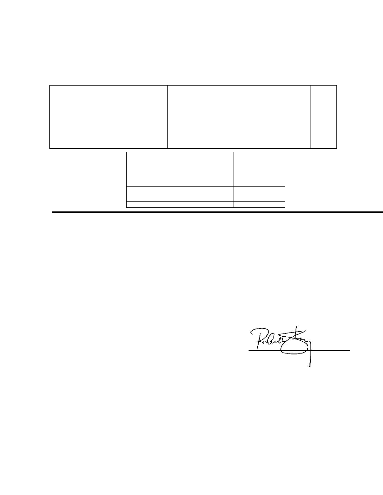
Technical Characteristics:
A
g
Caractéristiques techniques:
Technisch gegevens:
Características Técnicas:
Caracteristicas Técnicas:
Qualitàs di tecnico:
Model
Modéle
Type
Modelo
Modelo
Modello
Lbs
MORRISON POWER SPRAYER 95
The Technical Construction file is maintained at:
Les fiches techniques de construction sont gardées à:
Noise Level
Puissance acoustique
Geluidniveau
Nivel Sonoro
Nivel del Ruido
Potenza Acustica
Lwa
(dB)
98 99 1.5
MachineSerial Number
Numéro de Série machine
Serienummer machine
Máquina número de série
Numero de serie da maquina
Numero di seria la macchina
Het technische constructie document wordt bewaard te:
El archivo técnico de construcción se mantiene en:
O arquivo técnico de construção é mantido no (a):
L’originale dossier tecnico di construzione è conservato presso:
The authorized representative is:
Le représentant autorisé est:
Gemachtigd vertegenwoordiger is:
La representación autorizada es:
O representante autorizado é:
Il rappresentate autorizzato:
Signature of Authorized Person:
Signature de la personne autorisée:
Handtekening van gemachtigd persoon:
Firma de la persona autorizada:
ssinatura de pessoa autorizada:
Firma della persona autorizzata:
Typed name of Authorized Person:
Nom dactlyographié de la personne autorisée:
Getypte naam van gemachtigd persoon:
Nombre de la persona autorizada:
Nome datilografado da pessoa autorizada:
Nome della persona autorizzata:
Title of Authorized Person:
Titre de la personne autorisée:
Functie van gemachtigd persoon:
Cargo de la persona autorizada:
Titulo da pessoa autorizada:
Posizione della persona autorizzata:
Date and place of issue:
Date et place d’émission:
Datum en plaats van afgifte:
Fecha y lugar de emision:
Data e lugar de emissão:
Data e luo
o di emissione:
375 ANNAGEM BLVD, MISSISSAUGA, ONTARIO, CANADA, L5T 3A7, 905-364-4200 FAX 905-364-4201
BARTELL MORRISON INC. BARTELL MORRISON (USA) LLC
200 COMMERCE DRIVE, FREEHOLD, NEW JERSEY, USA, 07728, 732-566-5400 FAX 732-566-5444
Pressure level
Pression acoustique
Geluidsdrukniveau
Nivel Acustico
Pressão Acústica
Pressione Acustica
Lpa
(Db)
Engine Serial Number
Numéro de Série moteur
Serienummer motor
Motor número de série
Numero de serie do motor
Numero di seria la motore
Vibration level
Niveau de vibration
Vibratieniveau
Nivel de Vibracion
Nivel de Vibração
Livello di Vibrazione
a
hv
(m/s2)
Bartell Morrison Inc.
375 Annagem Blvd.
Mississauga, Ontario, Canada
L5T 3A7
Telephone: 905-364-4200
Facsimile: 905-364-4201
Mr. Steve Adam
International Sales Manager
c.o. Bartell Morrison Europe
Nijverheidsstraat 11
1840 Londerzeel
Belgium
Telephone: +1 514 463 4838
Facsimile: +1 514 697 4239
Richard Stanley
V.P. of Operations
11.05-2012
Mississauga, Ontario, Canada
Created: 07/04
Revised: 06/14
Weight
Masse
Gewicht
Masa
Massa
Massa
(kg)
(43)
Page 20

NOTES
BARTELL MORRISON INC. BARTELL MORRISON (USA) LLC
375 ANNAGEM BLVD, MISSISSAUGA, ONTARIO, CANADA, L5T 3A7, 905-364-4200 FAX 905-364-4201
200 COMMERCE DRIVE, FREEHOLD, NEW JERSEY, USA, 07728, 732-566-5400 FAX 732-566-5444
Created: 07/04
Revised: 06/14
 Loading...