

Page 1

SW-UNM-5FE
SOHO 5 Fast Ethernet Ports
--Ver: 1.0
User’s Manual
Page 2
1 Package Contents
Check the contents of your package for following parts:
Fast Ethernet Switch x 1
User's Manual x 1
Power Adapter (5V 0.5A) x 1
If any of these are missing or damaged, please contact your dealer immediately, if
possible, retain the carton including the original packing material, and use them against to
repack the product in case there is a need to return it to us for repair.
2. Product Features
Complies with IEEE 802.3, IEEE 802.3u, IEEE802.3x、IEEE802.3az standards
5 fast Ethernet Auto-Negotiation RJ45 po
Supports IEEE802.3x flow control for Full-duplex Mode and backpressure for
Half-duplex Mode
Store and forward mode operates
Supports MAC address auto-learning and auto-aging
Supports IEEE802.3az Protocol
rts supporting Auto-MDI/MDIX
3. Switch Front Panel
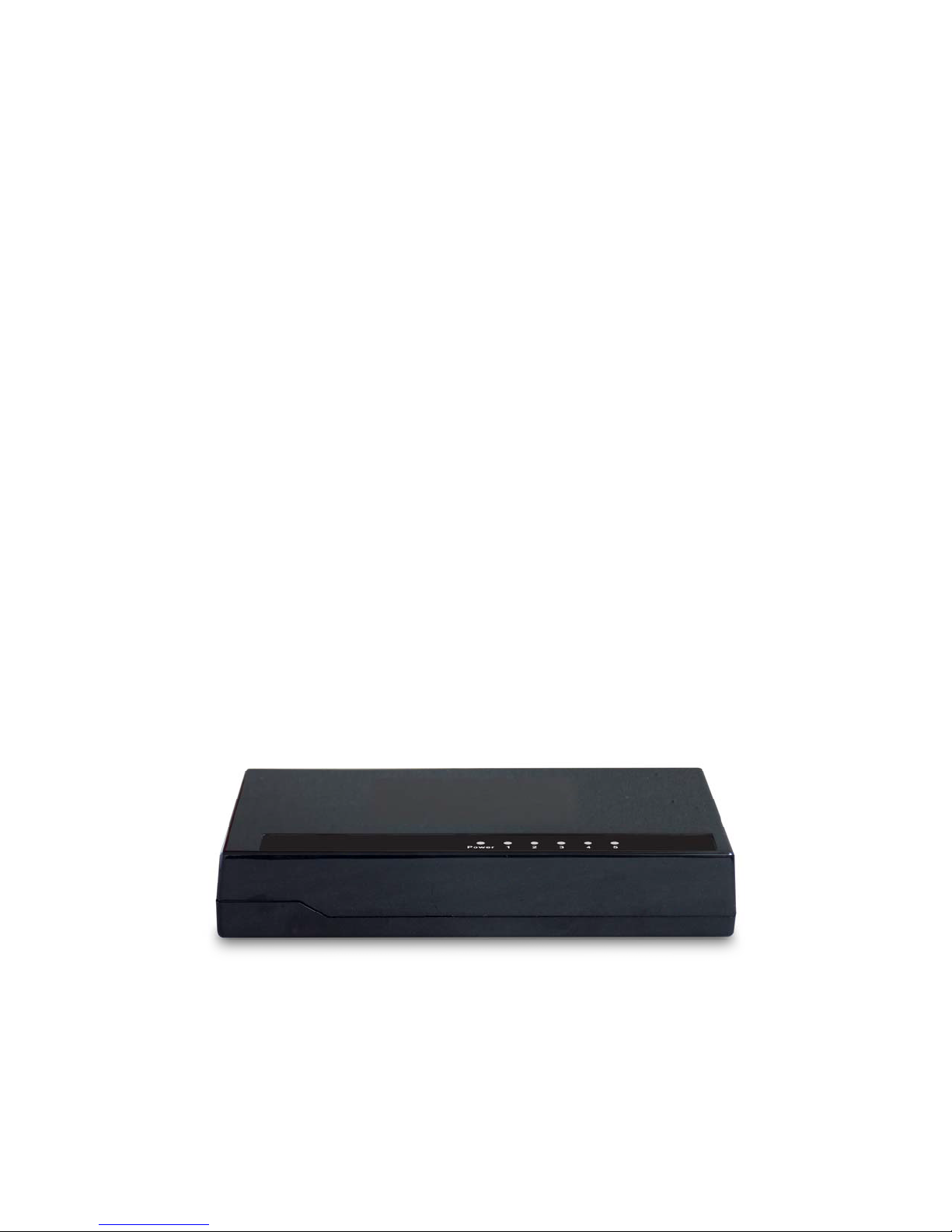
Figure 1-1 shows a front panel of the switch.
Figure 1-1 switch front panel
4 LED Indicators
- 1 -
Page 3
LED Function
PWR Lit: Power on.
Lit: indicate the link through that port is successfully
LINK/ACT
established.
Blink: indicate that the Switch is actively sending or
receiving data over that port.
5. Switch Rear Panel
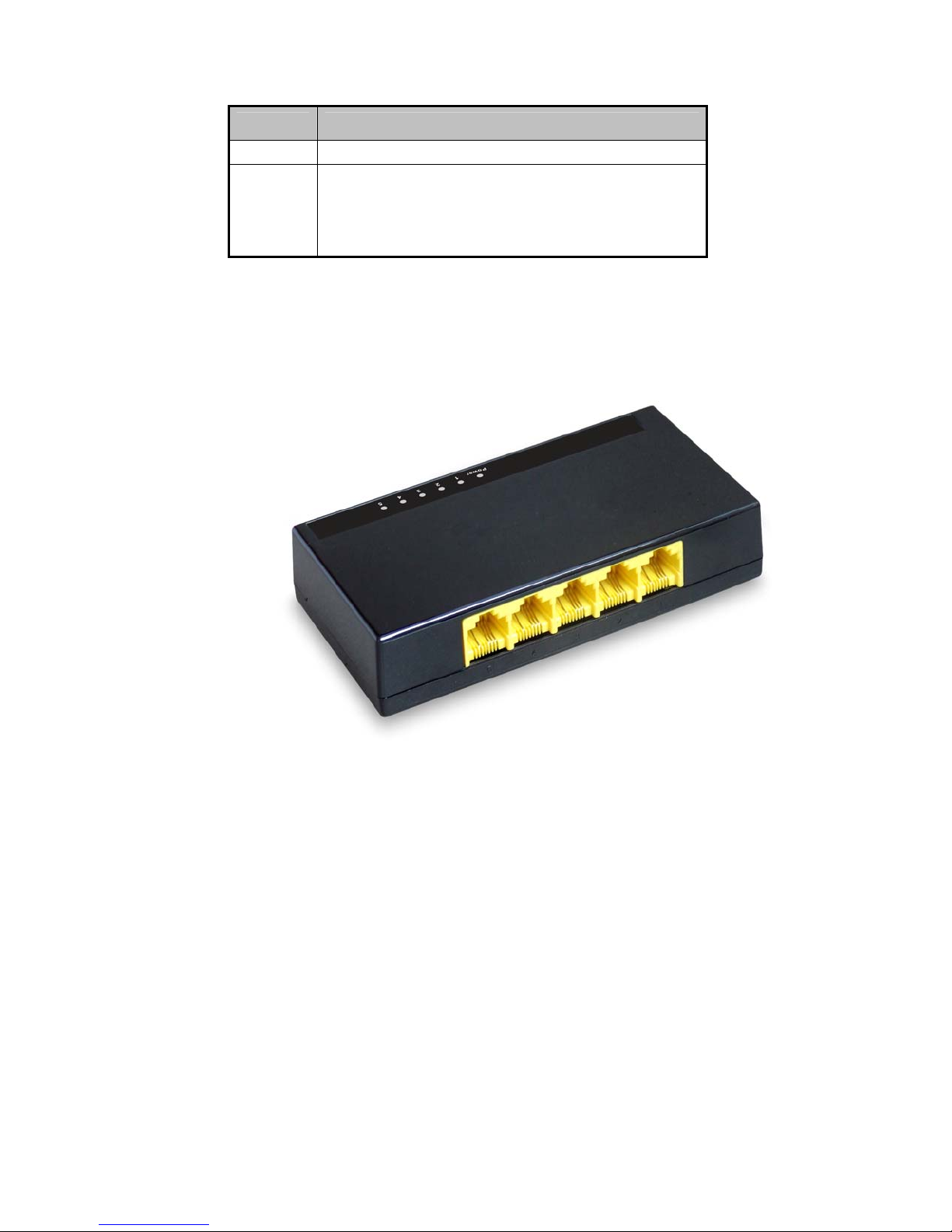
Figure 1-2 shows a rear panel of the switch.
Ports
These ports are connection points for PCs and other network devices, such as additional
switches.
Power
The power port is where you will connect the external power adapter. (The power port of
the switch on the side way)
6. Installing the Switch
This part describes how to install your Fast Ethernet Switch and make connections to it.
Please read the following topics and perform the procedures in the order being presented.
Desktop Installation
Figure 1-2 switch rear panel
- 2 -
Page 4

To install the Switch on desktop, simply follow the next steps:
Step 1: Place the Switch on desktop near an AC power source.
Step 2: Keep enough ventilation space between the Switch and the surrounding objects.
Step 3: Connect your Switch to network devices.
A. Connect one end of a standard network cable to the 10/100 RJ-45 ports on the Back of
the Switch.
B. Connect the other end of the cable to the network devices such as printer servers,
workstations or routers…etc.
Step 4: Supply power to the Switch.
A. Connect one end of the power cable to the Switch.
B. Connect the power adapter to a standard wall outlet.
When the Switch receives power, the Power LED should remain solid Green.
- 3 -
Page 5

 Loading...