

Morrell SW-MNG-8GE2GSFP-8POE User Manual
SW-MNG-8GE2GSFP-8POE
8-Port 10/100/1000Mbps + 2-Port Gigabit SFP
Managed POE Ethernet Switch
User Manual
Version 1.3 | 6/6/2016

Table of Contents
Chapter 1 Product Introduction ................................................................... 4
1.1 Product Overview ............................................................................... 4
1.2 Features .............................................................................................. 4
1.3 External Component Description ........................................................ 4
1.3.1 Front Panel .............................................................................................. 4
1.3.2 Rear Panel .............................................................................................. 6
1.4 Package Contents............................................................................... 6
Chapter 2 Installing and Connecting the Switch ....................................... 8
2.1 Installation ........................................................................................... 8
2.1.1 Desktop Installation ................................................................................. 8
2.1.2 Rack-mountable Installation in 11-inch Cabinet ....................................... 8
2.1.3 Power on the Switch ................................................................................ 9
2.2 Connect Computer (NIC) to the Switch .............................................. 9
2.3 Switch connection to the PD ............................................................... 9
Chapter 3 How to Login the Switch ........................................................... 10
3.1 Switch to End Node .......................................................................... 10
3.2 How to Login the Switch ................................................................... 10
Chapter 4 Switch Configuration ................................................................ 13
4.1 Quickly set ........................................................................................ 13
4.2 PORT ................................................................................................ 15
4.2.1 Basic config ........................................................................................... 16
4.2.2 Port Aggregation ................................................................................... 17
4.2.3 Port mirroring ........................................................................................ 18
4.2.4 Port rate-limit ......................................................................................... 19
4.2.5 Storm control ......................................................................................... 20
4.2.6 Port isolation ......................................................................................... 21
4.3 VLAN ................................................................................................. 22
4.3.1 VLAN config .......................................................................................... 22
4.3.2 Trunk-port setting .................................................................................. 24
4.3.3 Hybrid-port setting ................................................................................. 25
4.4 Fault/Safety ....................................................................................... 27
4.4.1 Anti Attack ............................................................................................. 27
4.4.1.1 Anti DHCP Attack ............................................................................................... 27
4.4.1.2 Anti DOS ............................................................................................................ 2 9
4.4.1.3 IPsource Guard .................................................................................................. 30
4.4.1.4 Anti Three Bind .................................................................................................. 31
4.4.2 Channel detection ................................................................................. 32
1

4.4.2.1 Ping testing ........................................................................................................ 3 2
4.4.2.2 Tracert testing .................................................................................................... 33
4.4.2.3 Cable testing ...................................................................................................... 34
4.4.3 ACL ....................................................................................................... 35
4.5 MSTP ................................................................................................ 36
4.5.1 MSTP Region ........................................................................................ 37
4.5.2 MSTP Bridge ......................................................................................... 38
4.6 DHCP RELAY ................................................................................... 40
4.6.1 DHCP Relay .......................................................................................... 40
4.6.2 0ption82 ................................................................................................ 41
4.7 QoS ................................................................................................... 43
4.7.1 Remark .................................................................................................. 43
4.7.2 Queue Config ........................................................................................ 44
4.7.3 Mapping the queue ................................................................................ 45
4.7.3.1 Service class queue mapping ............................................................................ 46
4.7.3.2 Differential service class mapping ..................................................................... 46
4.7.3.3 Port to service class mapping ............................................................................ 47
4.8 Address table .................................................................................... 49
4.8.1 Mac add and delete ............................................................................... 49
4.8.2 Mac study and aging ............................................................................. 51
4.8.3 Mac address filtering ............................................................................. 52
4.9 SNMP ................................................................................................ 53
4.9.1 Snmp config .......................................................................................... 53
4.9.1.1 Snmp config ....................................................................................................... 53
4.9.1.2 Community config .............................................................................................. 54
4.9.1.3 View Config ........................................................................................................ 54
4.9.1.4 Group Config ...................................................................................................... 55
4.9.1.5 User config ......................................................................................................... 5 7
4.9.1.6 Trap .................................................................................................................... 58
4.9.2 Rmon Config ......................................................................................... 59
4.9.2.1 Statistics Group .................................................................................................. 59
4.9.2.2 History Group ..................................................................................................... 60
4.9.2.3 Event Group ....................................................................................................... 61
4.9.2.4 Alarm Group ....................................................................................................... 62
4.10 SYSTEM ......................................................................................... 63
4.10.1 System Config ..................................................................................... 63
4.10.1.1 System settings ................................................................................................ 63
4.10.1.2 System restart .................................................................................................. 66
4.10.1.3 Password change ............................................................................................ 67
4.10.1.4 SSH login ......................................................................................................... 67
4.10.1.5 Telnet login ....................................................................................................... 6 8
4.10.1.6 System log ....................................................................................................... 69
4.10.2 System Upgrade.................................................................................. 70
4.10.3 Config Management ............................................................................ 70
2

4.10.3.1 Current configuration ....................................................................................... 71
4.10.3.2 Configuration backup ....................................................................................... 72
4.10.3.3 Restore factory configuration ........................................................................... 73
4.10.4 Config Save ......................................................................................... 74
4.10.5 Administrator Privileges ....................................................................... 75
4.10.6 Info Collect .......................................................................................... 75
Appendix: Technical Specifications ............................................................ 77
3

Chapter 1 Product Introduction
Congratulations on your purchase of the PoE Web Smart Ethernet Switch. Before you
install and use this product, please read this manual carefully for a full understanding of its
functions.
1.1 Product Overview
The 8-port + 2SFP 10/100/1000M PoE Web Smart Ethernet Switch provides seamless
network connection. It integrates 10/100/1000Mbps Ethernet network capabilities in a
highly flexible package. These PoE ports can automatically detect and supply power with
those IEEE 802.3at compliant Powered Devices (PDs). In this situation, the electrical
power is transmitted along with data in one single cable allowing you to expand your
network where there are no power lines or outlets, where you wish to fix devices such as
APs, IP Cameras and IP Phones, etc.
The Web Smart Ethernet Switch, and can be configured by web based interface. Including
administrator, port management, VLAN setting, each port statistics, trunking setting, QoS
setting, security filter, configuration/backup/recovery, log out, and so on.
1.2 Features
Complies with IEEE802.3i, IEEE802.3u, IEEE802.3ab, IEEE802.3x, IEEE802.3z.
IEEE802.1q, IEEE802.1p standards.
8x10/100/1000Mbps Auto-Negotiation RJ45 ports supporting Auto-MDI/MDIX.
Supports PoE power up to 30W for each PoE port.
Supports All power up to 140W.
Support the Console port management.
Supports PoE IEEE802.3at compliant PDs.
Supports IEEE802.3x flow control for the Full-duplex Mode and backpressure for the
Half-duplex Mode.
8K entry MAC address table of the Switch with auto-learning and auto-aging.
Supports WEB management interface.
LED indicators for monitoring power, link, activity and speed.
Internal power adapter supply.
1.3 External Component Description
1.3.1 Front Panel
The front panel of the Switch consists of 8 x 10/100/1000Mbps RJ-45 ports, 1 x Console
port, 2 x SFP ports, 1 x Reset button and a series of LED indicators as shown as below.
4
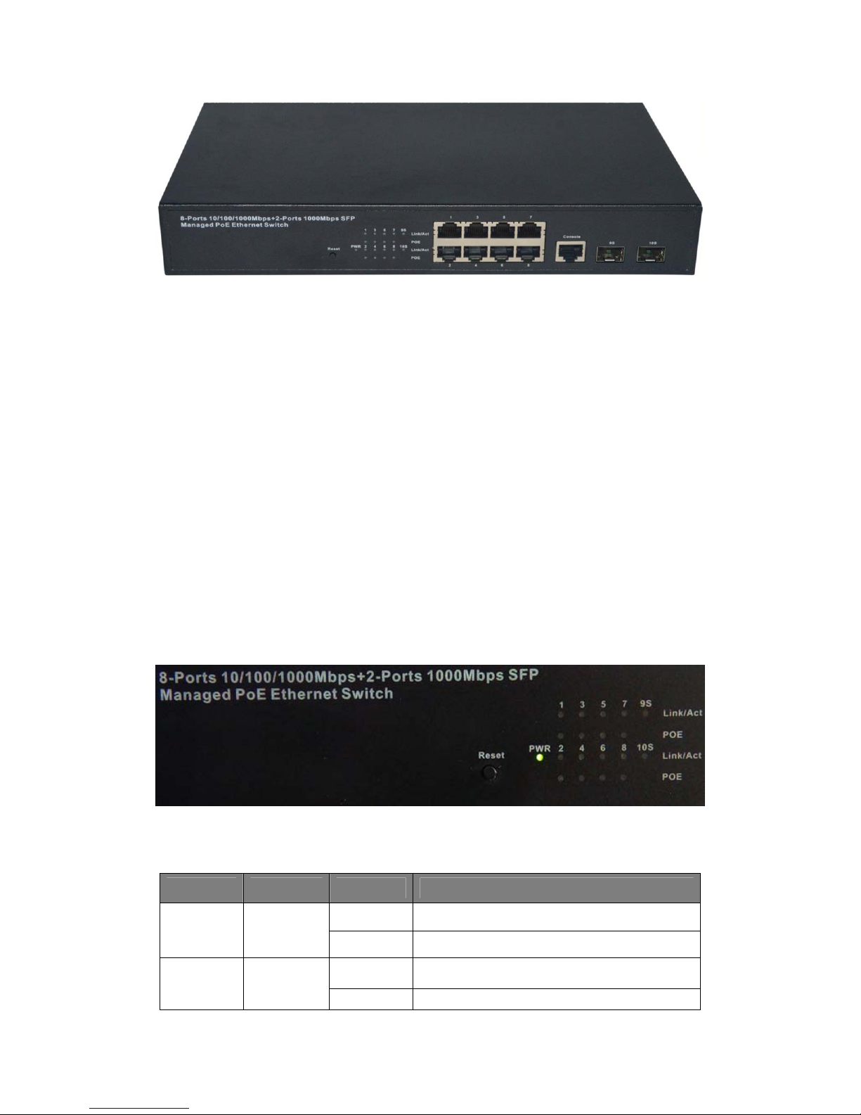
Figure 1 - Front Panel
10/100/1000Mbps RJ-45 ports (1~8):
Designed to connect to the device with a bandwidth of 10Mbps, 100Mbps or 1000Mbps.
Each port has a corresponding 10/100/1000Mbps LED.
Console port (Console):
Designed to connect with the serial port of a computer or a terminal for monitoring and
configuring the Switch.
SFP ports (SFP1, SFP2):
Designed to install the SFP module and connect to the device with a bandwidth of
1000Mbps. Each has a corresponding 1000Mbps LED.
Reset button (Reset):
To restore the system factory default settings, press the reset button for 5 secends while
the device is powered on.
LED indicators:
The LED Indicators will allow you to monitor, diagnose and troubleshoot any potential
problem with the Switch, connection or attached devices.
Figure 2 - LED Indicators
The following chart shows the LED indicators of the Switch along with explanation of each
indicator.
LED COLOR STATUS STATUS Description
On Power On
PWR Green
Off Power Off
Link/Act/
Speed
10/100M:
Orange
On A device is connected to the port
Off A device is disconnected to the port
5

(1-8)
PoE Yellow
Link/Act
(9S-10S)
1000M:
Green
Green
Flashing Sending or receiving data
On
Off
Flashing
On A device is connected to the port
Off A device is disconnected to the port
Flashing Sending or receiving data
A Powered Device is connected to the port,
which supply power successfully.
No PD is connected to the corresponding
port, or no power is supplied according to
the power limits of the port.
The PoE power circuit may be in short or
the power current may be overloaded.
1.3.2 Rear Panel
The rear panel of the Switch contains AC power connector and one marker shown as
below.
Figure 3 - Rear Panel
AC Power Connector:
Power is supplied through an external AC power adapter. It supports AC 100~240V,
50/60Hz.
Grounding Terminal:
Ground the Switch through the PE cable on the AC cord with a separate ground wire.
1.4 Package Contents
Before installing the Switch, make sure that the following items are enclosed. If any part is
lost and damaged, please contact your local agent immediately. In addition, make sure
that you have the tools install switches and cables by your hands.
One PoE Web Smart Ethernet Switch.
Four rubber feet, two mounting ears and eights screws.
6

One AC power cord.
One User Manual.
7

Chapter 2 Installing and Connecting the Switch
This chapter describes how to install your PoE Ethernet Switch and make connections to
it. Please read the following topics and operate the procedures in the order being
presented.
2.1 Installation
Please follow the following Instructions in avoid of incorrect installation causing device
damage and security threat.
Put the Switch on stable surface or desktop to minimize the chances of falling.
Make sure the Switch works in the proper AC input range and matches the voltage
labeled on the Switch.
To prevent electrocution, do not open the Switch’s chassis, even if it fails to receive
power.
Make sure that there is proper heat dissipation from and adequate ventilation around
the Switch.
Make sure the surface on which the Switch placed can support the weight of the
Switch and its accessories.
2.1.1 Desktop Installation
When installing the Switch on a desktop (if not in a rack), attach the enclose rubber feet
provided to the bottom corners of the Switch to minimize vibration. Allow adequate space
for ventilation between the device and the objects around it.
2.1.2 Rack-mountable Installation in 11-inch Cabinet
The Switch can be mounted in an EIA standard-sized, 11-inch rack, which can be placed
in a wiring closet with other equipment. To install the Switch, please follow these steps:
a. attach the mounting brackets on the Switch’s side panels (one on each side) and
secure them with the screws provided.
Figure 4 - Bracket Installation
b. use the screws provided with the equipment rack to mount the Switch on the rack and
tighten it.
8

Figure 5 - Rack Installation
2.1.3 Power on the Switch
The Switch is powered on by connecting it to an outlet using the AC 100-240V 50/60Hz
internal high-performance power supply. Please follow the next tips to connect:
AC Electrical Outlet:
It is recommended to use single-phase three-wire receptacle with neutral outlet or
multifunctional computer professional receptacle. Please make sure to connect the metal
ground connector to the grounding source on the outlet.
AC Power Cord Connection:
Connect the AC power connector on the back panel of the Switch to an external
receptacle with the included power cord, and check the power indicator is ON or not.
When it is ON, the corresponding LED is illuminated.
2.2 Connect Computer (NIC) to the Switch
Please insert the NIC into the computer, after installing network card driver, please
connect one end of the twisted pair to RJ-45 jack of your computer, the other end will be
connected to any RJ-45 port of the Switch, the distance between Switch and computer is
around 100 meters. Once the connection is, succeed and the devices are power on
normally, the LINK/ACT/Speed LEDs for each port will be illuminated.
2.3 Switch connection to the PD
The 1-8 ports of the Switch have PoE power supply function, the maximum output power
of each port is 30W. The switch can supply power to the PD devices, such as internet
phone, network camera, wireless access point work, by linking the device with the Switch
using network cable.
9
Chapter 3 How to Login the Switch
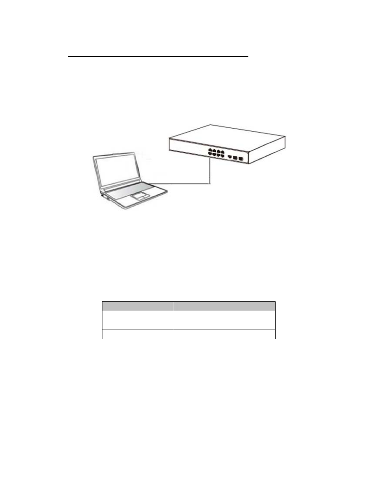
3.1 Switch to End Node
Use standard Cat.5/5e Ethernet cable (UTP/STP) to connect the Switch to end nodes as
described below. Switch ports will automatically adjust to the characteristics (MDI/MDI-X,
speed, duplex) of the device to which is connected.
Figure 6 - PC Connect
Please refer to the LED Indicators. The Link/Act/Speed LEDs for each port illuminated
when the link is available.
3.2 How to Login the Switch
As the Switch provides Web-based management login, you can configure your computer’s
IP address manually to log on to the Switch. The default settings of the Switch are shown
below.
Parameter Default Value
Default IP address 192.168.2.1
Default user name admin
Default password admin
1. You can log on to the configuration window of the Switch through the following steps:
2. Connect the Switch with the computer NIC interface.
3. Power on the Switch.
4. Check whether the IP address of the computer is within this network segment:
192.168.2.xxx (“xxx” ranges 2~254), for example, 192.168.2.100.
5. Open the browser, and enter http://192.168.2.1 and then press “Enter”. The Switch
login window appears, as shown below.
10
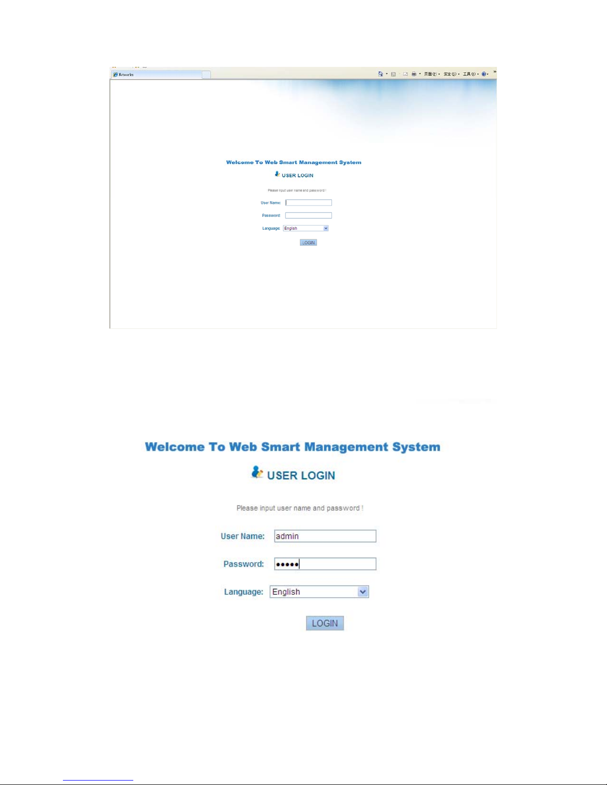
Figure 7- Login Windows
6. Switching language to English. Enter the Username and Password (The factory
default Username is admin and Password is admin), and then click “LOGIN” to log in
to the Switch configuration window as below.
11
12
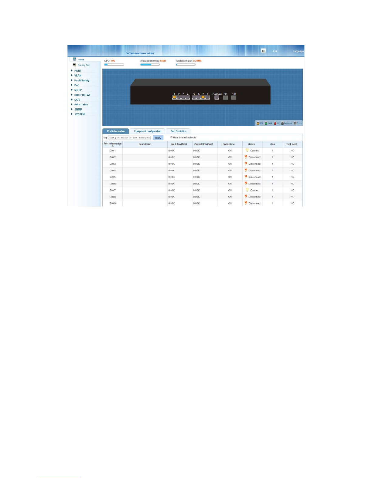
Chapter 4 Switch Configuration
The Web Smart Ethernet Switch Managed switch software provides rich layer two
functionality for switches in your networks. This chapter describes how to use Web-based
management interface (Web UI) to this Switch configure managed switch software
features. In the Web UI, the left column shows the configuration menu. You can find the
information for switch system, such as memory, software version on the top of the page.
The middle shows the Switch’s current link status. Green squares indicate the port link is
up, while black squares indicate the port link is down. Below the switch panel, you can find
a common toolbar to provide useful functions for users. The rest of the screen area
displays the configuration settings.
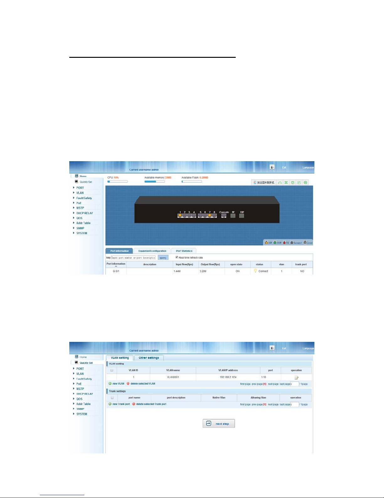
4.1 Quickly set
Select “Quickly Set” in the navigation bar, you can create a VLAN, add the port in the
VLAN, set the basic information and modify the Switch login password. The following
picture:
13
【Parameter Description】
Parameter Description
VLAN ID VLAN number, 8GE default VLAN 1
VLAN name VLAN mark
Manage IP Manage the IP address of the VLAN
device name Switch name
Manage VLAN Switches management in use of the VLAN
【Instructions】
Native VLAN: as a Trunk, this port must belong to a Native VLAN. The so-called Native
VLAN, refers to UNTAG send/receive a message on the interface, is considered belongs
to the VLAN. Obviously, the interface of the default VLAN ID (PVID) in the IEEE 802.1 Q
VLAN ID is the Native VLAN. At the same time, send belong to Native VLAN frame on the
Trunk, must adopt UNTAG way.
Allowed VLAN list: a Trunk can transport the equipment support by default all the VLAN
traffic (1-4094). But also can by setting the permission VLAN Trunk at the mouth of the list
to limit the flow of some VLAN cannot through the Trunk.
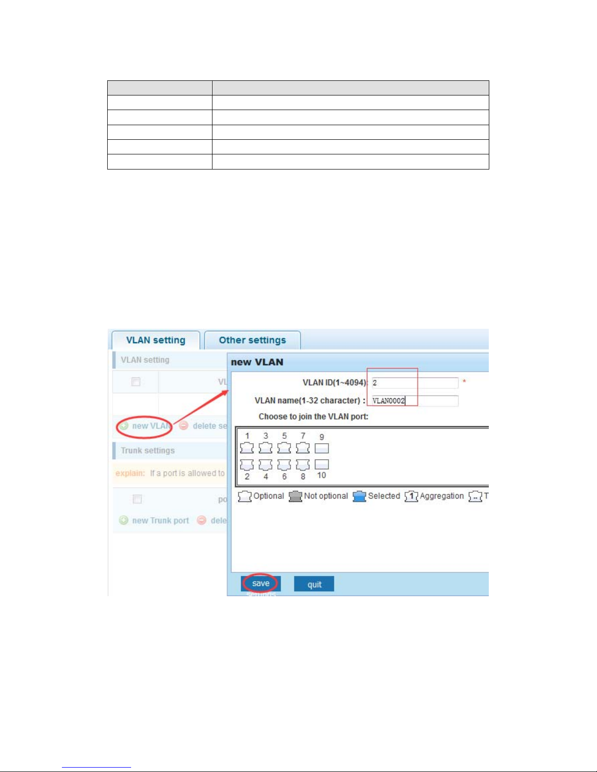
【Configuration example】
1) VLAN setting: Such as create VLAN 2, Sets the port 8 to Trunk, Native VLAN 2.
14
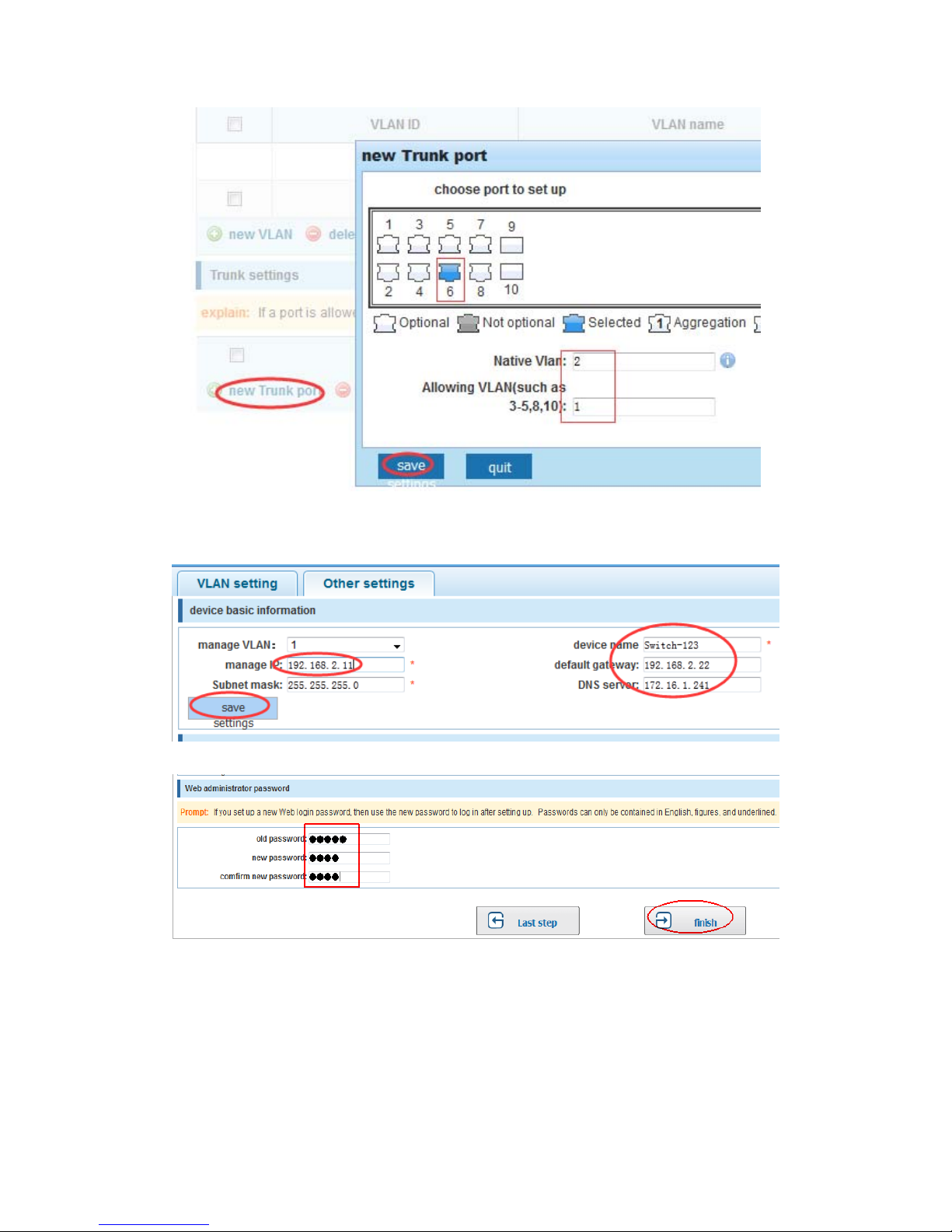
2) Click “next step” button, into other settings, such as manage ip address set as
192.168.2.11, device name set as switch-123, default gateway with the dns server
set as 172.16.1.241.
3) Use 192.168.2.11 to log in, set a new password for 1234.
4.2 PORT
Selecting “PORT” in the navigation bar, you may conduct Basic Config, Port
Aggregation, Port Mirroring, Port Limit and Port Isolation.
15
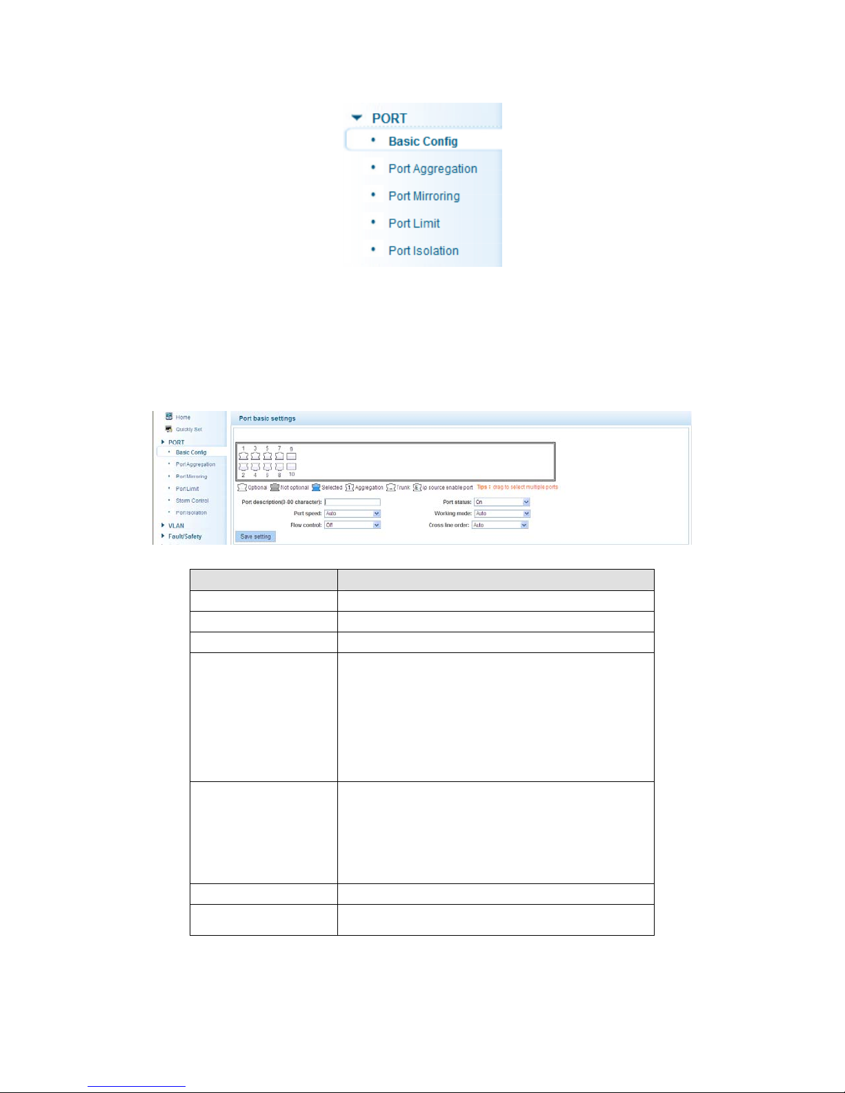
4.2.1 Basic config
Selecting “PORT>Basic Config” in the navigation bar, you can configure Port description,
Port speed, Port status, Working mode, Flow control, Cross line order configuration, the
following picture:
【Parameter Description】
Parameter Description
port Select the current configuration port number
port status Choose whether to close link port
flow control Whether open flow control
Can choose the following kinds:
Aggregation
port speed
10 M
100 M
1000 M
Can choose the following kinds:
Self negotiated
working mode
10 M
100 M
1000 M
port described The port is described
Cross line sequence Whether open intersection line sequence
【Instructions】
Open to traffic control will be auto negotiation closed, auto-negotiation is to set the port
speed and working mode; the port rate set more than the actual rate of port, port will drop.
16
【Configuration example】
For example: Setting the Port speed as ‘10M’, Working mode as ‘Duplex’, Flow control as
‘On’, Cross line sequence and Port status as ‘On’.
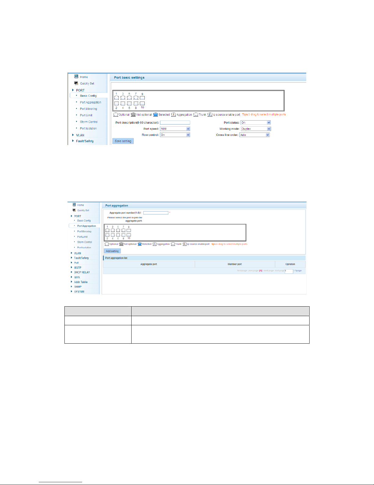
4.2.2 Port Aggregation
In the navigation bar to select “PORT>Port Aggregation”. In order to expand the port
bandwidth or achieve the bandwidth of the redundancy backup, the following picture:
【Parameter Description】
Parameter Description
Aggregation port 8GE Switch can be set up 8 link trunk group, group_1 to group_8
Member port
For each of the members of the group and add your own port,
and with members of other groups
【Instructions】
Open the port of the ARP check function, the port of the important device ARP, the port of
the VLAN MAC function, and the monitor port in the port image cannot be added.
【Configuration example】
Such as: set the port as ’7, 8’, for aggregation port 1, lets this aggregation port 1
connected to other switch aggregation port 1 to build switch links .
17
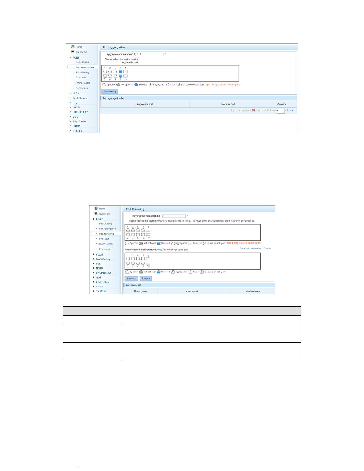
4.2.3 Port mirroring
In the navigation bar to select “PORT>Port Mirroring”, Open port mirror feature, All the
packets on the source port are copied and forwarded to the destination port, destination
port is usually connected to a packet analyzer to analyze the source port, multiple ports
can be mirrored to a destination port, the following picture:
【Parameter Description】
Parameter Description
Source port To monitor the port in and out of flow
Destination port
Set destination port, All packets on the source port are copied and
forwarded to the destination port
Mirror group Range: 1-4
【Instructions】
The port of the aggregating port cannot be used as a destination port and the source port,
destination port and source port cannot be the same.
【Configuration example】
Such as: set a mirror group for port 3 regulatory port 4, 5, 6 on and out flow conditions.
18
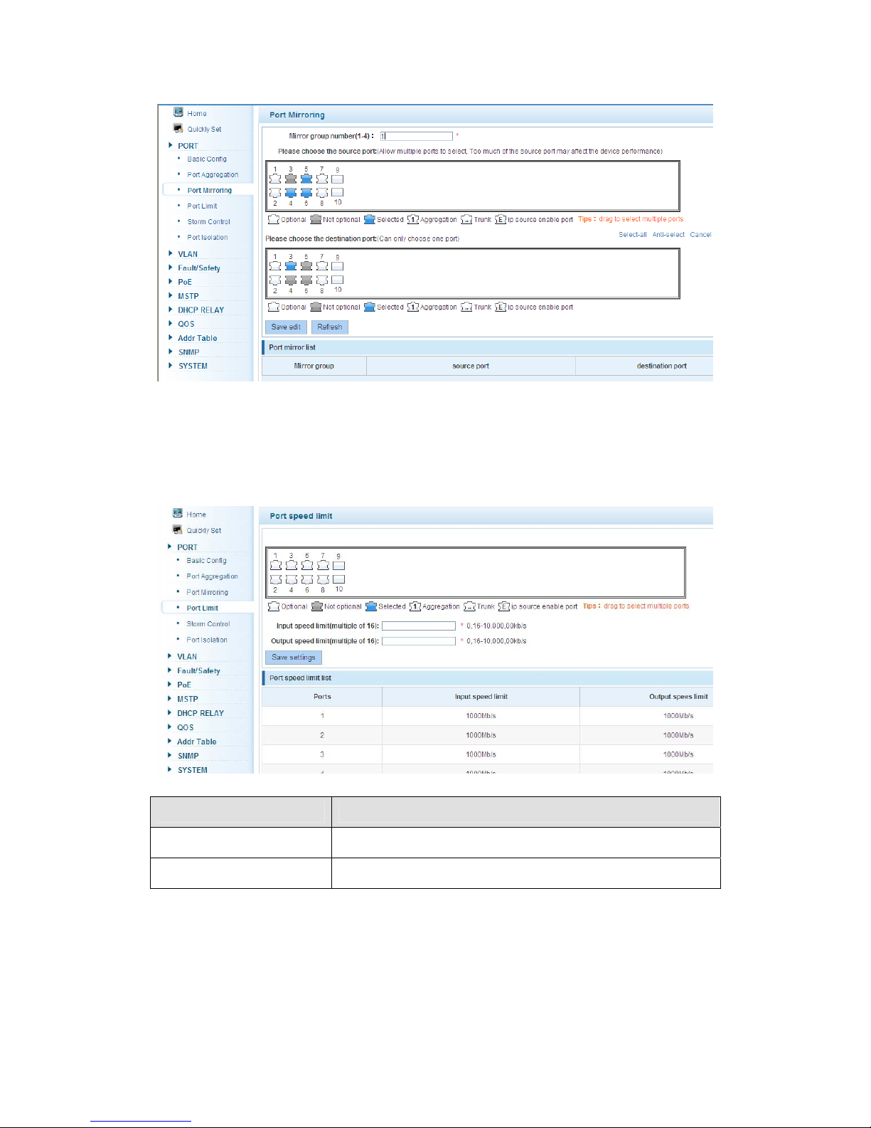
4.2.4 Port rate-limit
In the navigation bar to select “PORT>Port Limit”. Limiting the speed of output and input
rate of the ports, the following picture:
【Parameter Description】
Parameter Description
Input speed limit Set port input speed
Output speed limit Set port output speed
【Instructions】
1 Mbit/s = 1000 Kbit/s = 1000 / 8 KB/s = 125 KB/s. That is, the theoretical rate of 1M
bandwidth is 125 KB/s.
【Configuration example】
Such as: the port 5 input rate is set to 6400 KB/s, the output rate is set to 3200 KB/s.
19

4.2.5 Storm control
In the navigation bar to select “PORT>Storm Control”, to port storm control config, the
following ficture:
【Parameter Description】
Parameter
Broadcast
suppression value
Multicast suppression
value
Unicast suppression
value
【Instructions】
1 Mbit/s = 1000 Kbit/s = 1000 / 8 KB/s = 125 KB/s. That is, the theoretical rate of 1M
bandwidth is 125 KB/s.
【Configuration example】
Description
Storm suppression value of the broadcast packets
Storm suppression value of the multicast packets
Storm suppression value of the unicast packets
20

Such as: should be forwarded to the port 1-8 of all kinds of packet forwarding rate is 5000
KB/s.
4.2.6 Port isolation
In the navigation bar to select “PORT>port isolation”, the following picture:
【Parameter Description】
Parameter
Description
Source port Choose a port, to configure the isolated port
Isolated port
Port will be isolated
【Instructions】
Open port isolation function, All packets on the source port are not forwarded from the
isolated port, the selected ports are isolated. Ports that have been added to the aggregate
port aren't also capable of being a destination port and source port, destination port and
source port cannot be the same.
【Configuration example】
21
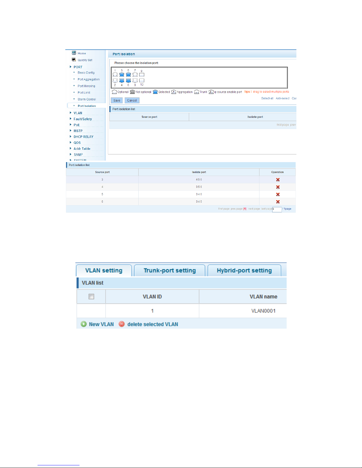
Such as: the port 3, 4, 5, and 6 ports isolated.
4.3 VLAN
In the navigation bar to select “VLAN”. You can manage the VLAN config, Trunk Settings
and Hybrid Settings, the following picture:
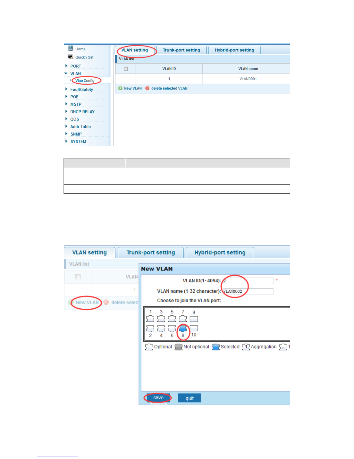
4.3.1 VLAN config
In the navigation bar to select “VLAN config”, Vlans can be created and set the port to the
VLAN (port default state for the access mode), the following picture:
22
【Parameter Description】
Parameter Description
VLAN ID VLAN number, 8GE default VLAN 1
VLAN name VLAN mark
VLAN IP address Manage switch ip address
【Instructions】
Management VLAN, the default VLAN cannot be deleted. Add ports as access port, port
access mode can only be a member of the VLAN.
【Configuration example】
Such as: connecting the same switches, pc1, pc2 couldn't ping each other, because one
of the PC connection port belongs to a VLAN 2.
23
 Loading...