

Morningstar TS-M-2, TS-RM-2 User Manual

RI
T
Digital Meters
Installation and Operation Manual
Version: TS-M-2
Version: TS-RM-2
S
TAR
8 Pheasant Run
Newtown, PA 18940 USA
email: info@morningstarcorp.com
www.morningstarcorp.com
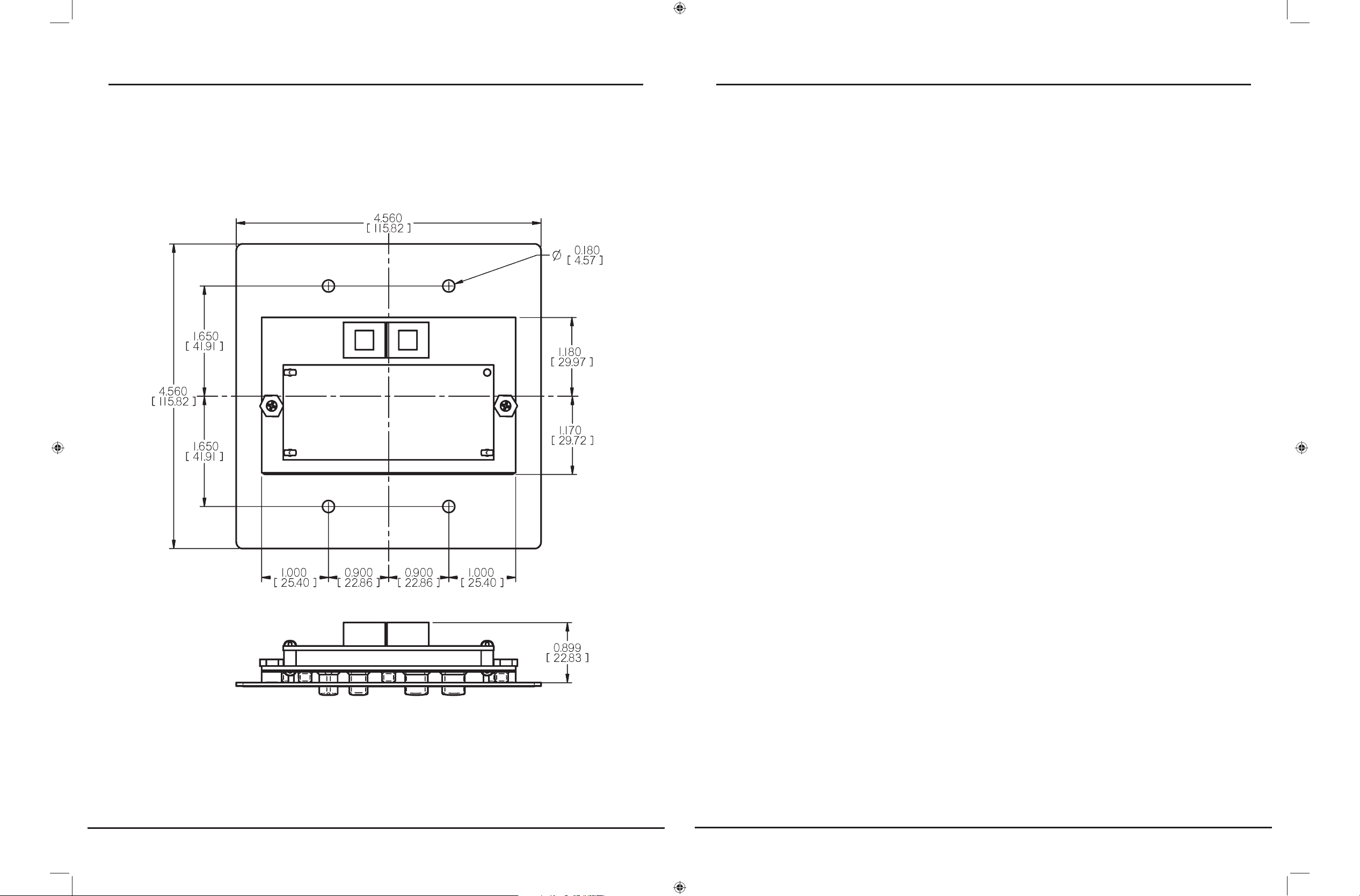
TS-RM-2 Dimensions in inches [mm] Contents
1.0 Important Safety Information 4
2.0 Meter Description 6
2.1 Meter Versions 7
2.2 General Use 7
3.1 General Information 9
3.0 Installation 9
3.2 TS-M-2 Install (single TriStar) 10
3.3 TS-RM-2 Install (single TriStar) 12
3.4 Multi-TriStar Network Setup 14
4.0 Operation 21
4.1 Backlighting 22
4.2 Single TriStar System 23
4.3 TriStar MeterBus Networks 35
5.0 Troubleshooting 40
6.0 Warranty 43
7.0 Technical Specifi cations 44
2 3TriStar Meter 2 Operator’s Manual
Installation Safety Precautions (Local Meter)
1.0
Important Safety Information
Save These Instructions
This manual contains important safety, installation and operating instructions for the TriStar Meter 2 digital displays.
The following symbols are used throughout this manual to
indicate potentially dangerous conditions or mark important
safety instructions:
WARNING:
Indicates a potentially dangerous condition. Use extreme
caution when performing this task.
Disconnect all power sources from the controller before mounting •
the TS-M-2 local meter.
Use the supplied RJ-11 meter cable to connect the meter to the •
controller.
Bend the power conductors in the conduit wiring box so that they •
do not touch the back of the meter.
Apply silicon gel to the RJ-11 connections on the meter and the •
controller for maximum protection from corrosion.
Installation Safety Precautions (Remote Meter)
Disconnect all power sources from the controller before opening •
the conduit box to connect the meter.
Mount the TriStar Meter 2 indoors. Prevent exposure to the ele-•
ments and do not allow water to enter the meter.
CAUTION:
!
Indicates a critical procedure for safe and proper operation of the controller.
NOTE:
Indicates a procedure or function that is important for the
safe and proper operation of the controller.
Safety Information
Read all of the instructions and cautions in the manual before •
beginning installation.
There are no user serviceable parts inside the TriStar Meter 2. Do •
not disassemble or attempt to repair.
There are no fuses or disconnects inside the TriStar Meter 2. Do •
not attempt to repair.
Protect the RJ-11 wiring with grommets, conduit, and wire clips as •
necessary.
Apply silicon gel to the RJ-11 connections on the meter and the •
controller for maximum protection from corrosion.
About this Manual
This manual provides detailed installation and usage instructions for the TriStar Meter 2 digital meters. Only qualifi ed
electricians and technicians who are familiar with solar system
design and wiring practices should install the TriStar Meter 2.
The usage information in this manual is intended for the system owner/operator.
4 Important Safety Information 5TriStar Meter 2 Operator’s Manual

2.0
TriStar controllers are technically advanced and professional
solar battery chargers and load controllers. Two digital LCD
meters are available for the TriStar family of controllers, and
Meter Description
2.1 Meter Versions
This manual covers two standard versions of a digital LCD
meter that can be used with the TriStar family of solar controllers.
their displays are identical. One version is mounted on the
controller; the other is mounted in a remote location.
This manual will help you to become familiar with the TriStar
meters’ features and capabilities. Some of these follow:
Intertek ETL Recognized for use with Morningstar’s TriStar family •
of charge controllers
Complies with CE and LVD standards•
Suitable for 12, 24, 48 Vdc systems •
Fully protected from wiring faults•
Controller-mounted and remote versions can be used together•
o
Extended LCD temperature rating (-20•
Multilingual display (English, French, German, Portuguese, Span-•
C to +70oC)
Version TS-M-2:
This local meter is provided as an assembly that replaces the
TriStar front access cover. The TS-M-2 meter mounts to the
TriStar controller.
Version TS-RM-2:
This remote meter is provided with a mounting plate and 30m
(98.4 ft) of cable. It is identical to the TS-M-2 version except
that the TS-RM-2 version can be mounted at some distance
from the controller.
Both meters can display the full range of operating and diagnostic information for the TriStar’s battery charging, load and
diversion operating modes.
ish)
Displays aggregate system data from multiple TriStar controllers•
Manual Ah resets and equalization control for individual control-•
lers and for multi-controller systems
Diagnostic capabilities•
View internal logged data stored in TriStar controllers that have •
datalogging capability
Remote version supplied with 30m (98.4 ft), cable may be short-•
ened if needed
Connections are by standard RJ-11 6-position modular plugs•
5-year standard warranty•
2.2 General Use
The meter will display a great deal of information about the
TriStar controller and the operation of your system. In addition, the meters enable manual functions and controller diagnostics. These capabilities will increase your confi dence that
the system is working properly and will help you to improve
system reliability, battery life, and system performance. It is
worth the time getting to know your meter!
The organization of the display screens is described in Section
6 Meter Description 7TriStar Meter 2 Operator’s Manual
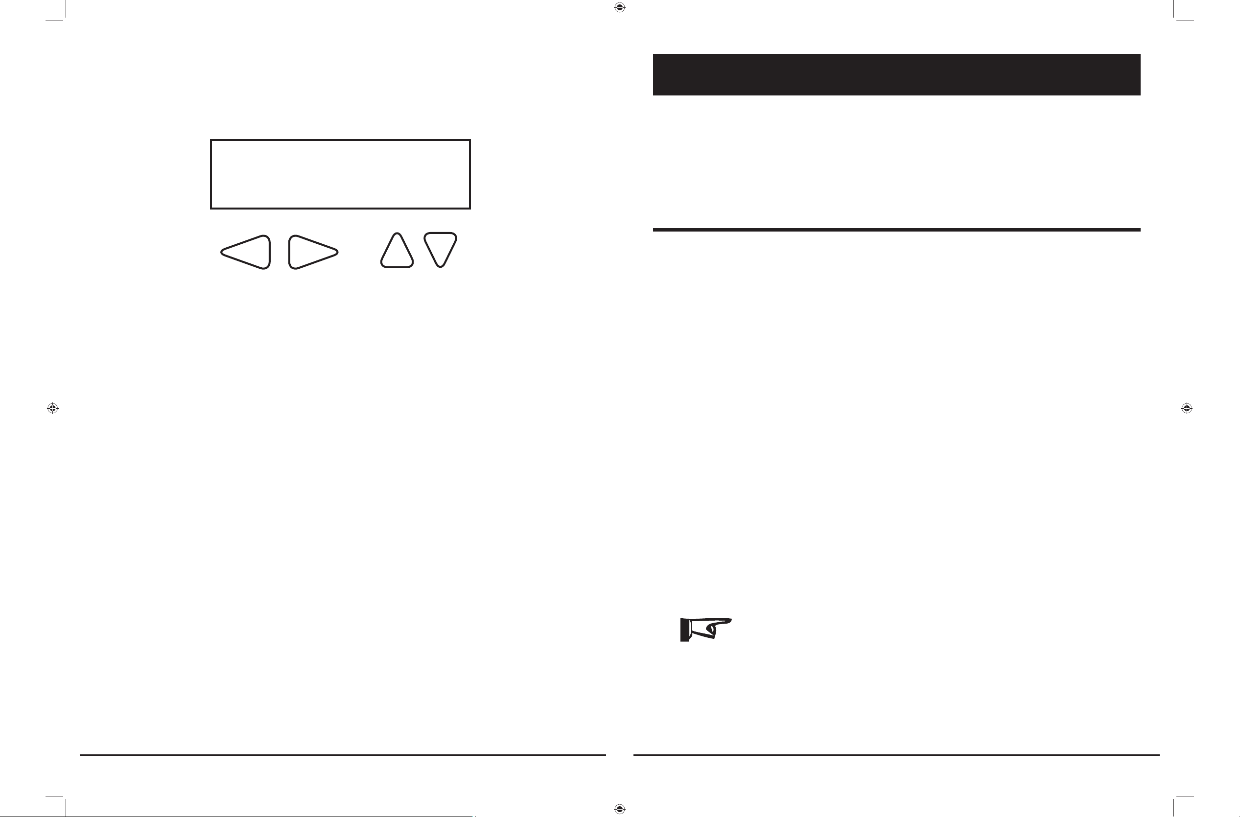
4.0. It is easy to move around the various display areas and
to scroll up or down, and left or right using the four pushbuttons as indicated below:
LEFT RIGHT UP DOWN
Due to power requirements, there is a limit of two meters that
can be used with a single TriStar controller. There is also a
limit of fi ve meters per MeterBus network. Any combination of
local and remote meter is permitted. Only one meter can have
an active backlight at any given time.
3.0
The TriStar meters can be added to the controller when it is
fi rst installed, or at anytime after the controller has been in
service.
Installation
3.1 General Information
The installation steps will differ depending on the number of
TriStar controllers in the system.
For Single TriStar Systems:
Mount the meter to the TriStar (TS-M-2) or in a remote location •
(TS-RM-2)
Connect the meter cable to the RJ-11 connectors•
adjust the meter settings•
For Systems with 2 or More TriStar Controllers:
Use a meter or MSView PC software to adjust the MeterBus ad-•
dress of each TriStar controller in the system.
Mount the meter to the TriStar (TS-M-2) or in a remote location •
(TS-RM-2).
Connect the meter(s) and controllers to a HUB-1 (sold separately)•
adjust the meter settings•
NOTE:
A TriStar meter may be connected to each TriStar in a
multi-TriStar system without the use of a HUB-1. This
confi guration will not provide total system information;
each meter will only display the information for one
controller.
8 Meter Description 9TriStar MPPT Operator’s Manual
NOTE:
socket on the TriStar. Looking at the back of the meter,
Both meters are rated for indoor use only.
There is a limit of two meters per single TriStar, fi ve meters per
MeterBus network. A single controller cannot power 3 meters.
When connected to a TriStar, the meter will automatically
display the correct operating mode (Solar Charging / Load /
Diversion). No adjustments to the meter are required.
If replacing or extending the meter cable, see Section 5.2.
3.2 TS-M-2 Install (single TriStar)
connect to the left RJ-11 socket.
To install the local controller-mounted meter to a single TriStar,
follow these steps in order:
CAUTION: Risk of Shock
!
!
Disconnect all power to the TriStar. The meter will
not be damaged if connected with power, but power
should be disconnected before the access cover is
removed for safety.
CAUTION: Equipment Damage
Do not allow the local meter to hang or dangle from
the RJ-11 cable when connected to the TriStar. The
resulting stress on the cable could damage the meter
or connectors.
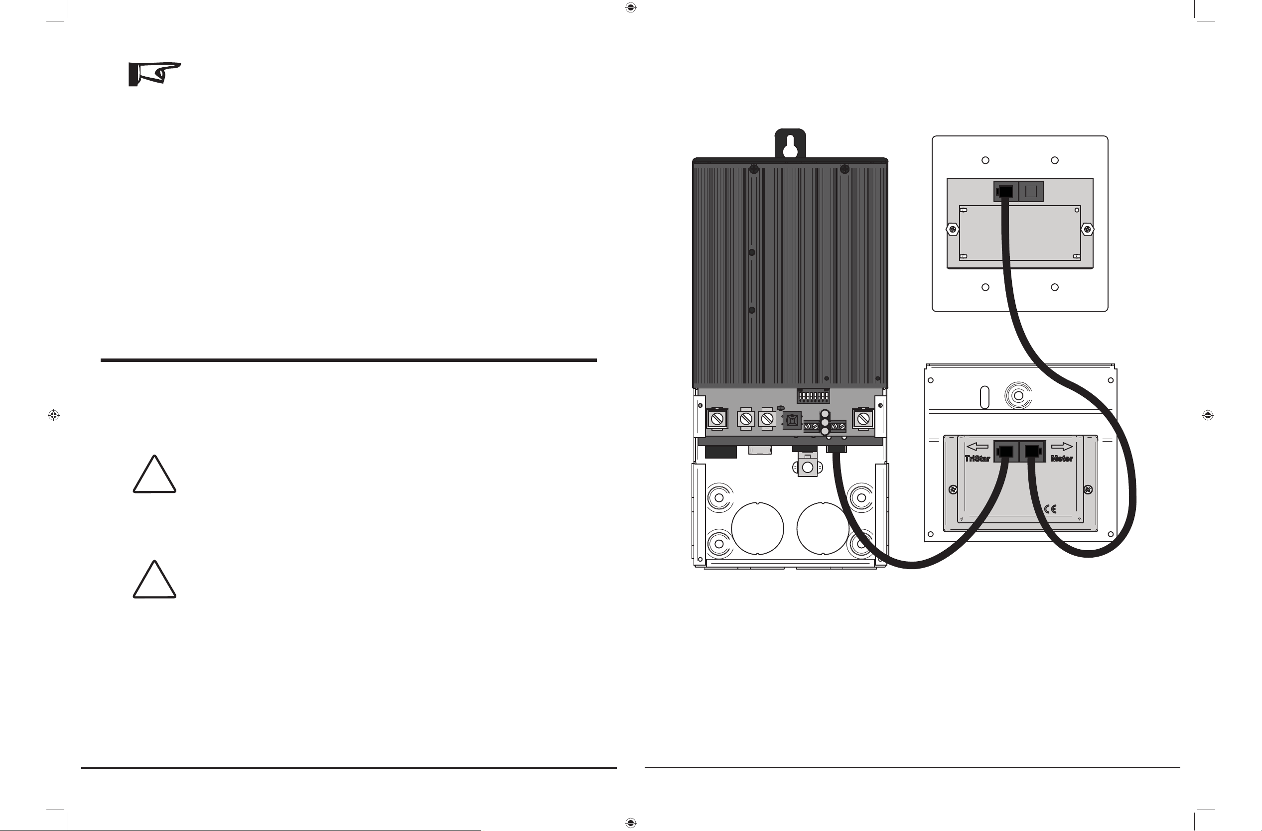
Figure 3-1. Meter connections
Use a large phillips screwdriver to remove the 4 access 1.
cover screws.
Connect the RJ-11 cable to the meter and to the RJ-11 2.
10 Installation 11TriStar Meter 2 Operator’s Manual
NOTE:
If the cable is connected to the wrong RJ-11 meter
Mount the meter to the wall or cabinet. If a 2-gang box is 4.
not being used, cut a hole in the wall or cabinet sized per
socket, there will not be any damage and the LCD
display will remain blank. Move the cable connection
to the other socket.
Carefully mount the TS-M-2 cover on the controller. Ar-3.
range the RJ-11 cable so that it does not interfere with
the pushbutton operation or obscure the view of the LED
indicators. Fasten the meter using the same 4 screws that
secured the blank access cover.
CAUTION: Equipment Damage
!
Do not force the cover into place. If the large power
wires are too high in the wiring compartment, pushing
the meter onto the wires will damage the meter.
the TS-RM-2 dimensions provided on the inside cover of
this manual.
NOTE:
2 remote meters can be installed if a TS-M-2 meter is
not attached to the TriStar controller.
3.3 TS-RM-2 Install (single TriStar)
The remote meter is designed to mount into a standard duplex
(2-gang) box, or fl ush against a wall or cabinet with a proper
sized hole.
Connect one end of the 30 meter cable to the TriStar RJ-11 1.
socket (or to the open socket if a TS-M-2 meter is mounted
to the TriStar).
Connect the other end of the cable to the left socket (look-2.
ing at the back) of the remote meter. See the diagram in
2.2.
Confi rm the meter is working before mounting the meter. 3.
12 Installation 13TriStar Meter 2 Operator’s Manual
 Loading...