

Morningstar TRISTAR TS-MPPT-60, TRISTAR TS-MPPT-45, TS-MPPT-30 Installation And Operation Manual
TM
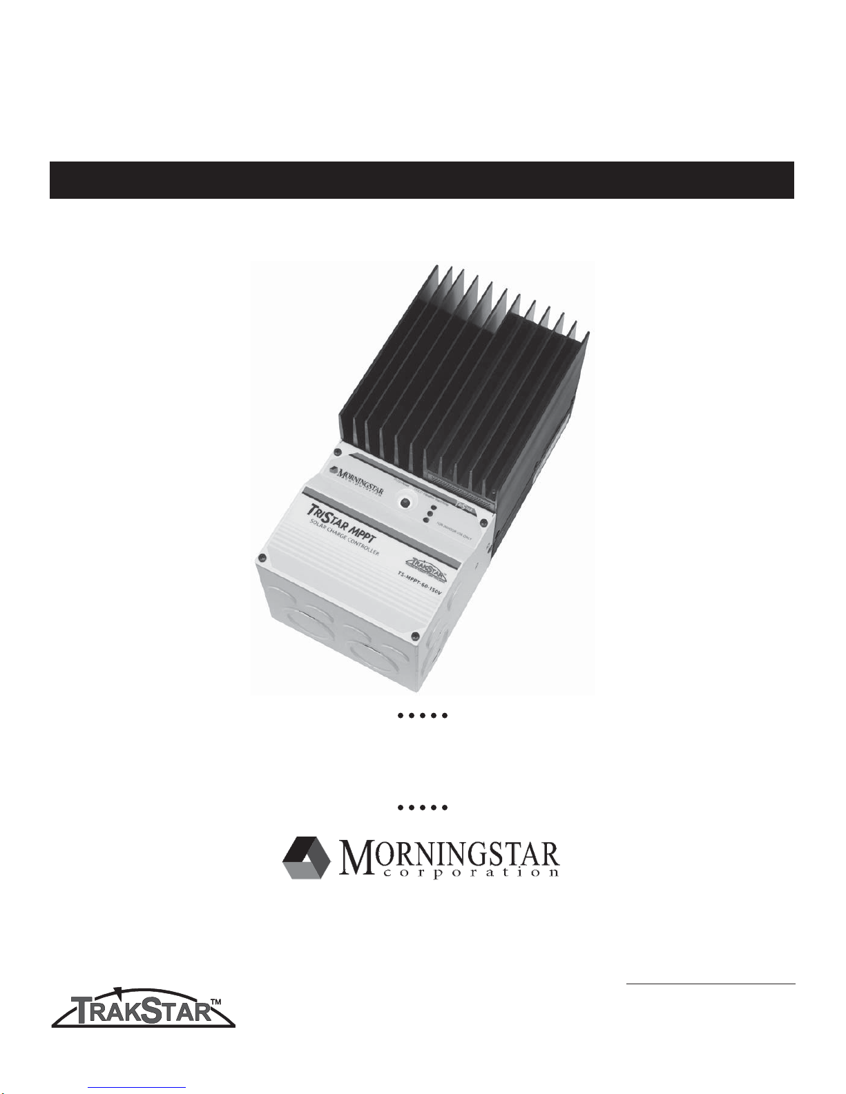
T
RI
S
TAR MPPT
Solar System Controller
Installation and Operation Manual
TrakStarTM Maximum Power Point Tracking Technology
MAXIMUM POWER POINT TRACKING
Solar Battery Charger
with
8 Pheasant Run
Newtown, PA 18940 USA
email: info@morningstarcorp.com
www.morningstarcorp.com
Models
TS-MPPT-60
TS-MPPT-45
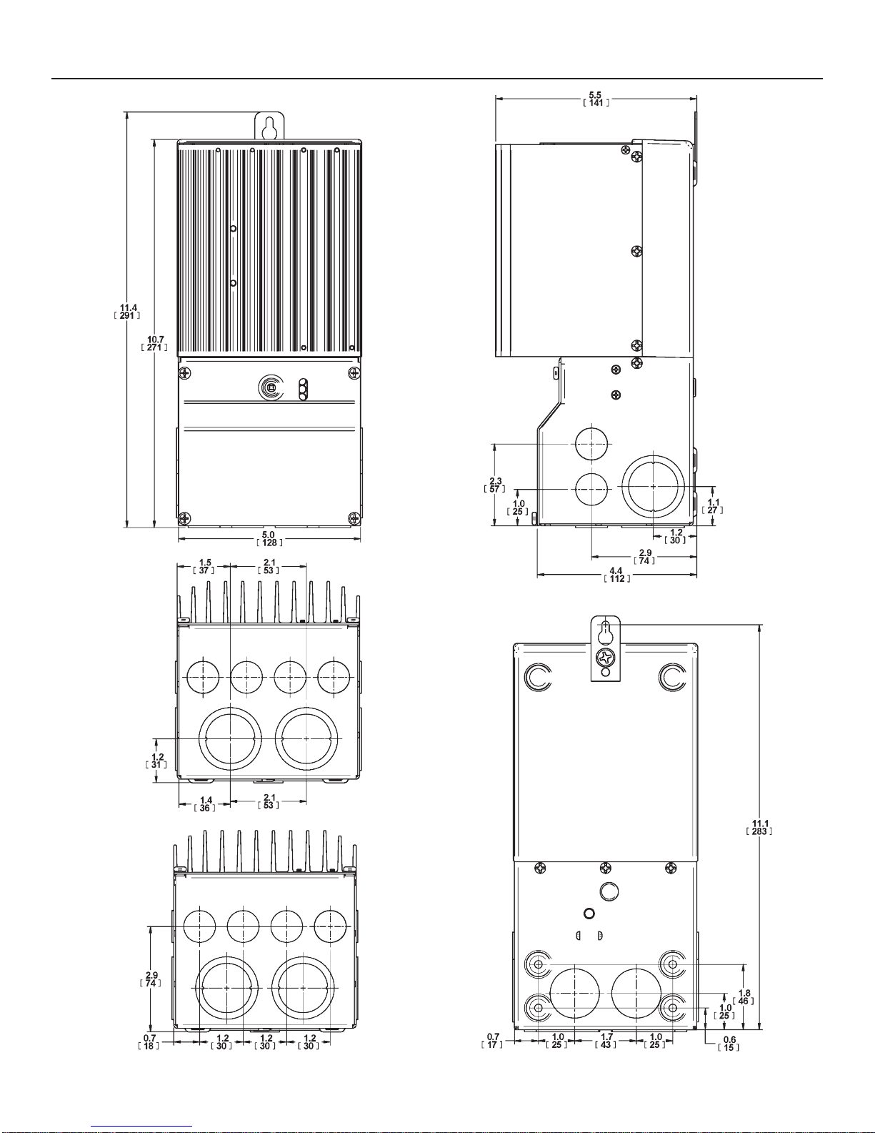
Dimensions in Inches [Millimeters]

Contents
1.0 Important Safety Information 4
2.0 Getting Started 8
2.1 Overview 8
2.2 Versions and Ratings 8
2.3 Features 9
2.4 Regulatory Information 11
2.5 Optional Accessories 12
3.0 Installation 13
3.1 General Information 13
3.2 Controller Installation 15
4.0 Operation 30
4.1 TrakStarTM MPPT Technology 30
4.2 Battery Charging Information 32
4.3 Push button 40
4.4 LED Indications 41
4.5 Protections, Faults & Alarms 43
4.6 Inspection and Maintenance 46
5.0 Networking and Communication 47
5.1 Introduction 47
5.2 Morningstar MeterBus
5.3 Serial RS-232 49
5.4 EIA-485 (formerly RS-485) 51
5.5 Ethernet 52
TM
48
6.0 Troubleshooting 55
7.0 Warranty 57
8.0 Specifi cations 58
1.0 Important Safety Information
Save These Instructions
This manual contains important safety, installation and operating instructions for the
TriStar MPPT solar controller.
The following symbols are used throughout this manual to indicate potentially dangerous conditions or mark important safety instructions:
WARNING:
Indicates a potentially dangerous condition. Use extreme caution when performing
this task.
CAUTION:
!
Indicates a critical procedure for safe and proper operation of the controller.
NOTE:
Indicates a procedure or function that is important for the safe and proper operation
of the controller.
AVERTISSEMENT :
Indique une condition potentiellement dangereuse. Faites preuve d’une prudence
extrême lors de la réalisation de cette tâche.
PRUDENCE :
!
Indique une procédure critique pour l’utilisation sûre et correcte du contrôleur.
REMARQUE :
Indique une procédure ou fonction importante pour l’utilisation sûre et correcte du
contrôleur.
Safety Information
• Read all of the instructions and cautions in the manual before beginning installation.
• There are no user serviceable parts inside the TriStar MPPT. Do not disassemble or attempt to repair the controller.
• Disconnect all sources of power to the controller before installing or adjusting the
TriStar MPPT.
• There are no fuses or disconnects inside the TriStar MPPT. Do not attempt to repair.
• Install external fuses/breakers as required.
Informations de sécurité
• Lisez toutes les instructions et les avertissements fi gurant dans le manuel avant de com-
mencer l’installation.
• Le TriStar MPPT ne contient aucune pièce réparable par l’utilisateur. Ne démontez pas ni
ne tentez de réparer le contrôleur.
• Déconnectez toutes les sources d’alimentation du contrôleur avant d’installer ou de régler
le TriStar MPPT.
• Le TriStar MPPT ne contient aucun fusible ou interrupteur. Ne tentez pas de réparer.
• Installez des fusibles/coupe-circuits externes selon le besoin.
4 Important Safety Information
Installation Safety Precautions
WARNING:
This unit is not provided with a GFDI device. This charge controller must be used with an
external GFDI device as required by the Article 690 of the National Electrical Code for
the installation location.
• Mount the TriStar MPPT indoors. Prevent exposure to the elements and do not allow water to enter the controller.
• Use insulated tools when working with batteries.
• Avoid wearing jewelry during installation.
• The battery bank must be comprised of batteries of same type, make, and age.
• Do not smoke in the vicinity of the battery bank.
• Power connections must remain tight to avoid excessive heating from a loose connection.
• Use properly sized conductors and circuit interrupters.
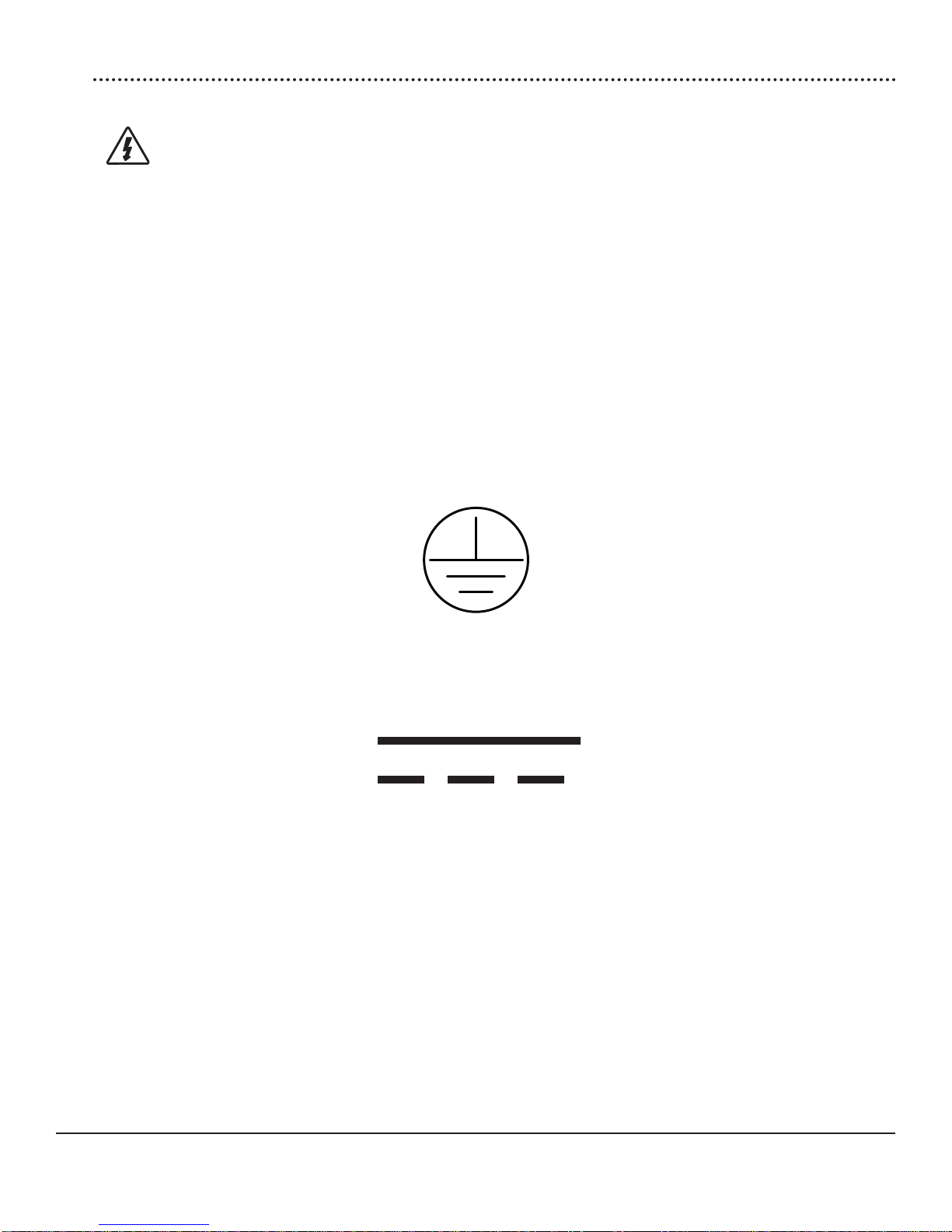
• The grounding terminal is located in the wiring compartment and is identifi ed by the sym-
bol below.
Ground Symbol
• This charge controller is to be connected to DC circuits only. These DC connections are
identifi ed by the symbol below.
Direct Current Symbol
5TriStar MPPT Operator’s Manual
AVERTISSEMENT :
L’appareil n’est pas fourni avec un dispositif GFDI. Ce contrôleur de charge doit être
utilisé avec un dispositif GFDI externe tel que requis par l’Article 690 du Code électrique
national de l’emplacement de l’installation.
• Montez le TriStar MPPT à l’intérieur. Empêchez l’exposition aux éléments et la pénétration
d’eau dans le contrôleur.
• Utilisez des outils isolés pour travailler avec les batteries.
• Évitez le port de bijoux pendant l’installation.
• Le groupe de batteries doit être constitué de batteries du même type, fabricant et âge.
• Ne fumez pas à proximité du groupe de batteries.
• Les connexions d’alimentation doivent rester serrées pour éviter une surchauffe excessive
d’une connexion desserrée.
• Utilisez des conducteurs et des coupe-circuits de dimensions adaptées.
• La borne de mise à la terre se trouve dans le compartiment de câblage et est identifi ée
par le symbole ci-dessous.
• Ce contrôleur de charge ne doit être connecté qu’à des circuits en courant continu. Ces
connexions CC sont identifi ées par le symbole ci-dessous.
Le contrôleur TriStar MPPT doit être installé par un technicien qualifi é conformément aux règle-
mentations électriques du pays où est installé le produit.
Un moyen d’assurer la déconnexion de tous les pôles de l’alimentation doit être fourni. Cette
déconnexion doit être incorporée dans le câblage fi xe.
À l’aide de la borne de mise à la masse du TriStar MPPT (dans le compartiment de câblage), un
moyen permanent et fi able de mise à la terre doit être fourni. La fi xation de la mise à la terre doit
être fi xée contre tout desserrage accidentel.
Les ouvertures d’entrée au compartiment de câblage du TriStar MPPT doivent être protégées
avec un conduit ou une bague.
6
Important Safety Information

About this Manual
This manual provides detailed installation and usage instructions for the TriStar MPPT controller.
Only qualifi ed electricians and technicians who are familiar with solar system design and wiring
practices should install the TriStar MPPT. The usage information in this manual is intended for
the system owner/operator.
7TriStar MPPT Operator’s Manual

Getting Started2.0
2.1 Overview
Thank you for selecting the TriStar MPPT solar charge controller with TrakStarTM MPPT Technology. The TriStar MPPT (TS-MPPT) is an advanced maximum power point tracking solar battery
charger. The controller features a smart tracking algorithm that fi nds and maintains operation at
the solar array peak power point, maximizing energy harvest.
The TriStar MPPT battery charging process has been optimized for long battery life and improved system performance. Self-diagnostics and electronic error protections prevent damage
when installation mistakes or system faults occur. The controller also features eight (8) adjustable
settings switches, several communication ports, and terminals for remote battery temperature
and voltage measurement.
Please take the time to read this operator’s manual and become familiar with the controller. This
will help you make full use of the many advantages the TriStar MPPT can provide for your PV
system.
2.2 Versions and Ratings
There are two versions of TriStar MPPT controllers.
TriStar-MPPT-45
• maximum 45 amps continuous battery current
• 12, 24, 36, and 48 Volt dc systems
• maximum 150 Volt dc solar input voltage
• RS-232 and MeterBus
TriStar-MPPT-60
• maximum 60 amps continuous battery current
• 12, 24, 36, and 48 Volt dc systems
• maximum 150 Volt dc solar input voltage
• RS-232, EIA-485, MeterBus
To comply with the National Electric Code (NEC), the current rating of the controller must be
equal to or greater than 125% of the solar array’s short circuit current output (Isc). Therefore, the
maximum allowable solar array input to the TriStar MPPT controller for compliance with the NEC
is:
TS-MPPT-45: 36 amps Isc*
TS-MPPT-60: 48 amps Isc*
TM
communication ports
TM
, and Ethernet communication ports
*Solar array Isc @ STC
8TriStar MPPT Operator’s Manual
2.3 Features
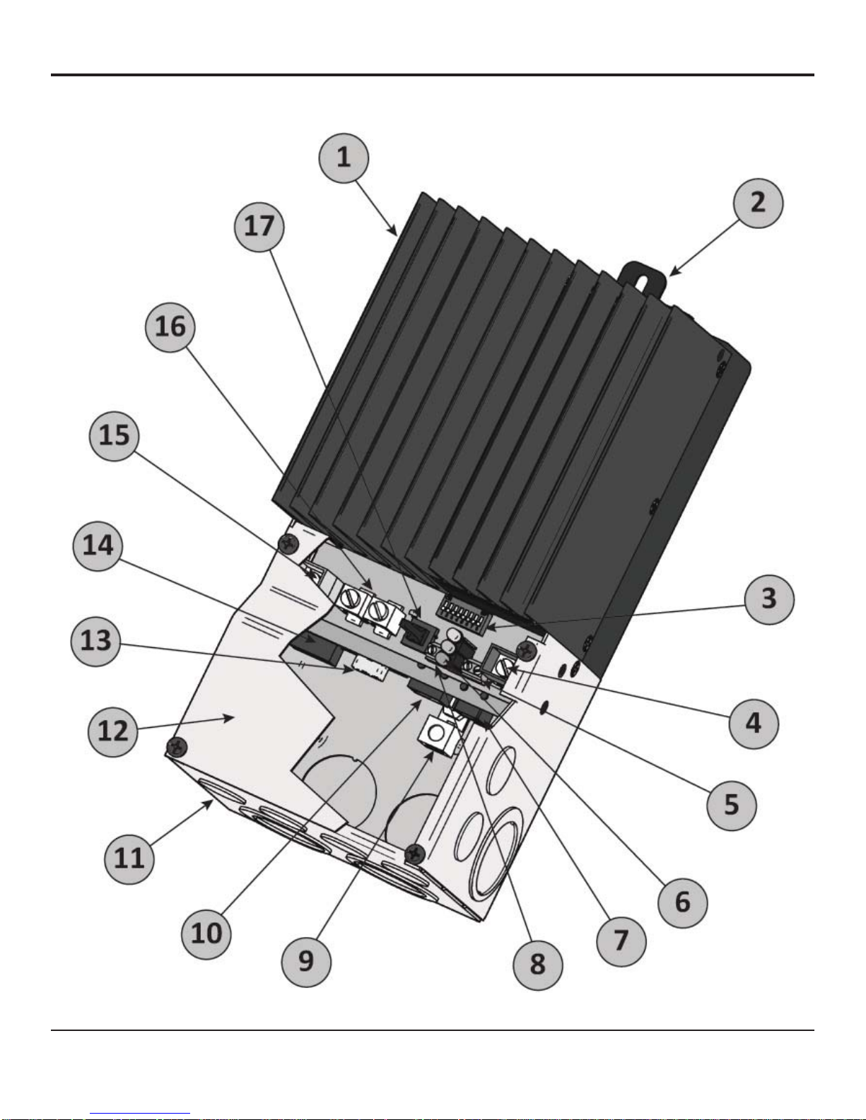
The features of the TriStar MPPT are shown in Figure 2-1 below. An explanation of each feature
is provided.
Figure 2-1. TriStar MPPT features
9TriStar MPPT Operator’s Manual

1 - Heatsink
Aluminum heatsink to dissipate controller heat
2 - Mounting Hanger
Keyhole slot for mounting
3 - Settings Switches
Eight (8) settings switches to confi gure operation of the TriStar MPPT
4 - Battery Positive Terminal (red)
Power connection for Battery (+)
5 - Remote Temperature Sensor Terminals
Connection point for a Morningstar RTS (optional) to remotely monitor battery temperature
6 - LED Indicators
Three state of charge (SOC) LED indicators show charging status and controller faults
7 - MeterBusTM Port
RJ-11 socket for Morningstar MeterBusTM network connections
8 - Battery Voltage Sense Terminals
Terminals for battery voltage input provide accurate battery voltage measurement
9 - Ground Terminal
A chassis ground terminal for system grounding
10 - Ethernet Port
RJ-45 socket for LAN/internet connections (TS-MPPT-60 model only)
11 - Wiring Box with Conduit Knockouts
Termination points for wiring conduit and wire glands
12 - Wiring Box Cover
Sheet metal wiring box cover protects power connections
13 - Serial RS-232 Port
9-pin serial connector (female)
14 - EIA-485 Port
Four (4) position screw terminal for EIA-485 bus connections (TS-MPPT-60 model only)
15 - Solar Positive Terminal (yellow)
Power connection for Solar (+)
16 - Common Negative Power Terminals
Two (2) negative terminals for negative system cable termination
17 - Push-button Switch
Manually reset from an error or fault, also used to start/stop a manual equalization.
10
Getting Started

2.4 Regulatory Information
NOTE:
This section contains important information for safety and
regulatory requirements.
The TriStar MPPT controller should be installed by a qualifi ed technician according to the electri-
cal rules of the country in which the product will be installed.
TriStar MPPT controllers comply with the following EMC standards:
• Immunity: EN61000-6-2:1999
• Emissions: EN55022:1994 with A1 and A3 Class B1
• Safety: EN60335-1 and EN60335-2-29 (battery chargers)
A means shall be provided to ensure all pole disconnection from the power supply. This disconnection shall be incorporated in the fi xed wiring.
Using the TriStar MPPT grounding terminal (in the wiring compartment), a permanent and reliable means for grounding shall be provided. The clamping of the earthing shall be secured
against accidental loosening.
The entry openings to the TriStar MPPT wiring compartment shall be protected with conduit or
with a bushing.
FCC requirements:
This device complies with Part 15 of the FCC rules. Operation is subject to the following two conditions: (1) This
device may not cause harmful interference, and (2) this device must accept any interference received, including
interference that may cause undesired operation.
Changes or modifi cations not expressly approved by Morningstar for compliance could void the user’s authority to
operate the equipment.
Note:
This equipment has been tested and found to comply with the limits for a Class B digital device, pursuant to Part 15
of the FCC rules. These limits are designed to provide reasonable protection against harmful interference in a residential installation. This equipment generates, uses, and can radiate radio frequency energy and, if not installed and
used in accordance with the instruction manual, may cause harmful interference to radio communication. However,
there is no guarantee that interference will not occur in a particular installation. If this equipment does cause harmful
interference to radio or television reception, which can be determined by turning the equipment on and off, the user
is encouraged to try to correct the interference by one or more of the following measures:
• Reorient or relocate the receiving antenna.
• Increase the separation between the equipment and receiver.
• Connect the equipment into an outlet on a circuit different from that to which the receiver is connected.
• Consult the dealer or an experienced radio/TV technician for help.
This Class B digital apparatus complies with Canadian ICES-003.
Cet appareil numerique de la classe B est conforme a la norme NMB-003 du Canada.
11TriStar MPPT Operator’s Manual

2.5 Optional Accessories
The following accessories are available for purchase separately from your authorized Morningstar dealer.
TriStar Digital Meter 2 / TriStar Remote Meter 2 (Models: TS-M-2 / TS-RM-2)
The TriStar Digital Meter mounts directly on the TS-MPPT controller, replacing the wiring box
cover. The TriStar Remote Meter can be fl ush mounted in a wall or into a standard duplex (2-
gang) electrical box. A 2 x 16 character display shows system operating information, error indications, and self-diagnostic information. Four (4) buttons make navigating the meter menus easy.
For systems where multiple TS-MPPT controllers are networked together, one (1) meter can
display full system information. The TriStar meters connect to the RJ- 11 MeterBusTM port on the
TriStar-MPPT.
Meter Hub (HUB-1)
A Morningstar MeterBusTM network with multiple controllers requires a Meter Hub for electrical
isolation. The HUB-1 allows communication between MeterBusTM compatible Morningstar products, including the TriStar MPPT controller. DIN rail compatible. See section 5.2 for more details.
Relay Driver (RD-1)
The Relay DriverTM accessory enables the TriStar MPPT to control external devices. Four (4)
relay control ports can be confi gured (in various combinations) to perform the following tasks:
• generator control (2-, 3-, and 4-wire confi gurations)
• dry contacts for alarms and other signals
• advanced load control
• vent fan control
• DIN rail compatible or surface mount
For more information on the Relay Driver, visit our website at www.morningstarcorp.com or inquire with your local Morningstar dealer.
EIA-485 / RS-232 Communications Adapter (RSC-1)
Connect one or more TriStar MPPT controllers to a PC or to other serial devices using the RSC-1
EIA-485 adapter. The adapter converts an RS-232 serial interface to EIA-485 compliant signals.
An LED shows network activity and errors. DIN rail compatible.
12
Getting Started
Installation3.0
3.1 General Information
The mounting location is important to the performance and operating life of the controller. The
environment must be dry and protected from water ingress. If required, the controller may be installed in a ventilated enclosure with suffi cient air fl ow. Never install the TriStar MPPT in a sealed
enclosure. The controller may be mounted in an enclosure with sealed batteries, but never
with vented/fl ooded batteries. Battery fumes from vented batteries will corrode and destroy the
TriStar MPPT circuits.
Multiple TriStars can be installed in parallel on the same battery bank to achieve higher charging
current. Additional parallel controllers can also be added in the future. Each TriStar MPPT must
have its own solar array.
CAUTION: Equipment Damage or Risk of Explosion
Never install the TriStar MPPT in an enclosure with vented/fl ooded batteries. Battery
!
fumes are fl ammable and will corrode and destroy the TriStar MPPT circuits.
CAUTION: Equipment Damage
When installing the TriStar MPPT in an enclosure, ensure suffi cient ventilation.
!
Installation in a sealed enclosure will lead to over-heating and a decreased product
lifetime.
PRUDENCE : Endommagement de l’équipement ou risque d’explosion
N’installez jamais le TriStar MPPT dans une enceinte avec des batteries à évent/à
!
électrolyte liquide. Les vapeurs des batteries sont infl ammables et corroderont et
détruiront les circuits du TriStar MPPT.
PRUDENCE : Endommagement de l’équipement
Assurez une ventilation suffi sante en cas d’installation du TriStar MPPT dans une
!
enceinte. L’installation dans une enceinte hermétique entraîne une surchauffe et une
réduction de la durée de vie du produit.
The installation is straightforward, but it is important each step is done correctly and safely. A
mistake can lead to dangerous voltage and current levels. Be sure to carefully follow each instruction in this section. Read all instructions fi rst before beginning installation.
The installation instructions are for installation of a negative grounded system. National Electrical
Code (NEC) requirements are noted on occasion for convenience, however the installer should
have a complete understanding of NEC and UL requirements for photovoltaic installations.
13 Installation

Recommended Tools:
• Wire strippers
• Wire cutters
• #2 & #0 Phillips screwdriver
• slotted screwdrivers
• Pliers
• Drill
• 3/32” (2.5 mm) drill bit
• Level
• hack saw (cutting conduit)
14
Installation
3.2 Controller Installation
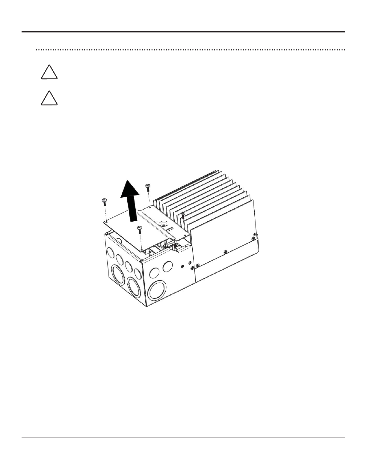
Step 1 - Remove the wiring box cover
CAUTION: Shock Hazard
Disconnect all power sources to the controller before removing the wiring box cover. Never
!
remove the cover when voltage exists on any of the TriStar MPPT power connections.
PRUDENCE : Risque de décharge électrique
Déconnectez toutes les sources d’alimentation du contrôleur avant d’enlever le couvercle
!
du boîtier de câblage. Ne retirez jamais le couvercle en présence de tension sur une des
connexions d’alimentation du TriStar MPPT.
Use a #2 Phillips screw driver to remove the four (4) screws that secure the wiring box cover as
shown in fi gure 3-1 below.
Figure 3-1. Remove the wiring box cover.
If a TriStar Digital Meter 2 display is installed, be sure to disconnect the RJ-11 cable.
15TriStar MPPT Operator’s Manual
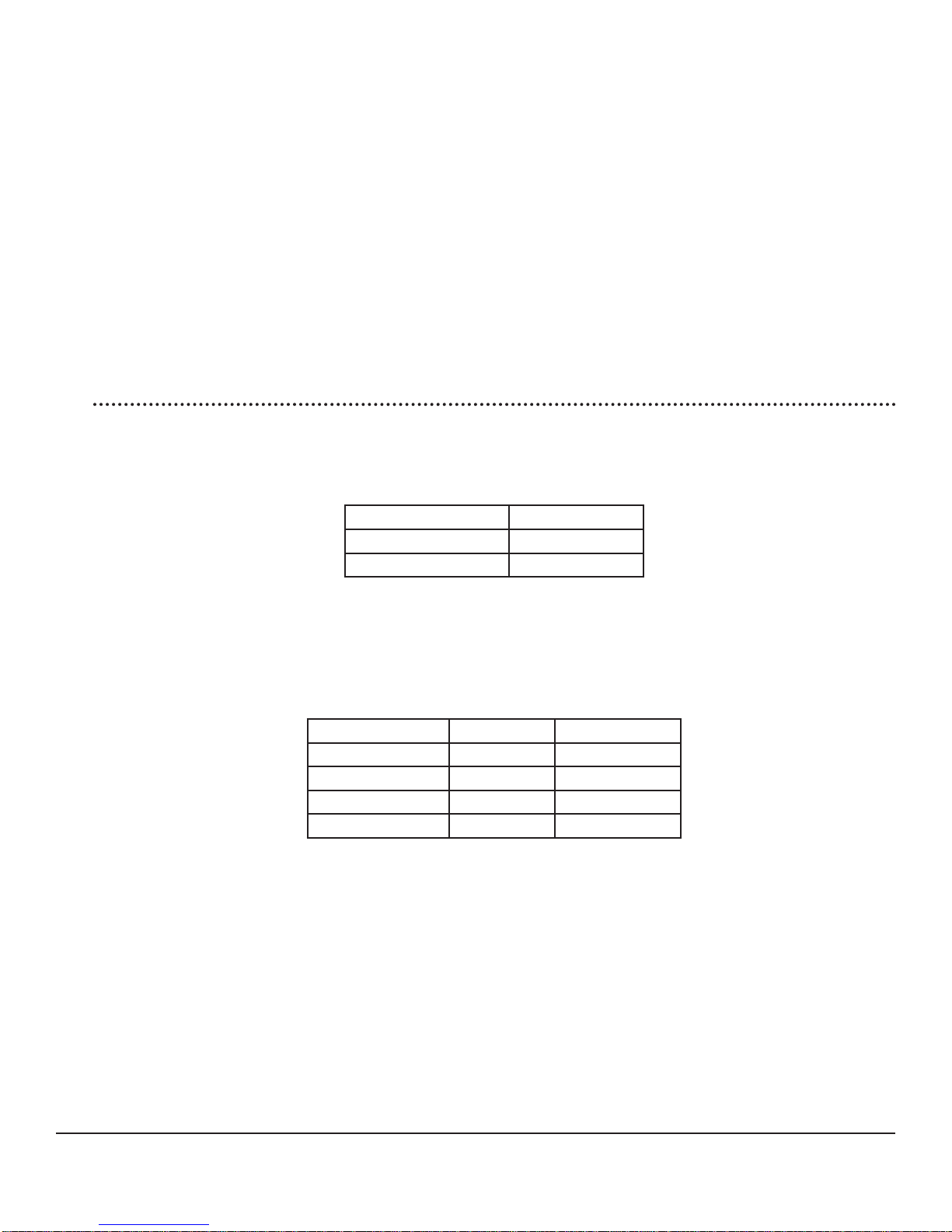
Step 2 - Remove the knockouts
Knockouts are provided for routing cables through conduit or wire glands. Table 3-1 below provides the knockout sizes and quantity on the TriStar MPPT wiring box. Knockout locations and
dimensions are on the inside front cover.
Quantity Trade Size Hole Dimension
8 1/2” or M20 7/8” (22.2 mm)
6 1 “ 1 - 23/64 “ (34.5 mm)
4 1 - 1/4 “ 1 - 23/32 “ (43.7 mm)
Table 3-1. Knockout sizes
CAUTION: Shock Hazard
Always use bushings, connectors, clamp connectors, or wire glands in the knockout openings to
!
protect wiring from sharp edges.
PRUDENCE : Risque de décharge électrique
Utilisez toujours des bagues, des connecteurs, des raccordements à collets ou des fouloirs dans
!
les ouvertures afi n de protéger le câblage des bords coupants.
CAUTION: Shock Hazard
!
Never route network cables in the same conduit as the power conductors.
PRUDENCE : Risque de décharge électrique
N’acheminez jamais les câbles réseau dans le même conduit que les conducteurs
!
d’alimentation.
Plan the routing of each conductor that will connect to the TriStar MPPT before removing any
knockouts. The 1/2” (M20) knockouts are ideal for routing network cables, which must be placed
in separate conduit.
16
Installation
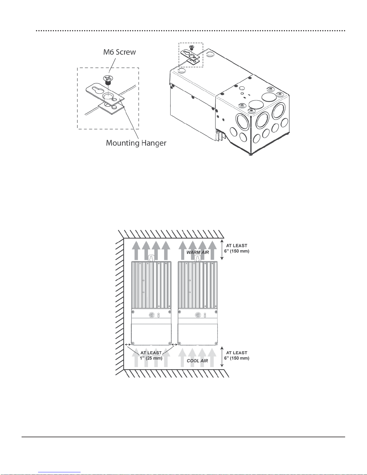
Step 3 - Mount to a Vertical Surface
Figure 3-2. Attaching the mounting hanger
1. Attach the mounting hanger to the bottom of the TriStar MPPT with the M6 screw provided as
shown in fi gure 3-2.
2. Place the TriStar MPPT on a vertical surface protected from direct sun, high temperatures,
and water. The TriStar MPPT requires at least 6” (150 mm) of clearance above and below
and at least 1” (25 mm) on each side for proper air fl ow as shown in fi gure 3-3 below.
Figure 3-3. Required mounting clearance for air fl ow.
3. Place a mark on the mounting surface at the top of the keyhole.
4. Remove the controller and drill a 3/32” (2.5 mm) hole at the drill mark.
5. Insert a #10 screw (included) into the top pilot hole. Do not tighten the screw completely.
Leave a 1/4” (6 mm) gap between the mounting surface and screw head.
17TriStar MPPT Operator’s Manual
6. Carefully align the keyhole on the TriStar MPPT with the screw head. Slide the TriStar MPPT
down over the keyhole.
7. Check for vertical plumb with a level.
8. Mark two (2) mounting hole locations in the wiring box.
9. Remove the controller and drill 3/32” (2.5 mm) holes at the drill marks.
10. Carefully align the keyhole on the TriStar MPPT with the screw head. Slide the TriStar MPPT
down over the keyhole.
11. The pre-drilled pilot holes should align with the mounting holes in the wiring box. Secure the
controller with two (2) #10 mounting screws.
12. Tighten the keyhole screw.
Step 4 - Adjust Settings Switches
Switch 1: Reserved for Future Use
Settings switch 1 should remain in the “OFF” position.
Mode Switch 1
Solar Charging OFF
future use ON
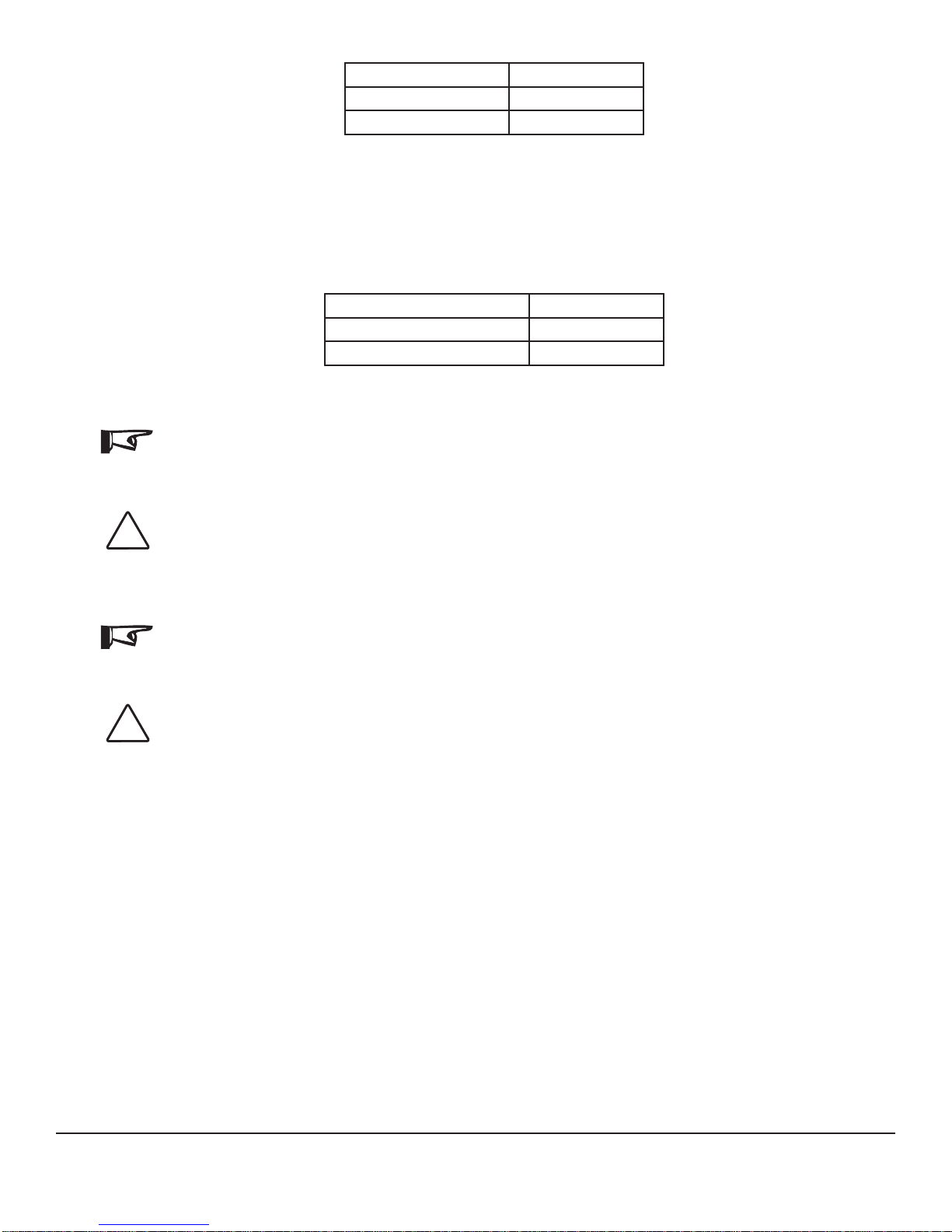
Switches 2 & 3: System Voltage
Four (4) system voltage confi gurations are available as shown in the table below:
System Voltage Switch 2 Switch 3
Auto OFF OFF
12 OFF ON
24 ON OFF
48 ON ON
The “auto” setting allows the TriStar MPPT to detect the system voltage automatically on start up.
The test is only performed at start up and the detected system voltage will never change during
operation.
Generally, it is best to choose a specifi c system voltage. The auto detect feature should only be
used in situations where the system voltage is unknown ahead of time or in systems where the
system voltage may change periodically.
18
Installation

Switches 4, 5, & 6: Battery Charging Settings
It is important to select the battery type that matches the system battery to ensure proper charging and long battery life. Refer to the specifi cations provided by the battery manufacturer and
choose a setting that best fi ts the recommended charging profi le.
Settings
Switches
4 - 5 - 6
off-off-off 1 - Gel 14.00 13.70
off-off-on 2 - Sealed* 14.15 13.70 14.40 28
off-on-off 3 - Sealed* 14.30 13.70 14.60 28
off-on-on 4 - AGM/Flooded 14.40 13.70 15.10 28
on-off-off 5 - Flooded 14.60 13.50 15.30 28
on-off-on 6 - Flooded 14.70 13.50 15.40 28
on-on-off 7 - L-16 15.40 13.40 16.00 14
on-on-on 8 - Custom Custom Custom Custom Custom
* “Sealed” battery type includes gel and AGM batteries
Battery
Type
Absorp.
Stage
(Volts)
Float
Stage
(Volts)
Equalize
Stage
(Volts)
Equalize
Interval
(Days)
All settings are for 12 Volt nominal systems. Multiply the charge voltage settings by 2 for 24 Volt
systems or by 4 for 48 Volt systems. A description of each setting is provided below. See section 4.3 for full details on battery charging and a description of each of the settings in the battery
charging table.
Battery Type - The most common battery type associated with the specifi ed charging settings.
Absorption Stage - This stage limits input current so that the Absorption voltage is maintained.
As the battery becomes more charged, the charging current continues to taper down until the
battery is fully charged.
Float Stage - When the battery is fully charged, the charging voltage will be reduced to the Float
voltage setting.
Equalize Stage - During an equalization cycle, the charging voltage will be held constant at the
specifi ed voltage setting.
Equalize Interval - The number of days between equalization charges when the controller is confi gured for automatic equalizations (settings switch 7).
Switch 7: Battery Equalization
Choose between manual and automatic battery equalization charging. In the manual equalization setting, an equalization will only occur when manually started with the pushbutton or when
requested from the equalize menu on the TriStar meter. Automatic equalization will occur according to the battery program specifi ed by settings switches 4, 5, & 6 in the previous step.
In both settings (auto and manual), the pushbutton can be used to start and stop battery equalization. If the selected battery charging setting does not have an equalization stage an equalization will never occur, even if requested manually.
19TriStar MPPT Operator’s Manual
Equalize Switch 7
manual OFF
automatic ON
Switch 8: Ethernet Security
The Ethernet Security switch enables or disables confi guration of the TriStar MPPT settings
through the Ethernet connection. When switch eight is set to disabled, write commands to the
TriStar MPPT custom memory are not allowed. This a safety feature to prevent unintended
changes to custom settings, but it is not a replacement for proper network security.
Confi guration via TCP/IP Switch 8
disabled OFF
enabled ON
NOTE:
Adjustment of network settings and custom setpoints is always enabled via the RS-232 and EIA485 connections. The Ethernet Security switch only enables/disables remote confi guration via
TCP/IP.
CAUTION: Risk of Tampering
The Ethernet Security settings switch does not block write commands to devices bridged via EIA-
!
485.
REMARQUE :
Le réglage des paramètres de réseau et des points de consignes personnalisés est toujours
activé par les connexions RS-232 et EIA-485. Le contacteur de sécurité Ethernet n’active/
désactive que la confi guration à distance par TCP/IP.
PRUDENCE : Risque de tentative d’altération
Le contacteur des paramètres de sécurité Ethernet ne bloque pas les commandes d’écriture sur
!
les dispositifs reliés par EIA-485.
20
Installation
Step 5 - Remote Temperature Sensor
The included Remote Temperature Sensor (RTS) is recommended for effective temperature compensated charging. Connect the RTS to the 2-position terminal located between the pushbutton and the LED’s (see fi gure 2-1). The RTS is supplied with 33 ft (10 m) of 22 AWG (0.34 mm2)
cable. There is no polarity, so either wire (+ or -) can be connected to either screw terminal. The
RTS cable may be pulled through conduit along with the power wires. Tighten the connector
screws to 5 in-lb (0.56 Nm) of torque. Separate installation instructions are provided inside the
RTS bag.
CAUTION:
!
The TriStar MPPT will not temperature compensate charging parameters if the RTS is not used.
CAUTION: Equipment Damage
Never place the temperature sensor inside a battery cell. Both the RTS and the battery will be
!
damaged.
NOTE:
The RTS cable may be shortened if the full length is not needed. Be sure to reinstall the ferrite
choke on the end of the RTS if a length of cable is removed. This choke ensures compliance with
electromagnetic emissions standards.
PRUDENCE :
Le TriStar MPPT ne compense pas la température des paramètres de charges si le RTS n’est
!
pas utilisé.
PRUDENCE : Endommagement de l’équipement
Ne placez jamais la sonde de température dans un élément de batterie. Le RTS et la batterie
!
seraient endommagés.
REMARQUE :
Le câble de RTS peut être raccourci si la totalité de la longueur n’est pas nécessaire. Assurezvous de réinstaller la bobine en ferrite sur l’extrémité du RTS si une longueur de câble est
enlevée. Cette bobine assure la conformité avec les normes d’émissions électromagnétiques.
21TriStar MPPT Operator’s Manual
 Loading...