

MORNINGSTAR SURESINE-300 installation Guide
300 Watt Pure Sine Wave Inverter
Installation and Operation Manual
Model DC Input AC Output
SI-300-115V 12 Vdc 115 V @ 60 Hz
SI-300-220V 12 Vdc 220 V @ 50 Hz
1098 Washington Crossing Road
Washington Crossing, Pennsylvania 18977 USA
email: info@morningstarcorp.com
website: www.morningstarcorp.com

Table of Contents
1.0 Safety Notes...................................................... 3
2.0 Overview............................................................ 4
3.0 Installation..........................................................5
4.0 Operation.........................................................11
5.0 Protections....................................................... 12
6.0 Maintenance.................................................... 13
7.0 Warranty ..........................................................14
8.0 Technical Specifications..................................15
2
1.0 Safety Notes
IMPORTANT SAFETY INSTRUCTIONS
SAVE THESE INSTRUCTIONS
This manual contains important safety, installation and operating instructions for
the Morningstar SureSine-300 Inverter.
The SureSine produces voltages and currents capable of causing severe injury
or death. Extreme caution must be taken when installing and using the SureSine.
The following symbols are used throughout this manual to indicate potentially
dangerous conditions or important safety instructions.
WARNING: Indicates a potentially dangerous condition.
CAUTION: Indicates a critical procedure for safe and proper
operation of the SureSine. Use extreme caution when performing
this task.
NOTE: Indicates a procedure or function that is important to the
safe and proper operation of the SureSine Inverter.
General Safety Information
Read all of the instructions and cautions in the manual before starting the
installation.
Ensure that battery power has been disconnected BEFORE installing,
servicing, or removing the SureSine Inverter.
Do not allow water to enter the SureSine.
3
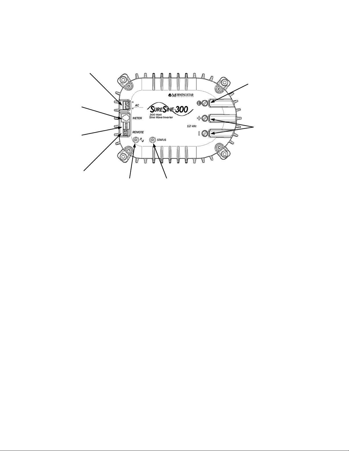
2.0 Overview
1. AC Output
Terminals
2. Remote Meter
RJ-11 Jack
3. DIP Switches
4. Remote On/Off
Terminal Contacts
Figure 1
5. AC Output
LED
6. Inverter Status
LED
8. Earth Ground
Terminal
7. 12V Battery
Input Terminals
1. AC Output Terminals – Wiring location for AC output
2. Remote Meter Jack – Communication port for Morningstar Remote Meter or
PC Communications**.
3. DIP Switches – Four switches to adjust operating parameters
4. Remote On/Off Contacts – Connection points for remote On/Off switch or
jumper wire
5. AC Output LED – Displays operating status of AC output
6. Inverter Status LED – Displays operating status of the SureSine
7. 12V Battery Input Terminals – Wiring location for 12V lead-acid battery input
8. Earth Ground – Wiring location for earth grounding or chassis grounding
** Adapter required, not included. See Morningstar website for more details.
4

3.0 Installation
Required Tools:
Wire cutters / strippers
Drill and 1/8” (3 mm) drill bit
Philips and Flat-head screw drivers
Required Parts (not included):
3A AC in-line fuse
100A DC in-line fuse
Toggle switch (if remote switch is used)
STEP 1 - Mounting
CAUTION - To prevent fire, do not mount in zero-clearance compartment.
Overheating may result.
Locate the SureSine on a surface that is protected from direct sun, high
temperatures, corrosive fumes, and water. SureSine may be mounted
horizontally on a flat surface (like a table) or vertically (on a wall). Do not install in
a confined area where battery gasses can accumulate.
Place the SureSine on the surface where it will be mounted and determine where
the wires will enter/exit. Be sure there is sufficient bending room for the wires and
other auxiliary connections. Verify that the mounting screws will not penetrate
wires or other objects located on the opposite side of the surface. With a pencil
or pen, mark the mounting hole locations
With a drill and 1/8” (3 mm) bit, drill pilot holes for each of the four mounting
screw locations marked on the mounting surface.
Place the SureSine onto the surface and align the mounting feet holes with the
four pilot holes. Use the included #10 screws to secure the SureSine to the
surface.
5
 Loading...