

MORNINGSTAR SUNSAVER DUO Operation Manual
TM
UNSAVER
S
D
UO
Installation and Operation Manual
….
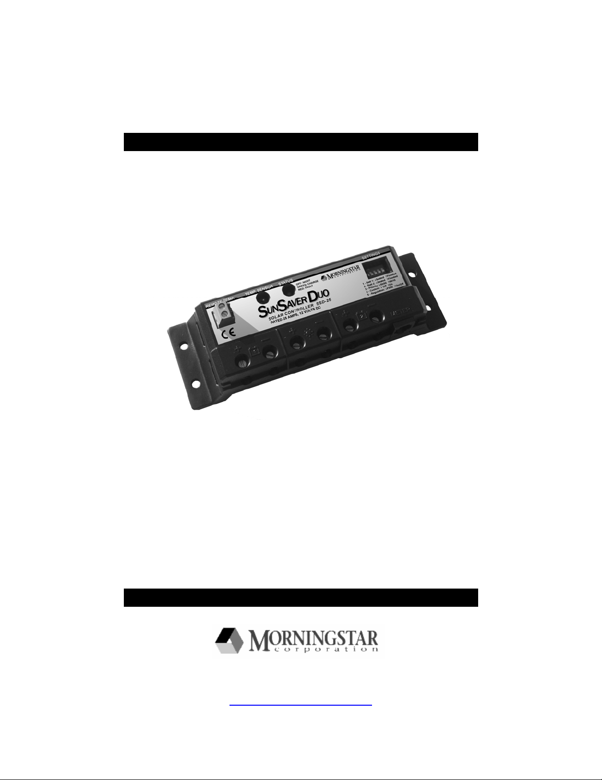
Dual Battery Charging Solar Controller
for RVs, Caravans, and Boats
….
……………………………….…………
Nominal Voltage 12 Volts
Rated Solar Current 25 Amps
1098 Washington Crossing Road
Washington Crossing, PA 18977 USA
www.morningstarcorp.com
Ratings
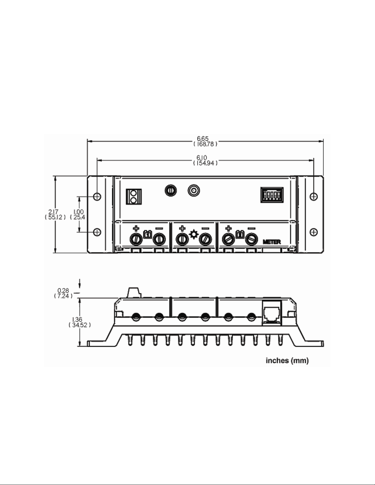
SUNSAVER DUO DIMENSIONS
2

Contents
1.0 Important Safety Information ................................................................................. 4
2.0 General Information ................................................................................................ 5
2.1 Overview.............................................................................................................. 5
2.2 Morningstar Accessories...................................................................................... 7
3.0 Installation ............................................................................................................... 8
3.1 General Installation Notes.................................................................................... 8
3.2 Adjusting DIP Switches........................................................................................ 9
3.3 Mounting ............................................................................................................ 11
3.4 Wiring................................................................................................................. 12
4.0 Operation ............................................................................................................... 18
4.1 LED Indications.................................................................................................. 18
4.2 Charging Information ......................................................................................... 19
4.3 Protections......................................................................................................... 20
4.4 Inspection and Maintenance .............................................................................. 21
5.0 Troubleshooting .................................................................................................... 22
5.1 Error Indications................................................................................................. 22
5.2 General Problems .............................................................................................. 22
6.0 Limited Warranty ................................................................................................... 24
7.0 Technical Specifications ...................................................................................... 25
3
1.0 Important Safety Information
SAVE THESE INSTRUCTIONS:
This manual contains important safety, installation and operating instructions for the
SunSaver Duo solar controller.
The following symbols are used throughout this manual to indicate potentially
dangerous conditions or important safety instructions.
WARNING: Indicates a potentially dangerous condition. Use extreme caution when
performing this task.
CAUTION: Indicates a critical procedure for safe and proper operation of the
controller.
NOTE: Indicates a procedure or function that is important for the safe and proper
operation of the controller.
General Safety Information
• Read all of the instructions and cautions in the manual before starting the
installation.
• There are no user serviceable parts inside the SunSaver Duo. Do not disassemble
or attempt to repair the controller.
• Disconnect all sources of power to the controller before installing or adjusting the
SunSaver Duo. Ensure that both batteries and the solar power have been
disconnected before opening the access cover.
• There are no fuses or disconnects in the SunSaver Duo. Power must be removed
externally.
• Do not allow water to enter the controller.
• Confirm that the power wires are tightened to avoid excessive heating from a loose
connection.
4

2.0 General Information
2.1 Overview
Thank you for selecting the SunSaver Duo solar charge controller. The SunSaver Duo
is an advanced PWM dual-battery charge controller for RV’s, caravans, boats, and other
installations that require simultaneous battery charging of two separate (isolated)
batteries. The controller features a solar input connection and two battery connections.
A Status LED indicates charging progress and controller operating state. Battery
charging and operating parameters are adjusted using five (5) Settings DIP Switches.
The SunSaver Duo also features self-diagnostics and electronic error protection.
Corrosion resistant power terminals and an epoxy-encapsulated circuit board provide
maximum environmental protection. The SunSaver Duo also provides connections for a
Remote Temperature Sensor (RTS) and Remote Meter (RM-1).
5
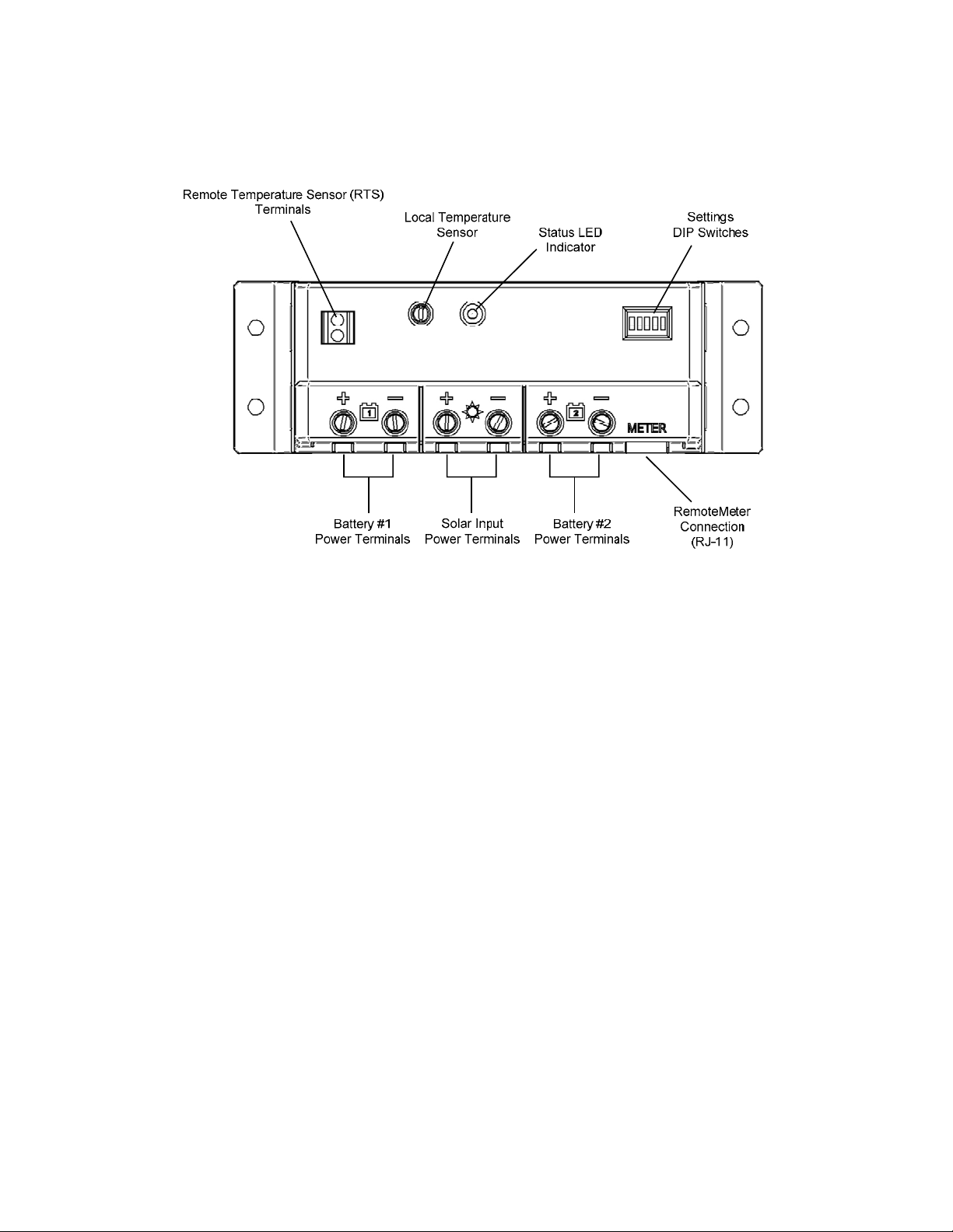
The major features of the SunSaver Duo are shown in figure 1 below. An explanation of
each feature is provided.
Figure 1. SunSaver Duo features
Remote Temperature Sensor (RTS) Terminals
A connection point for a Morningstar RTS (optional) to remotely monitor battery
temperature.
Local Temperature Sensor
Measures ambient temperature. Battery regulation is adjusted accordingly.
Status LED Indicator
Provides system status and error indication.
Settings DIP Switches
Adjustment switches that define the operating parameters of the SunSaver Duo.
Battery #1 Power Terminals
Power connections for battery #1.
Solar Input Power Terminals
Power connections for solar module(s).
Battery #2 Power Terminals
Power wire connections for battery #2.
Remote Meter Connection (RJ-11)
A communication port for the Morningstar Remote Meter.
6

2.2 Morningstar Accessories
Remote Temperature Sensor (Model: RTS)
The RTS measures battery temperature for accurate temperature compensation.
Use when the ambient battery temperature differs from the ambient controller
temperature by +/- 5 degrees C or more. An RTS can be attached to the
SunSaver Duo at any time. The SunSaver Duo will automatically use the RTS for
battery temperature compensation when installed. The standard cable length is
25 ft (7.6 m), and this can easily be extended to 100 ft (30 m) or longer.
Installation instructions are provided with the RTS.
Remote Meter (Model: RM-1)
The digital Remote Meter displays system operating information, error
indications, and self-diagnostic read-out. Information is displayed on a backlit 4digit custom LCD display. The large numerical display and icons are easy to read
and large buttons make navigating the meter menus easy. Additionally, a status
LED and three (3) battery SOC LEDs provide a quick reference to system
operation.
The meter can be mounted in a wall or on the surface of a wall in a frame. The
RM-1 is supplied with 32.8 ft (10.0 m) of cable, a mounting frame, and mounting
screws. The RM-1 connects to the MeterBus port on the SunSaver Duo.
PC MeterBus Adapter (Model: MSC)
The MSC converts the MeterBus RJ-11 electrical interface to a standard RS-232
interface which allows communication between the SunSaver Duo and a PC. The
MSC is required for programming custom charging setpoints and for logging
data. Visit Morningstar’s website for more information.
7

3.0 Installation
3.1 General Installation Notes
•
Read through the entire installation section before beginning installation.
•
Be very careful when working with batteries. Wear eye protection. Have fresh
water available to wash and clean any contact with battery acid.
•
Use insulated tools and avoid placing metal objects near the batteries.
•
Explosive battery gasses may be present during charging. Be certain there is
sufficient ventilation to release the gasses.
•
Do not install in locations where water can enter the controller.
•
Loose power connections and/or corroded wires can melt wire insulation, burn
surrounding materials, or even cause fire
cable clamps to secure cables in mobile applications.
• • Only charge lead-acid batteries.
Each of the two SunSaver Duo Battery connections may be wired to one battery
or a bank of batteries. The following instructions refer to a singular battery, but it
shall be implied that each battery connection can be made to either one battery
or a group of batteries wired in parallel to form a 12 volt battery bank.
. Ensure tight connections and use
8
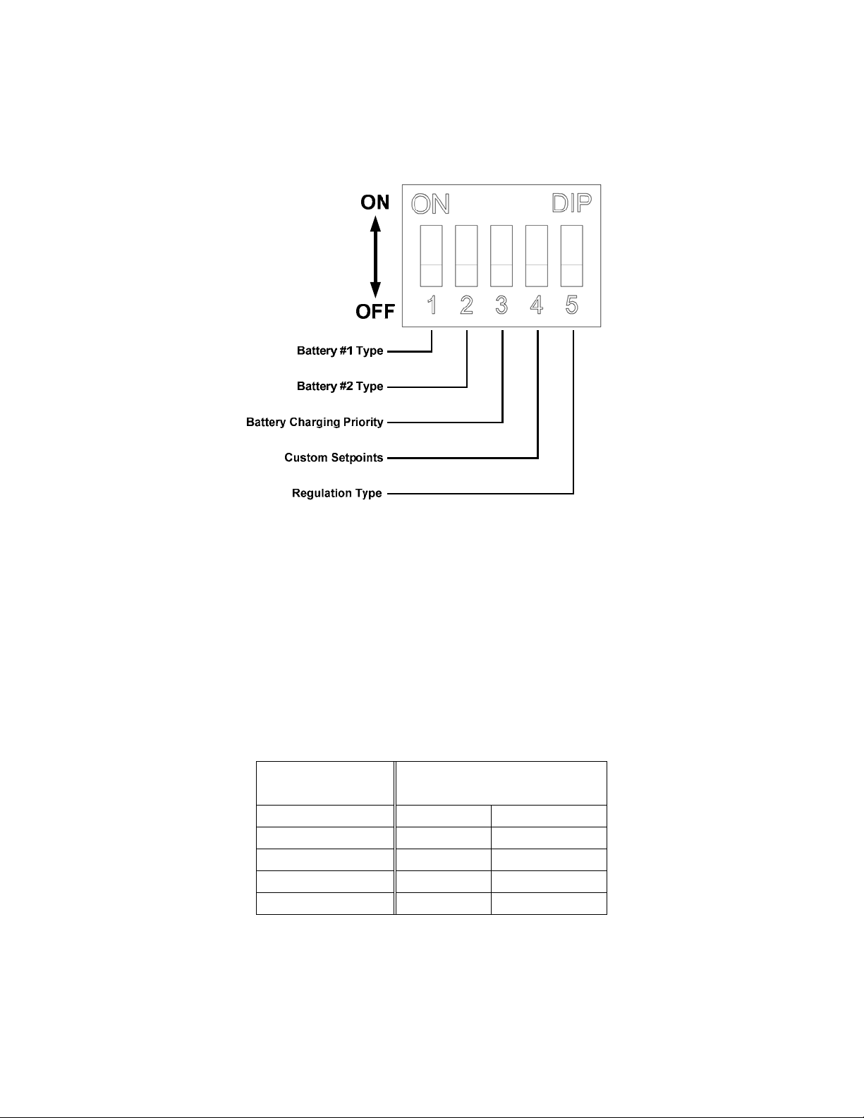
3.2 Adjusting DIP Switches
Figure 2. Setting DIP switch definitions
DIP Switches 1 & 2 – Battery Type Select
The SunSaver Duo charges both sealed and flooded lead-acid batteries per the
charging specifications in table 1 below. Sealed batteries are typically
maintenance-free batteries that do not require water. Flooded batteries have
removable caps that allow the addition of water when needed. DIP switches 1 &
2 select the battery type for Battery #1 and Battery #2 respectively. Choose the
correct battery type for each battery.
DIP Switch OFF: Sealed battery type (factory pre-set)
DIP Switch ON: Flooded battery type
Battery Type
Setpoint
Absorption Voltage 14.1 V 14.4 V
Float Voltage 13.7 V 13.7 V
Boost Voltage X 14.8 V
Boost Time X 2 hrs
Boost Interval X 28 days
Table 1. Standard battery charging programs
Sealed Flooded
DIP Switch 3 – Battery Charging Priority
Select the percentage of available charge current to each battery.
9
 Loading...