

Morningstar SunSaver, Sun Saver-10L Technical Documentation Manual
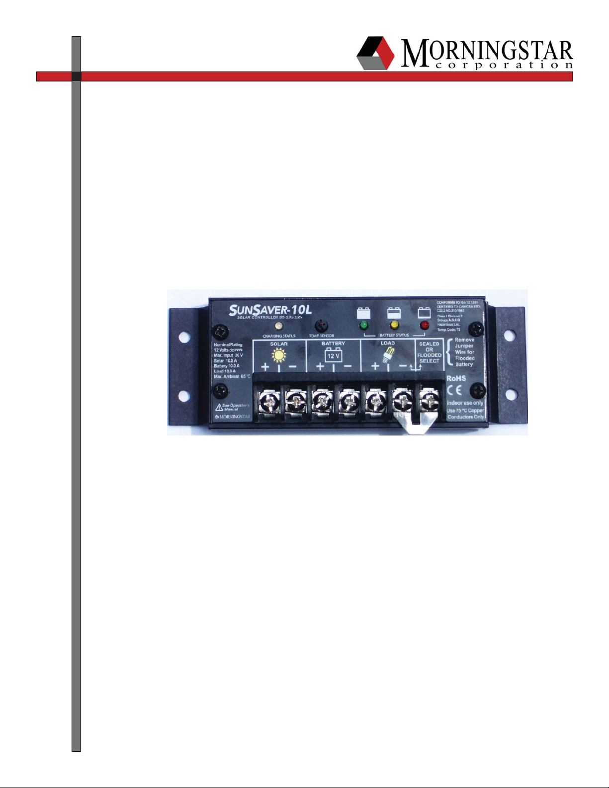
SunSaver
T e c h n i c a l D o c u m e n t a t i o n
Field Testing Procedures
Abstract:
The following test procedure was developed for use in fi eld conditions, where no external
power sources are available.
Technical Documentation
Note: Due to the fabrication process of the SunSaver controller, the exact damaged component may
not be evident. It may only be possible to determine if the unit is functioning properly. However, other factors may be apparent the will assist the technician in determining the cause of the
failure.
Recommended Tools:
• Digital multi-meter (frequency and duty cycle measurement are helpful)
• Phillips Screwdriver
• Flat Bladed Screwdriver
• 12V/2A load (type 1156 automotive lamp with socket works well)
• Short length(6 in) of 12AWG solid wire.
Caution:
!
The following outlined procedures assume a basic working knowledge of electrical circuits. Ex-
ercise the necessary precautions when dealing with live electrical circuits present in solar energy
systems
Testing Procedure
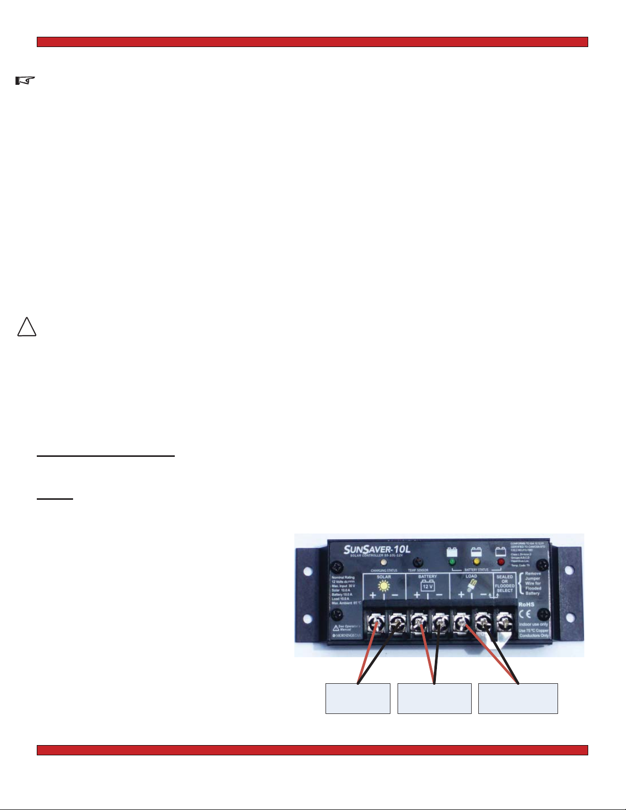
Step 1: No Power Applied to SunSaver
A) With no power applied to the SunSaver, check for short circuits to ground between the following terminals:
i) PV (+) and PV (-) terminals
ii) Battery (+) and Battery (-) terminals
iii) Load (+) and Load (-) terminals
i
PV (+) and PV (-)
Terminals
Battery Load
+-+-
ii
Batt (+) and Batt (-)
Terminals
Load (+) and Load (-)
iii
Terminals
page 2 of 5
 Loading...