

MORNINGSTAR SUNKEEPER Operation Manual
TM
S
UN
Solar Charge Controller
K
EEPER
Installation and Operation
Manual
….
Junction Box ( J-Box) Mounted Solar Controller
….
Models
……………………………….…………
SunKeeper-6 6A / 12V
SunKeeper-12 12A / 12V
1098 Washington Crossing Road
Washington Crossing, PA 18977 USA
www.morningstarcorp.com

Table of Contents
1.0 Safety Instructions 3
2.0 Installation 4
2.1 Installation Notes 4
2.2 Mounting to a J-box 6
2.3 Surface Mounting 9
3.0 LED Indications 12
4.0 Operation 13
4.1 Operator’s Tasks 13
4.2 Charging Algorithm 13
4.3 Charging Features 14
4.4 Protections 15
5.0 Inspection and Maintenance 16
6.0 Troubleshooting 17
6.1 Testing for Correct Operation 17
6.2 Flashing Red LED 19
6.3 Solid Red LED 20
7.0 Warranty 21
8.0 Technical Specifications 22
2

1.0 Safety Instructions
SAVE THESE INSTRUCTIONS – This manual
contains important instructions that should be followed
for proper installation and maintenance.
Read all of the instructions and cautions in the manual
before starting the installation.
WARNING – Be very careful when working with
batteries. Lead-acid batteries can generate explosive
gases, and short circuits can potentially draw hundreds
or thousands of amps from the battery.
Do not exceed the voltage or current ratings of the
controller. Use only with a 12V battery.
There are no user serviceable parts in the SunKeeper.
Do not disassemble or attempt to repair.
The negative system conductor should be properly
grounded per U.S. National Electric Code (NEC)
guidelines for most effective lightning protection.
3

2.0 Installation
2.1 Installation Notes
Hazardous Locations: The SunKeeper family of
charge controllers has been listed to UL1604 and CSA
22.2 No.213-M1987 for use in Class 1, Division 2,
Groups A, B, C and D hazardous locations. In order to
comply with the UL and CSA standards, the installation
should follow the requirements of the National
Electrical Code Article 501-4(b) and/or Canadian
Electrical Code Article 18-156 when installing a
SunKeeper in a Hazardous (Classified) Location.
System Wiring: Use copper wire only. Power
conductors should be joined or spliced using insulated
butt splice solderless crimp connectors or by brazing,
welding, or soldering wire ends. If soldered, the
spliced joint should be mechanically and electrically
secure before soldering. All splices and joints should
be covered with insulation equivalent to that of the
conductors.
System Fusing: The battery positive lead should be
fused no further than 12 inches (305 mm) from the
battery.
SK-6 8A fuse
SK-12 16A fuse
4

Temperature Compensation Select: The SunKeeper
has three temperature compensation options. The blue
Temperature Compensation Loop can be configured
for the following temperature compensation options:
♦ Loop not cut: Internal temperature sensor used
for temperature compensation (factory
default).
♦ Loop cut, left open: No temperature
compensation. Insulate/cap loose ends.
♦ Loop cut, connected to RTS: Remote
Temperature Sensor (RTS)* used for
temperature compensation.
* The RTS is an optional Morningstar accessory
purchased separately. Only use a Morningstar RTS
with the SunKeeper.
Cover the Solar Module(s): Keep the solar module
out of sunlight or covered with an opaque sheet until
installation is complete.
SunKeeper Wire Lead Definitions:
Solar + Yellow
Battery + Red
Common Negative Black
RTS Option Blue Loop
NOTE: The RTS connection has no polarity. The red
and black RTS wires may be wired to either of the blue
Temperature Compensation Loop leads.
5
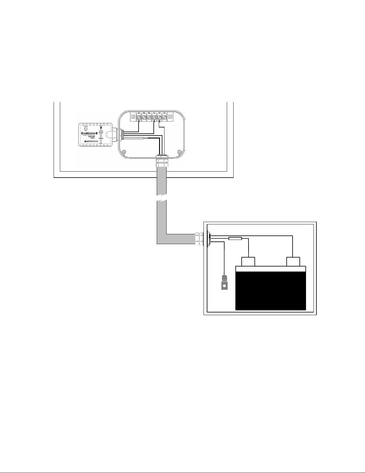
2.2 Mounting to a J-box
NOTE: Complete steps 1 through 7 before mounting
the solar module.
SOLAR MODULE
( BOTTOM VIEW )
J-BOX
CONDUIT
FUSE
+
RTS
BATTERY
Figure 1. Typical System
1. Remove the solar module j-box cover (refer to
solar module documentation if necessary).
-
2. Unscrew the SunKeeper locknut and remove the
plastic mounting feet. Store the mounting feet in a
safe place. They are not needed when mounting to
a j-box.
6

3. On the solar module j-box: choose knockouts or
drill 7/8 inches (22.2 mm) holes for the SunKeeper
and ½” conduit entry into the j-box. If drilling holes,
choose locations that will allow easy wiring access
to the solar module power terminals and easy exit
into the ½” conduit.
4. Insert the SunKeeper leads into the chosen
knockout or drilled hole.
5. Thread the SunKeeper leads through the locknut
and slide the locknut down to meet the threaded
neck of the SunKeeper.
6. Screw the locknut hand-tight onto the threaded
neck of the SunKeeper. The rubber o-ring should
seat firmly against the j-box outside wall around
the perimeter of the hole forming a watertight seal.
When satisfied that a good seal is made, fully
tighten the locknut.
7. Pull 2 cables for battery positive and battery
negative as well as the RTS sensor lead (if using
an RTS) through the conduit.
8. On the SunKeeper: select the temperature
compensation configuration required (Refer to
section 2.1:
Installation Notes -Temperature
Compensation Select
) .
If using an RTS:
a. Cut the blue Temperature Compensation Loop
on the SunKeeper in the middle of the loop
creating two (2) equal length wire leads.
7
 Loading...