

Morningstar SNMP User Manual
Morningstar
Product Connectivity Manual
Networking & Communications
4 December 2019
MORNINGSTAR
Corporation
www.morningstarcorp.com

8.0 E-mail Alerts / SNMP Traps / SNMP Polling
!
1.0 Introduction
1.1 Communications Protocols
1.2 Communications Interfaces
1.3 RS-232 vs. USB
2.0 Networking Hardware
2.1 Morningstar Equipment
2.2 Other Equipment
3.0 MeterBus
TM
Networks
3.1 Overview
3.2 Networking Rules
3.3 Example Networks
3.4 Setup Your MeterBus
TM
Network
Contents
9.0 Data Logging
10.0 Network Security
11.0 Troubleshooting & Misc.
Appendix I - TSMPPT & EMC-1 Networking
I. Introduction
II. Connect to LAN
III. Remote Access
IV. Multi-Controller Networking
V. Additional Info
Appendix II - Advanced System Example
General Safety Information:
4.0 MODBUS™ Networks
4.1 Overview
4.2 Local Connections
4.3 Remote Connections
5.0 MSView™
5.1 Overview
5.2 Installation
5.3 Establishing A Connection
5.4 Creating New Displays
5.5 Setup Wizards
6.0 MSLoad™
6.1 OverView
• Only minimal voltages/currents are present in communications circuits,
however, it is always necessary to exercise caution when working with
electronic circuits. Please observe caution while performing any installation/
maintenance outlined in this document.
• Do not allow any electronic components to be exposed to water at any time.
• Read installation and conguration procedures thoroughly before proceeding
with physical connections.
The following symbols are used throughout this document to indicate potentially
dangerous conditions or mark important safety instructions.
WARNING: Indicates a potentially dangerous condition.
Use extreme caution when performing this task.
CAUTION: Indicates a critical procedure for safe and
proper operation of the components in use.
6.1 Uploading Firmware
6.1 Firmware Upgrades Without A DB-9 (RS-232) Connection
7.0 Web site Hosting via HTTP
2
Contents
NOTE: Indicates a procedure or function that is important
for the safe and proper operation of the system.
3Morningstar Product Connectivity Manual

1.0 Introduction
!
Thank you for choosing Morningstar for your PV control system needs. Morningstar prod-
ucts oer a wide range of networking, logging, data transfer, and custom setting capabilities. Please review this document carefully and become familiar with all the networking/
communication options Morningstar products have to oer.
1.1 Communications Protocols
Various protocols are used by Morningstar products to either communicate between Morningstar
devices, or with a PC/other 3rd party hardware. A brief description of these protocols follow:
IMPORTANT: Morningstar products are MODBUS™
RTU devices.
For more information into the capabilities of MODBUSTM, please refer to Section 4.
1.1.3 MODBUS TCP/IP
The MODBUSTM protocol can also be used over Internet Protocol (IP) via an Ethernet
connection. MODBUS
however, it is embedded in data packets characteristic of IP.
MODBUS TCP/IPTM uses an Ethernet (RJ-45) connection and is supported by all Morningstar
products with an Ethernet port. It allows the user to connect to the Ethernet enabled unit using
the MSViewTM software package and view real-time system data, log system data, and program
custom charging setpoints.
TM
TM
data over IP is identical to MODBUSTM data over serial RS-232,
1.1.1 Morningstar MeterBus
MeterBusTM Protocol is Morningstar’s proprietary messaging structure for communication between Morningstar products. This protocol is used for communications between controllers and
meters, controllers and Relay Drivers, and for other inter-product data transfer.
Morningstar products supporting this protocol feature RJ-11 ports. Physical connections between
MeterBusTM devices are made using standard 4 or 6 conductor phone cords with RJ-11 connectors. MeterBus
setup and maintain.
Meter Hubs are used to network MeterBusTM capable devices. Each network device is assigned a
unique MeterBus™ ID. In these networks, some devices supply power to the network, while others receive power from the network.
For more information into the capabilities of MeterBusTM and how to setup a MeterBusTM network,
please refer to Section 3.
TM
networks have a 15 device capability, a simple RJ-11 interface, and are easy to
TM
1.1.2 MODBUS
MODBUSTM is an open and license-free protocol that is widely regarded as the de facto standard
in the industrial automation industry. There is an abundance of software and equipment available
that directly support MODBUSTM. Additionally, sample source code for a variety of platforms is
readily available online. Morningstar’s free MSView™ PC software uses MODBUSTM for all communications.
MODBUSTM does not rely on any one physical communication interface; it works the same on all
physical interfaces. Each device is congured to be a master or a slave. Masters always ‘poll’ or
start conversations on the network and either slaves or other masters can respond. Two modes
of MODBUSTM transmission exist, ASCII and Remote Terminal Unit (RTU).
Morningstar products without an Ethernet port (but with another communications port) require the
EMC-1 Ethernet to MeterBus™ Adapter or a MODBUS
a bridge between MODBUS IPTM and serial MODBUSTM in order to be connected to an Ethernet
network. See Sections 2.1.4 and 2.2.10.
TM
Ethernet to Serial converter serving as
1.1.4 HTTP
HyperText Transfer Protocol is the most common communications protocol used for transmitting
data over the internet. Ethernet capable Morningstar controllers feature HTTP compatibility,
enabling it to host web pages that display controller settings, real-time system data, logged
historical data, and system status.
1.1.5 SMTP
Simple Mail Transfer Protocol (SMTP) is used by Ethernet enabled Morningstar controllers
to deliver e-mail alerts and regular status updates of the system. See Section 8 for more
information on the ability to provide e-mail/sms alerts via SMTP.
1.1.6 SNMP
Simple Network Management Protocol (SNMP) is an internet standard protocol that is used to
manage and monitor devices on an IP network. It is typically supported by devices found in IT
infrastructures, such as servers, modems, routers, printers, workstations, and other network
components.
Using the dened communication standards and management topology, SNMP allows for a
simple and convenient way to view and modify the status of critical system components on a
private Local Area Network (LAN) or across a Wide Area Network (WAN), if so desired. See
Section 8 for more information on how SNMP is implemented with Morningstar controllers.
4
Introduction
5Morningstar Product Connectivity Manual

1.2 Communications Interfaces
The following table outlines the various communications interfaces found on Morningstar products. (Each dot represents one interface.)
Product RJ-11 RS-232 EIA-485 USB Ethernet
some of the problems with USB and why RS-232 was chosen to be the Morningstar standard:
RS-232 is a more universal standard
• USB cannot go long distances (maximum range without repeaters/hubs is 5 meters)
• USB requires more expensive hardware
• USB requires more software / RS-232 requires no driver support
• USB isn’t easily opto-isolated (opto-isolation helps protect devices from transient power
surges)
• USB is less popular as an industrial standard
PC MeterBus™ Adapter (MSC)
RS-232 / RS-485 Adapter (RSC-1)
USB MeterBus™ Adapter (UMC-1)
Ethernet MeterBus™ Converter (EMC-1)
Meter Hub (HUB-1)
Relay Driver (RD-1)
Remote Meter (RM-1)
TriStar Meter (TS-M-2)
TriStar Remote Meter (TS-RM-2)
TriStar Meter 600V (TS-M-2-600V)
SunSaver Duo (SSD-25)
SunSaver MPPT (SS-MPPT-15L)
ProStar (PS-xx..) (3rd Generation only)
ProStar MPPT (PS-MPPT-xx..)
TriStar (TS-xx)
TriStar MPPT 150V (TS-MPPT-xx)
● ●
● ●
● ●
● ●* ●
● ● ● ● ● ●
● ● ●
●
● ●
● ●
● ●
●
●
●
●
● ●
● ●** ●**, *** ●
Ethernet has emerged as the more useful interface than USB, therefore, many new Morningstar
products will have a built-in Ethernet interface.
As a convenience for those who are using a PC or laptop that does not include a RS-232 port
Morningstar has introduced the UMC-1 USB MeterBusTM Adapter (Section 2.1.3). There are
also 3rd party USB to RS-232 devices available on the market (Section 2.2.8)
TriStar MPPT 600V (TS-MPPT-60-600V-48...)
SureSine (SI-300-xxxV)
Table 1. Morningstar Device Communication Interfaces
* RS-232 serial connection required for products that include an RS-232 port. The EMC-1 included Ycable is required to draw power from the RJ-11 port while communicating via the RS-232 port. An EMC-1
connection to RD-1 requires a MeterBus™ connection
in section 3.2.2.
** RS-232 and EIA-485 connections share the same internal hardware, therefore, only one interface can
be used at a given time.
*** EIA-485 and Ethernet ports are only available for 60A model (TS-MPPT-60) of the TriStar MPPT 150V
models. The TS-MPPT-30 and TS-MPPT-40 models do not include the EAI-485 or Ethernet ports.
● ●** ●** ●
●
from a device that can supply power. See Table 2
1.3 RS-232 vs. USB
Many Morningstar products use the RS-232 interface as standard for communication with a PC.
Some have inquired as to why a USB interface was not used instead. The following describes
6
Introduction
7Morningstar Product Connectivity Manual
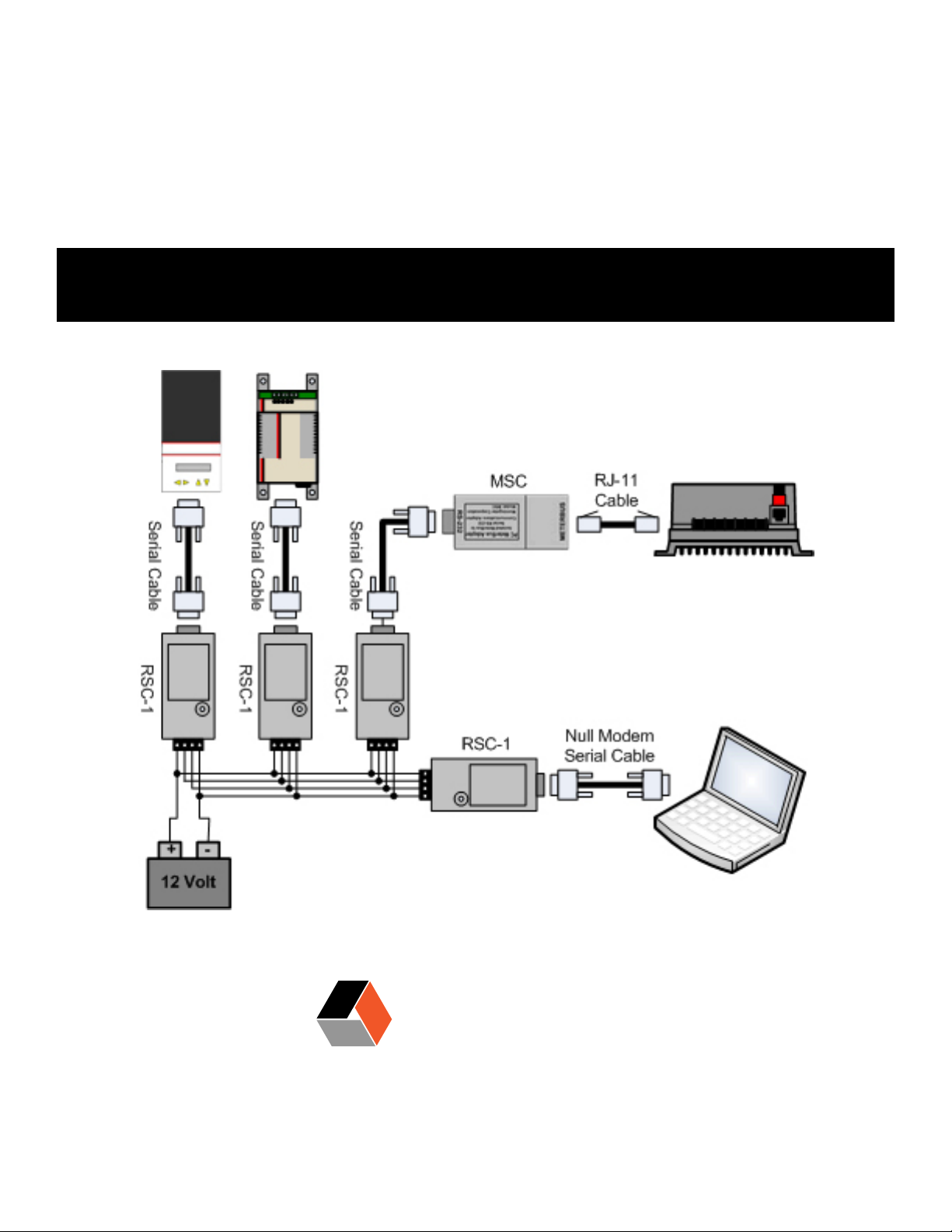
The RSC-1 adapter provides the ability to network serial devices over an EIA-485 bus using the
!
Networking Hardware2.0
MODBUS
through serial cable is used to connect a Morningstar device to the RSC-1.
TM
protocol. A null modem cable is used to connect a PC to the RSC-1, while a straight-
There are many pieces of networking hardware. The following is a description of the most common hardware used to network Morningstar devices.
2.1 Morningstar Equipment
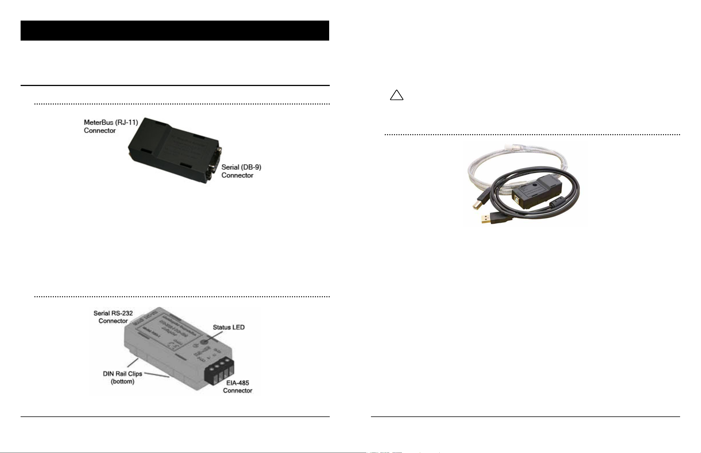
2.1.1 PC MeterBus™ Adapter (MSC)
Figure 1. Morningstar PC MeterBus™ Adapter (model: MSC)
The PC MeterbusTM Adapter (model: MSC) converts the Morningstar MeterBusTM RJ-11 electrical
interface to a standard RS-232 interface which allows MODBUSTM communication between a PC
and a Morningstar charge controller or inverter**. Controllers with only an RJ-11 port require the
MSC to program custom charging setpoints or log data using Morningstar’s MSViewTM PC software. The MSC can also be used with any 3rd party MODBUSTM capable hardware to communicate with the Morningstar unit.
** controllers or inverters with a MeterBusTM connection that do not have a serial port or other communications port
2.1.2 RS-232 / EIA-485 Adapter (RSC-1)
The RSC-1 requires an external power source. Input voltage to the adapter should be between
8-16V, therefore, it may be powered by a 12 Volt battery. Use a DC-DC converter for 24V, 36V,
and 48V system batteries.
CAUTION: Tapping o individual batteries in a bank can
cause an imbalanced battery bank. Always use a DC-DC
converter if the nominal system voltage is greater than 12V.
2.1.3 USB MeterBus™ Adapter (UMC-1)
Figure 3. Morningstar Meter Hub (model:UMC-1)
The USB MeterBus™ Adapter (model: UMC-1) converts the Morningstar MeterBusTM RJ-11
electrical interface to a standard USB 2.0 interface which allows MODBUSTM communication
between a PC and a Morningstar charge controller or inverter**. Controllers with only an RJ-11
port can use the UMC-1 to program custom charging setpoints, log data using Morningstar’s MS-
TM
View
UMC-1 can also be used with any 3rd party MODBUS
the Morningstar unit.
PC software or perform Firmware updates with Morningstar’s MSLoadTM Software. The
TM
capable hardware to communicate with
** controllers or inverters with a MeterBusTM connection that do not have a serial port or other communications port
Figure 2. Morningstar RS-232 / RS-485 Adapter (model:RSC-1)
8
Networking Hardware
9Morningstar Product Connectivity Manual

2.1.4 Ethernet MeterBus™ Converter (EMC-1)
Figure 4. Morningstar Ethernet MeterBus™ Converter (model: EMC-1)
2.1.5 Meter Hub (HUB-1)
The EMC-1 is an Ethernet to MeterbusTM converter that creates a Serial-to-Ethernet connection
to a Morningstar charge controller or inverter (Morningstar Device). The connected device needs
to have a MeterBus™ (RJ-11) port.
The EMC-1 acts as an Ethernet gateway that serves MODBUS IP, local Web pages, SNMP, and
for future use, Web Monitoring Services. Ethernet connectivity allows users to remotely collect
information about their o-grid PV system. Ethernet networks also include Local Area Networks
(LANs) and Internet communications.
The EMC-1 supports the following communication capabilities with a Morningstar Device:
• Morningstar LiveViewTM Internet Web monitoring and Network settings congurations.
• Monitoring, logging and custom programming using Morningstar MSViewTM PC software
• (future use) Cloud-based Web Monitoring
• SNMP polling of dynamic solar values through 3rd-party Network Management Software (NMS)
Figure 5. Morningstar Meter Hub (model:HUB-1)
The Meter Hub allows for easy scalability of a MeterBusTM network by providing ve extra RJ-11
MeterBus
& B. Each draws operating power from the device connected to the Port. Up to four Meter Hubs
can be linked on the same MeterBus
ing proper use of Meter Hubs.
TM
ports. Ports 1-4 are electrically isolated from Power Output and Power Input Ports A
TM
network. Refer to Section 3.2 for more information regard-
2.2 Other Equipment
In addition to Morningstar equipment, other 3rd party networking supplies will usually be needed.
The following is a description of products which may be needed for proper networking. These
products will be mentioned throughout this manual; please take the time to familiarize yourself
with them.
For some, a specic company/product recommendation is made. Recommendations made are
only a guideline for the user. Morningstar makes no guarantee that these products will
interface properly with Morningstar units. Please do all necessary research into compat-
ibility before making a purchase.
10
Networking Hardware
2.2.1 Serial (DB-25) / Serial (DB-9) Adapter
There are two dierent types of serial connectors. One has 25 pins and the other (found on
Morningstar devices) has 9 pins. Adapters are available to convert 25 pin serial to 9 pin serial.
One may be necessary, for example, if your computer has a 25 pin serial connection and you
want to directly connect to a TriStar with a 9 pin connection. These adapters usually do not come
attached to the end of a serial cable; a cable is needed in addition to the adapter.
11Morningstar Product Connectivity Manual
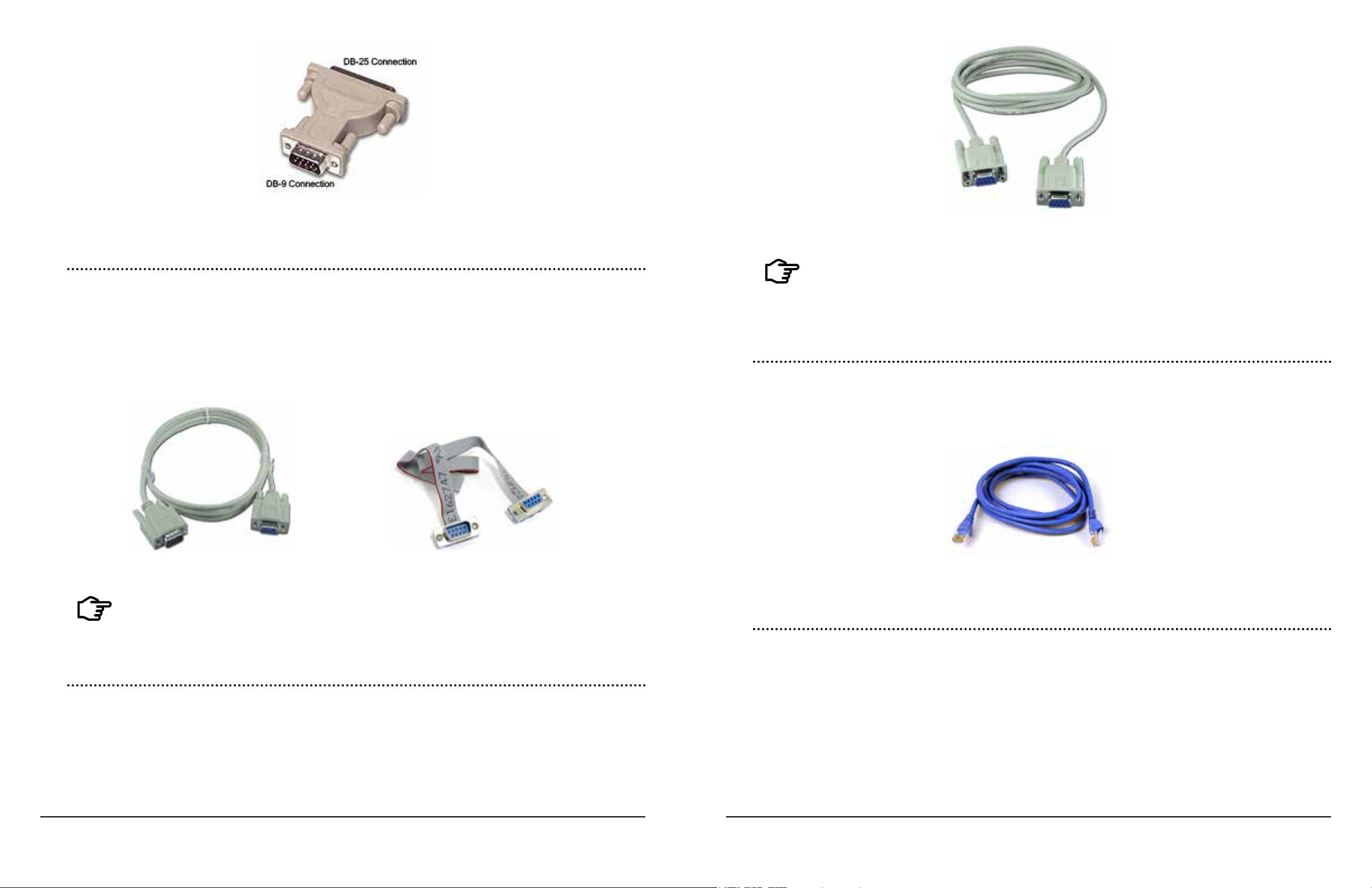
Figure 6. DB-25 to DB-9 Adapter
Figure 8. Null Modem Serial Cable
2.2.2 Straight-Through Serial Cable
Straight-through serial cables connect a Data Terminal Equipment (DTE) device to a Data Communications Equipment (DCE) device by matching Tx pins, Rx pins, CTS pins, and RTS pins
between devices, thus the name straight-through cable. Both ends of the cable terminate in DB-9
connectors. These can either be regular-style (cylindrical) or ribbon cable (at); either are suitable for use. When using a TriStar controller, a ribbon-style cable is needed for proper t under
the cover lid; a regular-style cable will not t. www.blackbox.com has low-prole ribbon cables for
purchase.
Figure 7a. Regular-style serial cable Figure 7b. Ribbon-style serial cable
NOTE: Both straight-through and null modem serial cables
will vary in color, length, and male/female end connections.
They may look identical on the outside, but internally they
are dierent.
2.2.4 Ethernet Cable
Category 5 or 5e cables (Cat5) have four twisted pairs of conductors terminating in an RJ-45
connector. The conductors can either be solid or stranded. Solid conductor is less expensive,
however, it does not provide the exibility and resiliency of stranded conductor. These cables are
most commonly used in LAN/WAN 100Mbit/s networks.
Figure 9. Standard Ethernet Cable
NOTE: Male/female end connections will vary. Please be
sure you purchase a cable with the proper connectors to
attach your devices.
2.2.3 Null Modem (Crossover) Cable
A null modem serial cable allows two DTE devices to communicate directly without a DCE
device, such as a modem. The null modem cable connects the Rx (receive) pins to opposing Tx
(transmit) pins and Clear-to-Send (CTS) pins to their opposing Request-to-Send (RTS) pins. Both
ends of the cable terminate in DB-9 connectors.
12
Networking Hardware
2.2.5 Ethernet Crossover Cable
Similar to a null modem cable, an Ethernet crossover cable allows two devices that are normally
connected through a hub or a router to communicate directly. When these devices are connected
through a hub or router, the crossover is done internally, making a crossover cable unnecessary.
13Morningstar Product Connectivity Manual

Figure 10. Ethernet Crossover Cable
!
NOTE: Both standard and crossover Ethernet cables will
vary in color and length. They may look identical on the
outside, but internally they are dierent.
Figure 12. Serial RS-232 / EIA-485 Converter
2.2.6 RJ-11 Cable
RJ-11 cable is the standard cable used in telephone wiring. The wire must be either 4 or 6 (commonly referred to as RJ-12) conductor and terminate in RJ-11 connectors. Morningstar products
that require an RJ-11 cable will ship with one in-box. The provided cable should always be used.
Figure 11. RJ-11 (telephone) Cable
2.2.7 Serial / EIA-485 Converter (3rd Party)
As an alternative to the Morningstar RSC-1, other companies oer Serial / EIA-485 converters.
These converters, like the RSC-1 provide the ability to network serial devices over an EIA-485
TM
bus using the MODBUS
ered, opto-isolated or non-isolated. For the converter to work properly with Morningstar products,
it must be externally powered and non-isolated. This allows the converter to supply the necessary power to opto-isolated serial ports. Note: The Morningstar RSC-1 adapter is highly recom-
mended for this application. It has been specically designed to work with Morningstar products.
Some 3rd party adapters have been known to either cause problems on the network, or need
minor pin modications to work properly.
protocol. Converters can either be port powered or externally pow-
Recommended: Morningstar’s RS-232 / EIA-485 Adapter (RSC-1) (See Subsection 2.1.2)
2.2.8 USB / Serial Adapter Cable
A USB / Serial adapter cable will convert a USB connection on your PC to a DB-9 serial connection, compatible with Morningstar devices. Note: Most of these adapter cables come with drivers
which must be installed to created a Virtual COM port (VCOM). This allows the computer to view
a USB port as a serial port. More can be found on VCOMs in Subsection 5.3.1. It has been re-
ported that some USB to Serial adapters will not work with either the MSC or our control-
lers. This is usually due to the adapter output voltage being below the RS-232 electrical
specication. Section 11 Troubleshooting explains this further.
Note: For controllers which do not include an RS-232 port the UMC-1 USB to MeterBus™
Adapter is highly recommended and a more practical solution than using the MSC PC MeterBus™ Adapter with a 3rd party USB / Serial Adapter.
Figure 13. Tripp Lite USB / Serial DB-9 Adapter
Recommended: Tripp Lite U209-000-R (shown above)
2.2.9 USB Hub
CAUTION: Example: If a converter needs 12V external
power in a 24V system, a DC-DC converter should be used.
Tapping o individual batteries can cause an imbalanced
battery bank.
two types of hubs, bus-powered and self-powered. Bus-powered hubs draw all their power from
the PC’s USB port and require devices connected to them to share this power. This often limits
the number and types of USB devices which can be connected to the hub. Self-powered, however, uses an external power source to supply full power to every port on the hub.
A USB hub allows multiple USB devices to use the same built-in USB port on your PC. There are
14
Networking Hardware
15Morningstar Product Connectivity Manual

Figure 14. Aaxeon USB Hub
Recommended: Aaxeon USB-HUB4K (shown above)
2.2.10 Ethernet / Serial Converter (supporting MODBUS
TM
)
As an alternative to the Morningstar EMC-1 other companies oer Ethernet / Serial converters which can allow the Ethernet port on your PC, router, or hub to connect to the DB-9 serial
port on Morningstar devices. (Often these converters will have an EIA-485 connection for use
with an EIA-485 network.) It provides a gateway between MODBUS IPTM and MODBUSTM serial
networks. This converter can allow for direct PC to controller/inverter connection, or connection
via LAN/WAN/Internet. Software usually comes with the converter and allows you to assign it an
appropriate IP address. Important: The converter must be capable of MODBUS TCP/IPTM
support.
Note: The Morningstar EMC-1 Ethernet MeterBus™ Converter is highly recommended for this
application. It has been specically designed to work with Morningstar products without requiring an MSC adapter. The EMC-1 also provides Live View HTML pages which are not available
through 3rd party products. Some 3rd party adapters have been known to either cause problems
on the network, or need minor pin modications to work properly.
2.2.11 Ethernet Router
Ethernet routers allow you to establish a LAN, which can then be connected to the Internet.
Information sent from a PC or device will have a destination address. It travels to the router,
where the router looks up the destination address and forwards it to the appropriate PC or device
on the local network. This equipment can be used to connect multiple controllers and a PC over a
network and allow them to communicate using the MODBUS IP
Figure 16. RuggedCom Ethernet Router
Recommended: RuggedCom RuggedRouter RX1000 (shown above)
NOTE: Routers vary greatly in cost. The RuggedRouter
RX1000 is a high-end industrial router. If a less expensive,
non-industrial router is desired, Linksys provides reliable
alternatives.
2.2.12 Cellular Modem/ Cellular Router (supporting MODBUS
Wireless cellular modems and routers can connect through an existing cell network. Several mobile standards exist. Global System for Mobile communications (GSM) is used extensively on the
global cell market. Newer standards are also available such as UMTS, CDMA or EV-DO. Verify
your cellular service provider uses a mobile standard compatible with the cellular modem you
purchase. Important: This equipment must be MODBUSTM compatible.
TM
protocol.
TM
)
Figure 15a. Moxa Ethernet / Serial Converter (A) Figure 15b. B&B Elec. Converter (B)
Recommended: (A) MOXA MGate MB3180/3280/3480 (please refer to Section 11) or
(B) B&B Electronics MES1A
16
Networking Hardware
Figure 17a. Moxa Cellular Modem (A) Figure 17b. Digi Cellular Router
Recommended: (A) MOXA OnCell Quad-band GSM/GPRS 850/900/1800/1900 MHz
(B) Digi Connect WAN Family of products (one model shown above)
NOTE: Please consult your wireless data provider
for information regarding if/how your cellular modem
connection will suit your needs and applicable fees.
17Morningstar Product Connectivity Manual
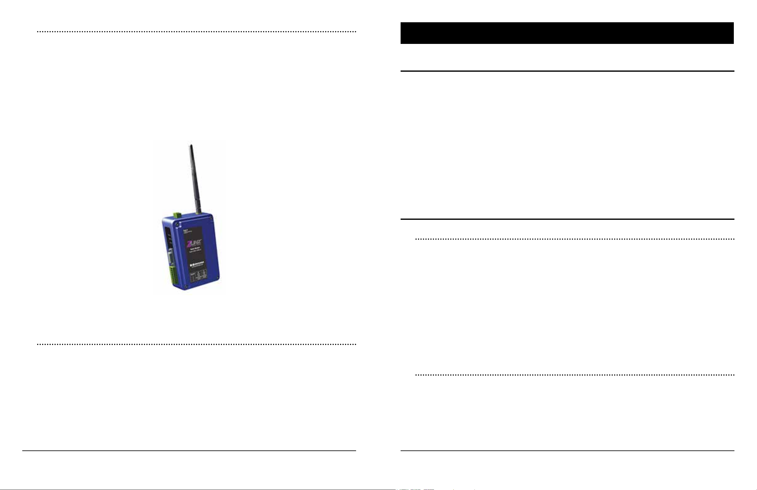
2.2.13 Point-to-Point Radio (supporting MODBUS
These radio systems are used to connect remotely to a device 10-25km away in the eld. This
type of connection requires a base radio at the PC and a eld radio at the device site. Data is
transmitted wirelessly over the connection without the need for external services or fees. These
devices often operate in the ISM band so unlicensed operations are typically permitted. Some
systems can have multiple eld units, however, the base radio can only communicate with them
one at a time.
Advanced security encryption is recommended when using these devices. Data transmitted wirelessly is much easier to intercept than data over a wired connection. Proper encryption ensures
your data is protected.
Important: This equipment must be MODBUS
TM
compatible.
TM
)
MeterBus
Networking3.0
3.1 Overview
The MeterBusTM Protocol is Morningstar’s proprietary messaging structure for communication
between Morningstar products. This protocol is used for communications between controllers
or inverters and meters, controllers and Relay Drivers, and possibly for future inter-product data
transfer purposes.
Morningstar products supporting this protocol feature RJ-11 ports.
Setup a MeterBusTM network to:
• display net system data for multiple controller systems**
• communicate with a TriStar Meter 2 or TriStar Remote Meter 2 ***
• communicate with a Relay Driver
**A Morningstar MeterBus™ Hub (HUB-1) and TriStar Digital Meter 2 (TS-M-2) or TriStar Remote Meter 2 (TS-RM-2) are required,
***TriStar Meters are only compatible with TriStar and TriStar MPPT controllers at the time of this publication.
TM
Figure 18. B&B Electronics P-to-P Radio Modem
Recommended: B&B Elec. Zlinx Industrial Radio Modem ZP24D-192RM-MR (shown above)
2.2.14 Programmable Logic Controller (PLC) - MODBUS
Programmable Logic Controllers can be used as master devices on EIA-485 networks. When
multiple controllers are connected over an EIA-485 bus, they are not able to communicate with
each other. However, a master device, such as a PLC or PC, is able to poll each controller and
retrieve information.
Morningstar controllers are MODBUSTM Remote Terminal Unit (RTU) slave devices and can
be polled by RTUs and PLCs with MODBUSTM capability. SCADA (System Control And Data
Acquisition) systems often use PLCs to poll RTU devices for data.
PLCs vary greatly in their features and pricing, however, you must be sure the PLC is
MODBUSTM compatible for it to communicate with Morningstar products.
TM
supported
3.2 Networking Rules
3.2.1 General
• Up to four Meter Hubs can be linked together, accommodating a maximum of 15 Morningstar devices on a single MeterBusTM network.
• A maximum of two meters (of any model) are allowed on a single MeterBusTM network.
• Each device in the network must be programmed with a unique MeterBusTM ID.
• Ports 1-4 on the Meter Hub provide no output power and are isolated from all other ports.
• Ports A & B are not isolated from each other.
• A TriStar Meter 2 is required for MeterBusTM network data display.
• The ProStar and ProStar MPPT built-in meter will continue to function on a MeterBusTM
network but will not display network data.
• The RM-1 cannot be used on a MeterBusTM network.
3.2.2 Power Management
The Meter Hub electrically isolates devices that supply power to the MeterBusTM, preventing
grounding problems.
Table 2 below lists all Morningstar Devices that can be networked using the Meter Hub. Table 2
is divided into two columns. Column A lists all devices that supply power to the MeterBusTM Network. All devices listed in column B require power from the MeterBusTM Network to operate. It
is important to understand the power requirements of each device connected to a MeterBusTM
network. Devices that require power from the network must be connected to devices that supply
power.
18
Networking Hardware
19Morningstar Product Connectivity Manual
(A) Supplies Power (B) Requires Power
SunSaver Duo Remote Meter (RM-1)
SunSaver MPPT TriStar Digital Meter 2 (TS-M-2)
ProStar Gen 3 TriStar Remote Meter 2 (TS-RM-2)
ProStar MPPT Relay Driver
TriStar MeterBus™ Adapters & Convert-
TriStar MPPT (150V & 600V)
SureSine
Table 2. Morningstar Device MeterBusTM Power Specications
• One device from Table 2. Column A must be connected to Input Power Port B of the Meter
Hub. Ports A and B are not isolated from each other, therefore, when Input Power Port B is
energized, Output Power Port A provides power to its device.
ers for MODBUS™/MeterBus™
(see section 4.3.5)
Figure 19. Morningstar MeterBusTM Small Network Diagram
3.3.2 Example #2 - Medium-Sized Network
• To link multiple hubs, Output Power Port A is connected to Input Power Port B on the next
hub, thereby providing power.
• A maximum of three devices can be powered o a single device from Column A. The
Multiple-Hub diagram in Figure 22 illustrates this.
• Only one device from Table 2, column A may be connected to each port on the Meter Hub.
• Table 2, Column B devices cannot be the only device connected to ports 1-4 (these ports
do not provide output power).
• To supply power to a device from Column B, you must connect a device from Column A to
the device from Column B, and then connect that device (B) to a port on the Meter Hub.
Example Network #2 shows how to correctly achieve this.
3.3 Example Networks
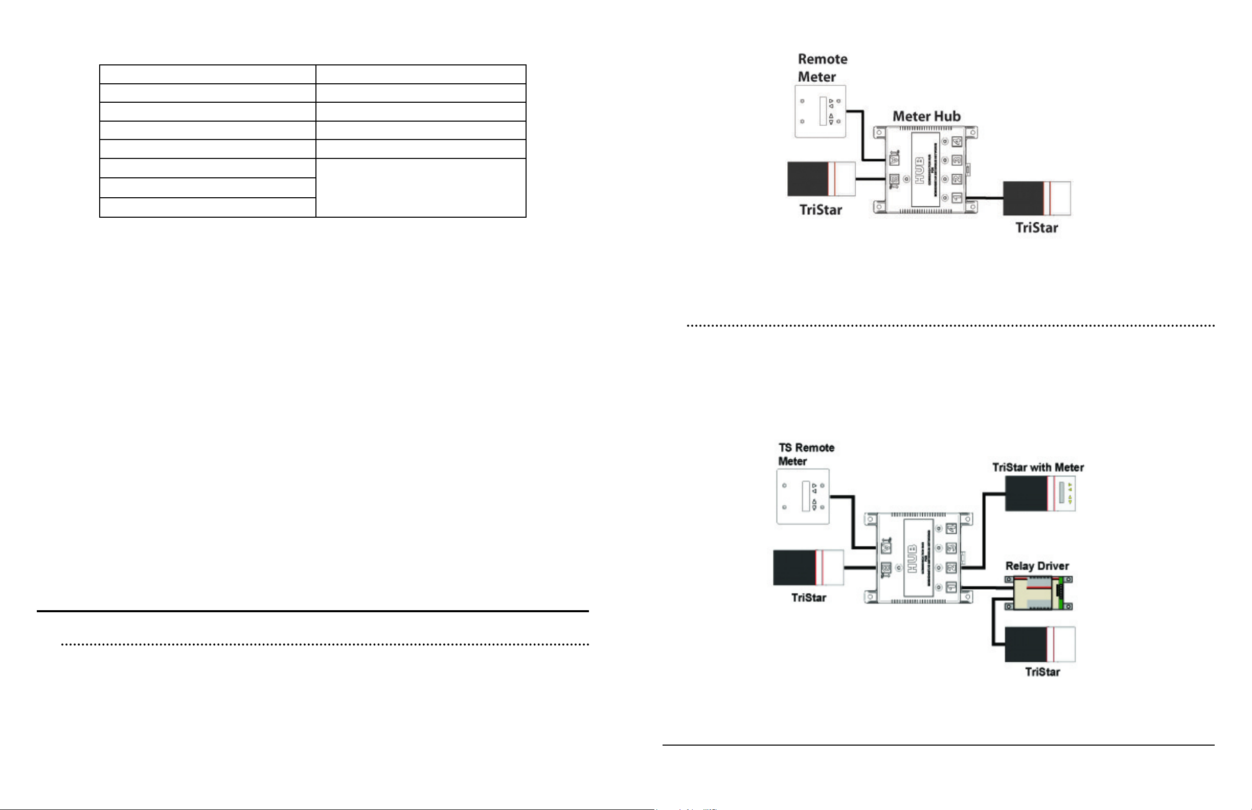
A typical medium-sized network can be found in Figure 20. This network is comprised of three
TriStars, two TS Meters, one Relay Driver, and one Meter Hub. As with the small network, the
TS Remote Meter is powered via the TriStar on Input Power Port B. Remember: Only two meters are allowed on a single MeterBusTM network. Notice that the Relay Driver is a device that
requires power, yet is connected to Port 1 (a port that does not supply output power). A TriStar is
used to power the RD-1 in this case.
3.3.1 Example #1 - Small Network
A typical small network is shown in Figure 19 below. The TriStar connected to Port B is electrical-
ly isolated from the TriStar on Port 1. This prevents dierences in ground potential, disconnected
grounds, or diering system voltage to damage the network equipment or controllers. The TS
Remote Meter connected to Output Power Port A is powered from the TriStar connected to Port
B and is also isolated from Port 1.
MeterBusTM Networking
Figure 20. Morningstar MeterBusTM Medium-Sized Network Diagram
21Morningstar Product Connectivity Manual20
3.3.3 Example #3 - RD-1 Polling Network
A Relay Driver used in conjunction with a Meter Hub allows the Relay Driver to poll multiple
controllers and trigger alarms based upon specic controller inputs. For example, the RD-1 could
trigger an alarm for overcurrent on one of the controllers, while simultaneously triggering an
alarm for LVD on one of the other controllers. Note that the Relay Driver is connected to Output
Power Port A because it does not supply its own power to the MeterBus
TM
network.
Figure 21. Morningstar MeterBusTM RD-1 Polling Network Diagram
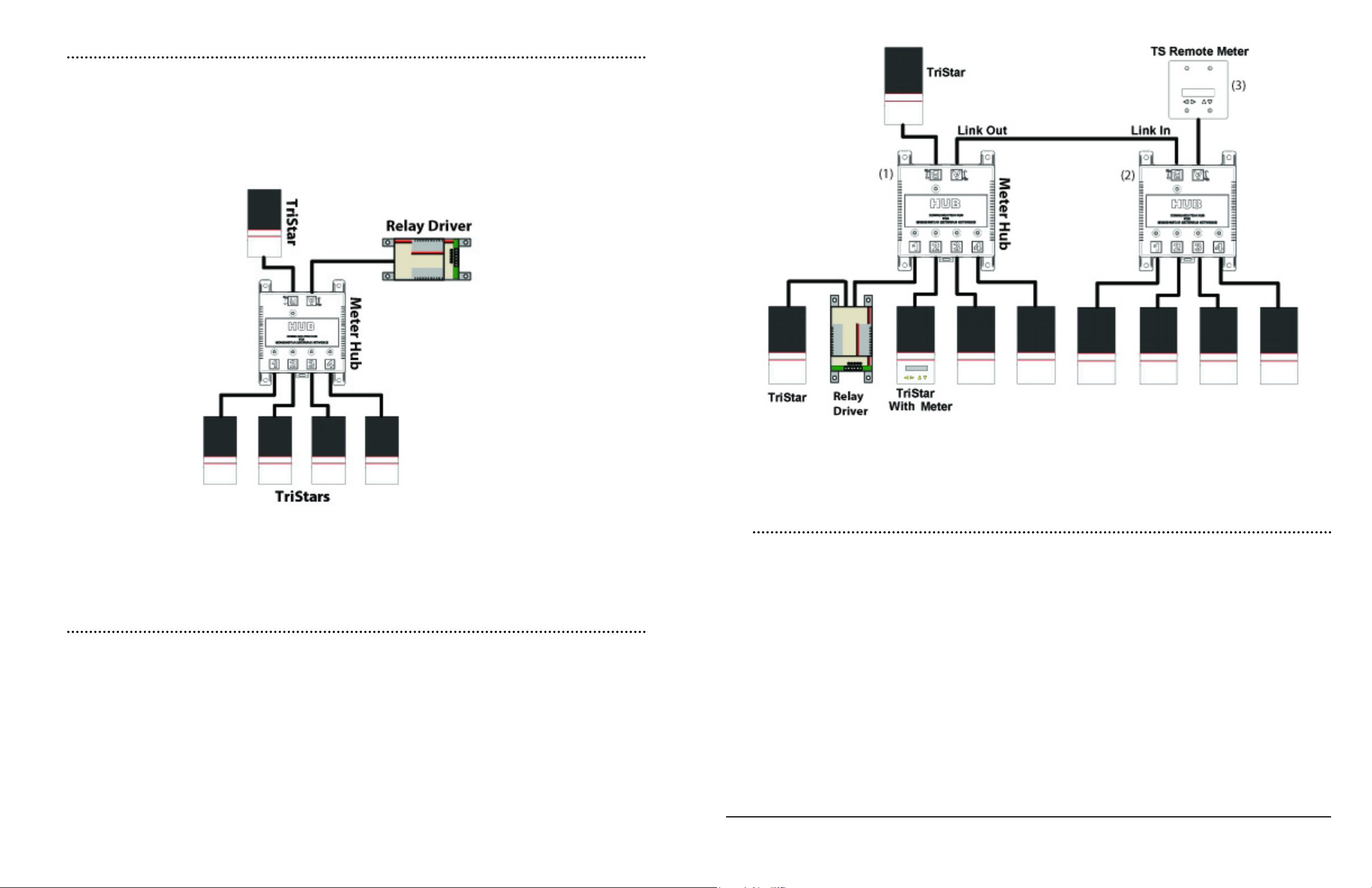
3.3.4 Example #4 - Large, Multiple Hub Network 1
Figure 22 illustrates a large MeterBusTM network making use of multiple Meter Hubs. The two
hubs are linked using the Link Out / Link In Ports A & B, respectively. Each hub expands the
number of MeterBusTM connections to the network. Notice that the TriStar powering the hubs
can only accommodate a maximum of three (labeled 1-3) devices that require power (two hubs
and one TS Remote Meter in the diagram below). Remember: A maximum of four Hubs may be
linked on one MeterBusTM network, accommodating up to 15 MeterBusTM devices. Regardless of
how many Hubs are used, all networking rules concerning power management still apply.
Figure 22. Morningstar MeterBusTM Large, Multiple Hub Network Diagram 1
3.3.5 Example #5 - Large, Multiple Hub Network 2
Device power requirements will sometimes call for a network setup as illustrated in Figure 23.
This multiple hub network connects hubs in a dierent manner than in Example #4. Since the
TriStar (with Meter) can only power up to three devices (Meter, Hub, Relay Driver - denoted 1
through 3 in the diagram), the output link of the Relay Driver cannot be connected to the input of
the second hub. Another unit that provides power (i.e. TriStar) is used to power the second hub
and TS Remote Meter. To network the two hubs, the output link of the Relay Driver (3) is connected to one of the isolated ports on the second hub.
Figure 23 illustrates only one example of the way these 14 units can be networked together.
MeterBusTM Networking
23Morningstar Product Connectivity Manual22
 Loading...