

Morningstar SS-10-12V, SS-6-12V, SS-6L-12V, S-20L-24V, SS-20L-12V Installation And Operation Manual
...
Installation and Operation Manual
www.morningstarcorp.com
MORNINGSTAR
World’s Leading Solar Controllers & Inver ters
S
UN
S
AVER
PV SYSTEM CONTROLLERS
SunSaver Models Included in this Manual:
• SS-6-12V / SS-6L-12V
• SS-10-12V
• SS-10L-12V / SS-10L-24V
• SS-20L-12V / SS-20L-24V
MORNINGSTAR CORPORATION
3
2
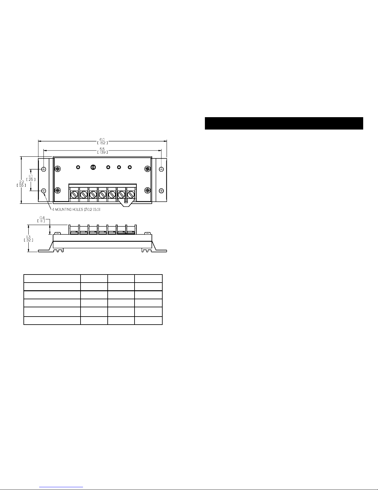
SunSaver Dimensions
Inches [Millimeters]
Specication Summary
Ratings SS-6/6L SS-10/10L SS-20L
System Voltage 12 V 12V or 24V 12V or 24V
Min. Battery Voltage 6 V 6 V 6 V
Max. Solar Voltage 30 V 30V or 60V 30V or 60V
Max. Solar Current 6 .5 A 10 A 20 A
Max. Load Current 6 A 10 A 20 A
See Section 7.0 for full technical specications
** Array voltage should never exceed maximum input voltage. Refer to the
solar module documentation to determine the highest expected array V
oc
as
dened by the lowest expected ambient temperature for the system location.
CONTENTS
1.0 Safety Information 4
2.0 General Information 10
2.1 Overview 10
2.2 Features 11
2.3 Regulatory Information 12
3.0 Installation Instructions 15
3.1 General Installation Notes 15
3.2 User Selections 16
3.3 Mounting 19
3.4 Wiring 21
4.0 Operation 31
4.1 LED Indications 31
4.2 Battery Charging Information 33
4.3 Load Control Information 35
4.4 Protections 37
4.5 Inspection and Maintenance 39
5.0 Troubleshooting 40
5.1 Error Indications 40
5.2 Common Problems 41
6.0 Warranty and Claim Procedure 42
7.0 Technical Specications 44
MORNINGSTAR CORPORATION
1.0 IMPORTANT SAFETY INSTRUCTIONS
5
4
1.0
SAVE THESE INSTRUCTIONS.
This manual contains important safety, installation and operating
instructions for the SunSaver solar controller.
The following symbols are used throughout this manual to indicate potentially dangerous conditions or mark important safety
instructions:
WARNING:
Indicates a potentially dangerous condition. Use
extreme caution when performing this task.
!
CAUTION:
Indicates a critical procedure for safe and proper
operation of the controller.
NOTE:
Indicates a procedure or function that is important for
the safe and proper operation of the controller.
WARNING:
These servicing instructions are for use by qualied
personnel only. To reduce the risk of electric shock,
do not perform any servicing other than that specied in
the operating instructions unless you are qualied
to do so.
Safety Information
• Read all of the instructions and cautions in the manual before
beginning installation.
• There are no user serviceable parts inside the SunSaver. Do
not disassemble or attempt to repair the controller.
• Disconnect all sources of power to the controller before
installing or adjusting the SunSaver.
• There are no fuses or disconnects inside the SunSaver. Do
not attempt to repair.
• Install external fuses/breakers as required.
!
CAUTION:
A BATTERY CAN PRESENT A RISK OF ELECTRICAL
SHOCK, BURN FROM HIGH SHORT-CIRCUIT
CURRENT, FIRE OR EXPLOSION FROM VENTED GASES.
OBSERVE PROPER PRECAUTIONS;
NOTE:
PROPER DISPOSAL OF BATTERIES IS REQUIRED.
REFER TO YOUR LOCAL CODES FOR DISPOSAL
REQUIREMENTS;
WARNING:
These servicing instructions are for use by qualied
personnel only. To reduce the risk of electric shock,
do not perform any servicing other than that specied in
the operating instructions unless you are qualied
to do so.
WARNING:
EXPLOSION HAZARD - DO NOT DISCONNECT WHILE
CIRCUIT IS LIVE UNLESS AREA IS
KNOWN TO BE NON-HAZARDOUS.
!
CAUTION:
To reduce the risk of re, connect only to a circuit
provided with a maximum branch-circuit overcurrent
protection rating not to exceed the model current rating
on page 2 and in accordance with the National Electrical
Code, ANSI/NFPA 70.
CAUTION:
Unit has no battery removal protection.
Disconnecting battery during charging may cause a
brief spike in load voltage (above the 15V
regulation limit) which may damage sensitive equipment.
1.0 Important Safety Information 4
!
1.0 IMPORTANT SAFETY INSTRUCTIONS
MORNINGSTAR CORPORATION
1.0 IMPORTANT SAFETY INSTRUCTIONS
7
6
1.0
!
ATTENTION:
Pour diminuer le risque d’incendie, ne connectez
l’alimentation qu’à un circuit équipé d’une protection
maximum par dérivation contre les surintensités ne
dépassant pas le courant nominal du modèle de la
page 2, conformément à la norme du Code National de
l’Électricité (NEC), ANSI/NFPA 70.
ATTENTION:
Unité bénécie d’aucune protection de retrait de batterie.
Débrancher la batterie pendant la charge peut entraîner
un bref pic de tension de charge (au-dessus du 15V limite
de règlement) qui peuvent endommager les équipement
sensibles.
Installation Safety Precautions
WARNING:
This unit is not provided with a GFDI device. This
charge controller must be used with an external
GFDI device as required by the Article 690 of
the National Electrical Code for the installation
location.
• Mount the SunSaver indoors. Prevent exposure to the
elements and do not allow water to enter the controller.
• Install the SunSaver in a location that prevents casual
contact. The SunSaver heatsink can become very hot during
operation.
• Use insulated tools when working with batteries.
• Avoid wearing jewelry during installation.
• The battery bank must be comprised of batteries of same
type, make, and age.
• Do not smoke in the vicinity of the battery bank.
• Mount the controller at least 3 ft (1 m) away from vented
batteries unless separated by a barrier or located in a
separate compartment.
Installation in Hazardous Locations
THIS EQUIPMENT IS SUITABLE FOR USE IN CLASS I, DIVISION
2, GROUPS A,B,C and D OR NON-HAZARDOUS LOCATIONS
ONLY.
Informations de sécurité
• Lisez toutes les instructions et les avertissements gurant
dans le manuel avant de commencer l’installation.
• Le SunSaver ne contient aucune pièce réparable par
l’utilisateur. Ne démontez pas ni ne tentez de réparer le
contrôleur.
• Déconnectez toutes les sources d’alimentation du contrôleur
avant d’installer ou de régler le SunSaver.
• Le SunSaver ne contient aucun fusible ou interrupteur. Ne
tentez pas de réparer.
• Installez des fusibles/coupe-circuits externes selon le besoin.
!
ATTENTION:
UNE BATTERIE PEUT PRÉSENTER UN RISQUE ÉLEVÉ
DE CHOC ÉLECTRIQUE, DE BRÛLURES SUITE À UN
COURANT DE COURT-CIRCUIT ÉLEVÉ, À UN INCENDIE
OU À UNE EXPLOSION PROVENANT DE GAZ REJETÉS
DANS L’AIR. VEUILLEZ PRENDRE LES PRÉCAUTIONS
NÉCESSAIRES.
AVERTISSEMENT:
Ces instructions d’entretien sont exclusivement réservé-
es à des techniciens qualiés. Pour réduire le risque de
choc électrique,
ne réalisez aucun entretien autre que celui stipulé dans
les instructions de fonctionnement, à moins que vous ne
possédiez les qualications nécessaires en la matière.
AVERTISSEMENT:
RISQUE D’EXPLOSION. NE PAS DEBRANCHER TANT
QUE LE CIRCUIT EST SOUS TENSION, A MOINS QU’lL
NE S’AGISSE D’UN EMPLACEMENT NON DANGEREUX.
!
1.0 IMPORTANT SAFETY INSTRUCTIONS
8
MORNINGSTAR CORPORATION
1.0
9
• Power connections must remain tight to avoid excessive
heating from a loose connection.
• Use properly sized conductors and circuit interrupters
• This charge controller is to be connected to DC circuits only.
These DC connections are identied by the symbol below.
Direct Current Symbol
AVERTISSEMENT:
L’appareil n’est pas fourni avec un dispositif GFDI.
Ce contrôleur de charge doit être utilisé avec un
dispositif GFDI externe tel que requis par l’Article
690 du Code électrique national de l’emplacement de
l’installation.
• Montez le SunSaver à l’intérieur. Empêchez l’exposition aux
éléments et la pénétration d’eau dans le contrôleur.
• Utilisez des outils isolés pour travailler avec les batteries.
• Évitez le port de bijoux pendant l’installation.
• Le groupe de batteries doit être constitué de batteries du
même type, fabricant et âge.
• Ne fumez pas à proximité du groupe de batteries.
• Les connexions d’alimentation doivent rester serrées pour
éviter une surchauffe excessive d’une connexion desserrée.
• Utilisez des conducteurs et des coupe-circuits de dimensions
adaptées.
• Ce contrôleur de charge ne doit être connecté qu’à des cir-
cuits en courant continu. Ces connexions CC sont identiées
par le symbole ci-dessous:
• Le contrôleur SunSaver doit être installé par un technicien
qualié conformément aux règlementations électriques du
pays où est installé le produit.
• Un moyen d’assurer la déconnexion de tous les pôles de
l’alimentation doit être fourni. Cette déconnexion doit être
incorporée dans le câblage xe.
• À l’aide de la borne de mise à la masse du SunSaver (dans le
compartiment de câblage), un moyen permanent et able de
mise à la terre doit être fourni. La xation de la mise à la terre
doit être xée contre tout desserrage accidentel.
• Les ouvertures d’entrée au compartiment de câblage du
SunSaver doivent être protégées avec un conduit ou une
bague.
MORNINGSTAR CORPORATION
11
10
2.1 Overview
Thank you for selecting the SunSaver solar charge
controller. The SunSaver is an advanced PWM solar battery
charger and load controller for stand-alone PV systems.
The SunSaver battery charging process has been
optimized for long battery life and improved system
performance. Self-diagnostics and electronic error protection
prevent damage when installation mistakes or system faults
occur.
Although the SunSaver is very simple to install and use,
please take the time to read this operator’s manual and
become familiar with the controller.
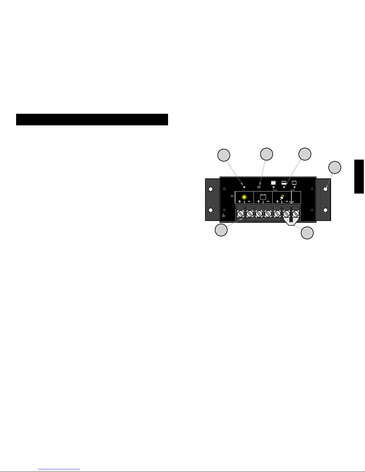
2.2 Features
The features of the SunSaver are shown in Figure 1 below.
An explanation of each feature is provided.
SEALED
OR
FLOODED
SELECT
LOAD
BATTERY
SOLAR
Remove
Jumper
Wire for
Flooded
Battery
{
12 V
BATTERY STATUSTEMP. SENSORCHARGING STATUS
!
See Operator’s
Manual
Nominal Rating
12 Volts dc
Max. Input 30 V
Solar 6.5 A
Battery 6.5 A
Load 10.0 A
indoor use only
Use Copper
Conductors Only
CONFORMS TO UL STD 1604
CERTIFIED TO CAN/CSA STD
C22.2 NO.213-M1987
Class 1 Division 2
Groups A,B,C,D
Hazardous Loc.
For the Risk of Explosion Only
Operating Temp. Code: T5
MORNINGSTAR
S S
6
UN AVER-
SOLAR CONTROLLER SS-6-12V
1
2
6
54
3
Figure 1. SunSaver features.
1 - Status LED
An LED indicator that shows charging status and also
indicates when a solar input fault condition exists.
2 - Power Terminal Block
Power terminations for system Solar, Battery, and Load
connections.
3 - Battery Select Jumper
A removable jumper to select the battery type.
4 - Local Temperature Sensor
Measures ambient temperature. Battery regulation is
adjusted based on ambient temperature changes.
2
2 .0
2.0 GENERAL INFORMATION
2.0 GENERAL INFORMATION
MORNINGSTAR CORPORATION
2.0 GENERAL INFORMATION
13
12
5 - Battery Status LEDs
Provides approximate battery state-of-charge indication
and also indicates when a system or load fault condition
exists.
6 - Mounting Holes
Four (4) mounting holes
2.3 Regulatory Information
NOTE:
This section contains important information for safety
and regulatory requirements.
The SunSaver controller should be installed by a qualied
technician according to the electrical regulations of the
country in which the product will be installed.
SunSaver controllers comply with the following EMC
standards:
• Immunity: EN61000-6-2:1999
• Emissions: EN55022:1994 with A1 and A3 Class B1
• Safety: EN60335-1 and EN60335-2-29 (battery
chargers)
FCC requirements:
This device complies with Part 15 of the FCC rules.
Operation is subject to the following two conditions: (1)
This device may not cause harmful interference, and (2)
this device must accept any interference received, including
interference that may cause undesired operation.
Changes or modications not expressly approved by
Morningstar for compliance could void the user’s authority to
operate the equipment.
Note:
This equipment has been tested and found to comply
with the limits for a Class B digital device, pursuant to Part
15 of the FCC rules. These limits are designed to provide
reasonable protection against harmful interference in a
residential installation. This equipment generates, uses, and
can radiate radio frequency energy and, if not installed and
used in accordance with the instruction manual, may cause
harmful interference to radio communication. However,
there is no guarantee that interference will not occur in a
particular installation. If this equipment does cause harmful
interference to radio or television reception, which can be
determined by turning the equipment on and off, the user is
encouraged to try to correct the interference by one or more
of the following measures:
• Re-orient or relocate the receiving antenna.
• Increase the separation between the equipment and
receiver.
• Connect the equipment into an outlet on a circuit
different from that to which the receiver is connected.
• Consult the dealer or an experienced radio/TV
technician for assistance.
2
2 .0
MORNINGSTAR CORPORATION
15
2.0 GENERAL INFORMATION
14
This Class B digital apparatus complies with Canadian
ICES-003.
Cet appareil numerique de la classe B est conforme a la
norme NMB-003 du Canada.
3.0 INSTALLATION INSTRUCTIONS
3.1 General Installation Notes
• Read through the entire installation section before
beginning installation.
• Be very careful when working with batteries. Wear
eye protection. Have fresh water available to wash
and clean any contact with battery acid.
• Use insulated tools and avoid placing metal objects
near the batteries.
• Explosive battery gases may be present during charg-
ing. Be certain there is sufcient ventilation to
release the gases.
• Do not install in locations where water can enter the
controller.
• Loose power connections and/or corroded wires
may result in resistive connections that melt wire
insulation, burn surrounding materials, or even cause
re. Ensure tight connections and use cable clamps
to secure cables and prevent them from swaying in
mobile applications.
• The SunSaver charging algorithm is compatible with
lead-acid or NiCd batteries. NiMH, Li-ion, and other
battery chemistries are not compatible with the
SunSaver charging algorithm.
• The SunSaver Battery connection may be wired
to one battery or a bank of batteries. The following
instructions refer to a singular battery, but it is implied
that the battery connection can be made to either one
battery or a group of batteries in a battery bank.
2
3 .0
 Loading...