

Morningstar PS-MPPT-25, PS-MPPT-25M, PS-MPPT-40, PS-MPPT-40M Maintance Manual
Solar Charging System Controller
Installation, Operation and Maintenance Manual
www.morningstarcorp.com
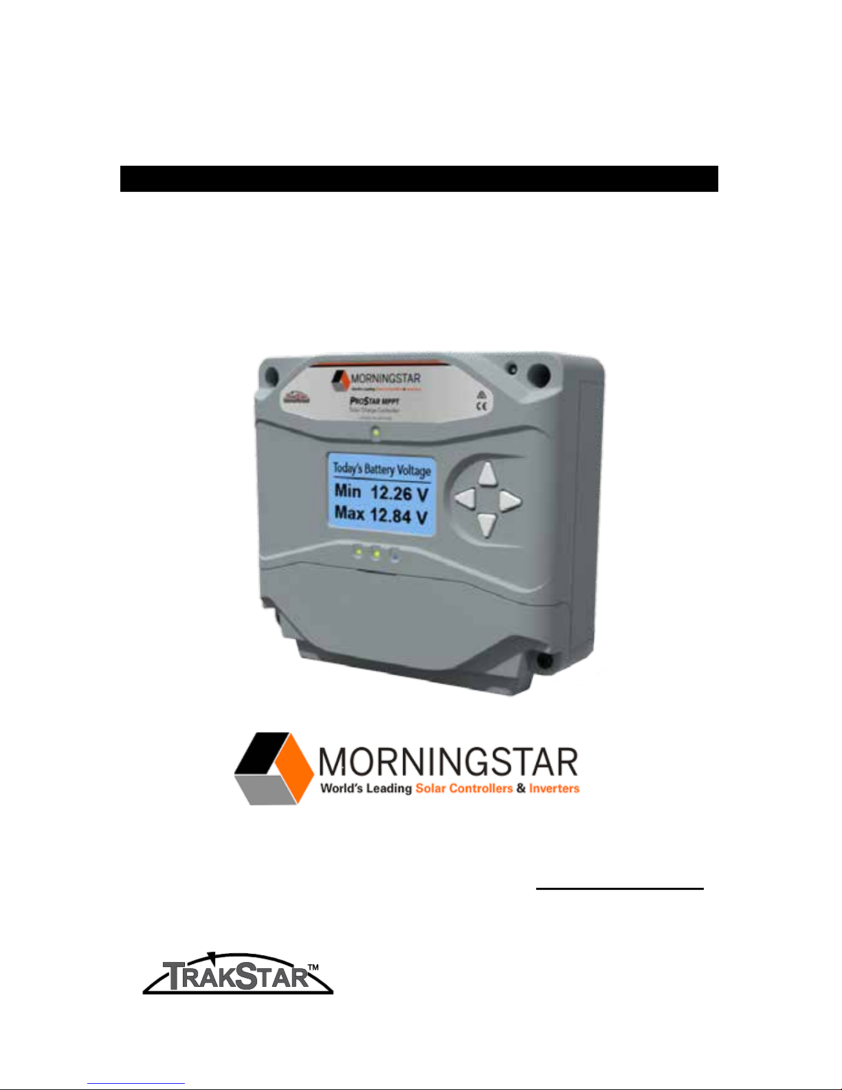
ProStar MPPT
TM
MODELS
PS-MPPT-25
PS-MPPT-25M
PS-MPPT-40
PS-MPPT-40M
MAXIMUM POWER POINT TRACKING
For the most recent manual revisions, see the version at:
www.morningstarcorp.com
ProStar MPPT Operator’s Manual
iii
ii
ProStar MPPT Operator’s Manual
SPECIFICATION SUMMARY
PS-MPPT-25 PS-MPPT-40
Nominal Battery
Voltage
12/24V 12/24V
Max. PV Open-
Circuit Voltage*
120V 120V
Maximum Operating
Power**
350 / 700W
550 /
1100W
Max. Battery
Charging Current
25A 40A
Rated Load Current 25A 30A
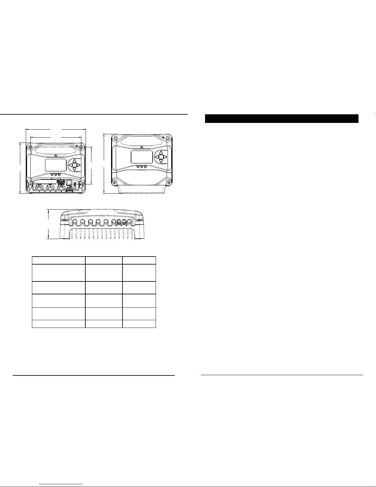
DIMENSIONS [inches (centimeters)]
TABLE OF CONTENTS
1.0 Important Safety Instructions ............................ 1
2.0 General Information .... .................................... ..10
2.1 Overview
...............................................................10
2.2 Regulatory Information........................................11
2.3 Versions and Ratings................................................13
2.4 Features
................................................................14
2.5 Optional Accessories
.............................................16
3.0 Installation ............................................................18
3.1 General Installation Notes
.....................................18
3.2 Configuration
........................................................21
3.3 Mounting
..............................................................24
3.4 Wiring
..................................................................25
4.0 Operation .............................................................35
4.1 TrakStar MPPT Technology ...................................... 35
4.2 Battery Charging Information ..................................37
4.3 Load Control Information ....................................... 47
4.4 LED Indications......................................... .... ....... .49
4.4.1 Power-up............................................................... .49
4.4.2 Status LED.............................................................. 49
4.4.3 State-of-charge LEDs...............................................50
4.5 Push-button Use in Non-Metered Version.............50
4.6 Alarms......................................................................51
4.7 Custom Settings............................. ........................53
4.7.1 Programming with Meter Display........................... 53
4.7.2 Programming in MSView.........................................54
4.7.3 Meter Display Operation.........................................55
4.7.3.1 Directional Key Use and Operation / Navigating
the Meter Map.......................................................55
4.7.3.2 Adjusting the Meter Display...................................55
**These power levels refer to the maximum wattage the PS-MPPT
can process. Higher power arrays can be used without damaging the
controller.
*Array voltage should never exceed this limit
6.69
( 17.0 )
6.69
( 17.0 )
4.92
( 12.5 )
7.88
( 20.0 )
7.62
( 19.4 )
2.76
( 7.0 )
1.0
ProStar MPPT Operator’s Manual
1
iv
ProStar MPPT Operator’s Manual
1.0 IMPORTANT SAFETY INSTRUCTIONS
SAVE THESE INSTRUCTIONS.
This manual contains important safety, installation, operating
and maintenance instructions for the ProStar MPPT solar
controller.
The following symbols are used throughout this manual to
indicate potentially dangerous conditions or mark important
safety instructions:
WARNING: Indicates a potentially dangerous condition.
Use extreme caution when performing this task.
CAUTION: Indicates a critical procedure for safe and
proper operation of the controller.
NOTE: Indicates a procedure or function that is important
to the safe and proper operation of the controller.
CONSIGNES IMPORTANTES DE SÉCURITÉ
CONSERVEZ CES INSTRUCTIONS:
Ce manuel contient des instructions importantes de sécurité,
d’installations et d’utilisation du contrôleur solaire ProStar
MPPT.
Les symboles suivants sont utilisés dans ce manuel pour
indiquer des conditions potentiellement dangereuses ou des
consignes importantes de sécurité.
AVERTISSEMENT: Indique une condition potentiellement
dangereuse. Faites preuve d’une prudence extrême lors
de la réalisation de cette tâche.
PRUDENCE: Indique une procédure critique pour
l’utilisation sûre et correcte du contrôleur.
REMARQUE: Indique une procédure ou fonction
importante pour l’utilisation sûre et correcte du
contrôleur.
4.7.4 Using the Meter Display to Program Charging
Set-points, Load Control, Communications, and
Advanced Settings....................................................55
4.7.5 Lighting Control / Programming Overview...............55
4.7.6 Lighting Programming Using Meter Display.............56
4.8 Inspection and Maintenance..................................... 57
5.0 Troubleshooting...........................................59
5.1 LED Fault Indications.................................................. .59
5.2 Battery Charging and Performance Issues..................64
6.0 Warranty and Policies..................................65
7.0 Technical Specifications...............................69
8.0 Certifications...............................................72
Appendix A - Efficiency.........................................73
Appendix B - De-rating Graphs..........................75
Appendix C - Wire Sizing Charts............................76
1.0
Important Safety Instructions
ProStar MPPT Operator’s Manual
32
AV ERTISSEMENT: Risque De Choc Électrique.
NON ALIMENTATION OU AUX BORNES
D'ACCESSOIRES SONT ISOLÉS ÉLECTRIQUEMENT DE
L'ENTRÉE DE C.C ET DOIT ÊTRE ALIMENTÉS À UNE TENSION
DANGEREUSE SOLAIRE. SOUS CERTAINES CONDITIONS
DE DÉFAILLANCE, LA BATTERIE POURRAIT DEVENIR TROP
CHARGÉE. TEST ENTRE TOUTES LES BORNES ET LA MASSE
AVANT DE TOUCHER.
AVERTISSEMENT: LE PORT DE COMMUNICATION EST
CONSIDÉRÉE COMME DVC B. UN ISOLATEUR EXTERNE
N'EST NÉCES SAIRE SI C'EST D'ÊTRE CONNECTÉ À UN DVC
UN CIRCUIT.
• External solaire et la batterie se déconnecte sont
nécessaires.
• Déconnectez toutes les sources d’alimentation du
contrôleur avant d’installer ou de régler le ProStar MPPT.
• Le ProStar MPPT MPPT ne contient aucun fusible ou interrupteur. Ne tentez pas de réparer.
• Installez des fusibles/coupe-circuits externes selon le
besoin.
Installation Safety Precautions
WARNING: This unit is not provided with a GFDI device.
This charge controller must be used with an external
GFDI device as required by the Article 690 of the
National Electrical Code for the installation location.
• Mount the ProStar MPPT indoors. Prevent exposure to the
elements and do not allow water to enter the controller.
• Install the ProStar MPPT in a location that prevents casual
contact. The ProStar MPPT heatsink can become very hot
during operation.
• Use insulated tools when working with batteries.
• Avoid wearing jewelry during installation.
Safety Information
• Read all of the instructions and cautions in the manual
before beginning installation.
• There are no user serviceable parts inside the
ProStar MPPT. Do not disassemble or attempt to repair
the controller.
WARNING: Risk Of Electrical Shock.
NO POWER OR ACCESSORY TERMINALS ARE
ELECTRICALLY ISOLATED FROM DC INPUT, AND MAY BE
ENERGIZED WITH HAZARDOUS SOLAR VOLTAGE. UNDER
CERTAIN FAULT CONDITIONS, BATTERY COULD BECOME
OVER-CHARGED. TEST BETWEEN ALL TERMINALS AND
GROUND BEFORE TOUCHING.
WARNING: THE COMMUNICATIONS PORT IS
CONSIDERED TO BE DVC B. AN EXTERNAL
ISOLATOR IS REQUIRED IF IT IS TO BE CONNECTED TO A DVC
A CIRCUIT.
• External solar and battery disconnects are required.
• Disconnect all sources of power to the controller before
installing or adjusting the ProStar MPPT.
• There are no fuses or disconnects inside the ProStar MPPT
Do not attempt to repair.
Informations de Sécurité
• Lisez toutes les instructions et les avertissements figurant
dans le manuel avant de commencer l’installation.
• Le ProStar MPPT ne contient aucune pièce réparable par
l’utilisateur. Ne démontez pas ni ne tentez de réparer le
contrôleur.

1.0
Important Safety Instructions
ProStar MPPT Operator’s Manual
54
• The battery bank must be comprised of batteries of same
type, make, and age.
• UL/IEC 62109 certified for use in negative ground or
floating systems only.
• Do not smoke near the battery bank.
• Power connections must remain tight to avoid excessive
heating from a loose connection.
• Use properly sized conductors and circuit interrupters.
• The grounding terminal is located in the case, and is
identified by the symbol below:
Ground Symbol
• This charge controller is to be connected to DC circuits
only. These DC connections are identified by the symbol
below:
Direct Current Symbol
The ProStar MPPT controller must be installed by a qualified
technician in accordance with the electrical regulations of
the country of installation.
A means of disconnecting all power supply poles must be
provided. These disconnects must be incorporated in the
fixed wiring.
The ProStar MPPT negative power terminals are common,
and must be grounded as instructions, local codes, and
regulations require.
A permanent, reliable earth ground must be established
with connection to the ProStar MPPT ground terminal.
The grounding conductor must be secured against any
accidental detachment.
Précautions de Sécurité D’installation
AVERTISSEMENT: L’appareil n’est pas fourni avec un
dispositif GFDI. Ce contrôleur de charge doit être
utilisé avec un dispositif GFDI externe tel que requis
par l’Article 690 du Code électrique national de
l’emplacement de l’installation.
• Montez le ProStar MPPT à l’intérieur. Empêchez
l’exposition aux éléments et la pénétration d’eau dans le
contrôleur.
• Installez le MPPT ProStar dans un endroit qui empêche
le contact occasionnel. Le dissipateur de chaleur ProStar MPPT peut devenir très chaud pendant le fonctionnement.
• Utilisez des outils isolés pour travailler avec les batteries.
• Évitez le port de bijoux pendant l’installation.
• Le groupe de batteries doit être constitué de batteries du
même type, fabricant et âge.
• UL/IEC 62109 certifié pour utilisation au négatif à la
masse ou les systèmes flottants seulement.
• Ne fumez pas à proximité du groupe de batteries.
• Les connexions d’alimentation doivent rester serrées
pour éviter une surchauffe excessive d’une connexion
desserrée.
• Utilisez des conducteurs et des coupe-circuits de dimensions adaptées.
• La borne de mise à la terre se trouve dans l'affaire et est
identifié par le symbole ci-dessous :
1.0
Important Safety Instructions
ProStar MPPT Operator’s Manual
76
• Ce contrôleur de charge ne doit être connecté qu’à
des circuits en courant continu. Ces connexions CC sont
identifiées par le symbole ci-dessous:
Le régulateur MPPT ProStar doit être installé par un
technicien qualifié conformément aux règlements du pays
d'installation électriques.
Un moyen de déconnexion de tous les poteaux
d'alimentation doit être fourni. Ceux-ci se déconnecte doit
être intégrée dans le câblage fixe.
Une mise à la terre permanent et fiable s'impose avec
raccordement à la borne ProStar MPPT.
Les bornes de puissance négative ProStar MPPT sont communs et doivent être mise à la terre comme les directives, les
codes locaux, et les règlements exigent.
Le conducteur de terre doit être protégée contre tout détachement accidentel.
Battery Safety
WARNING: A battery can present a risk of electrical
shock or burn from large amounts of short-circuit
current, fire, or explosion from vented gases.
Observe proper precautions.
AVE RTISSEMENT: Une batterie peut présenter a ris
que de choc électrique ou de brûlure de grandes
quantités de court-circuit curlouer, incendie ou
explosion de ventilé gaz. Observer précautions
appropriées.
WARNING: Risk of Explosion.
Proper disposal of batteries is required. Do not
dispose of batteries in fire. Refer to local
regulations or codes for requirements.
AVERTISSEMENT: Risque d'Explosion.
Au rebut des piles est nécessaire. Ne pas jeter les piles
dans le feu. Se référer aux réglementations locales ou
des codes pour les exigences.
CAUTION: When replacing batteries, use properly
specified number, sizes, types, and ratings based on
application and system design.
PRUDENCE: Lorsque le remplacement des piles,
utilisez correctement nombre spécifié, tailles, types et
les évaluations basées sur conception de système et
d'application.
CAUTION: Do not open or mutilate batteries.
Released electrolyte is harmful to skin, and may be
toxic.
PRUDENCE: Ne pas ouvrir ou mutiler les piles.
L'électrolyte est nocif pour la peau et peut être
toxique.
• Servicing of batteries should be performed, or supervised,
by personnel knowledgeable about batteries, and the
proper safety precautions.
• Be very careful when working with large lead-acid
batteries. Wear eye protection and have fresh water
available in case there is contact with the battery acid.
• Remove watches, rings, jewelry and other metal objects
before working with batteries.
• Wear rubber gloves and boots
• Use tools with insulated handles and avoid placing tools
or metal objects on top of batteries.
• Disconnect charging source prior to connecting or
disconnecting battery terminals.
• Determine if battery is inadvertently grounded. If so,
remove the source of contact with ground. Contact with
any part of a grounded battery can result in electrical
shock. The likelihood of such a shock can be reduced

1.0
Important Safety Instructions
ProStar MPPT Operator’s Manual
98
if battery grounds are removed during installation and
maint enance (applicable to equipment and remote
battery supplies not having a grounded supply circuit).
• Carefully read the battery manufacturer's instructions
before installing / connecting to, or removing batteries
from, the ProStar MPPT.
• Be very careful not to short circuit the cables connected
to the battery.
• Have someone nearby to assist in case of an accident.
• Explosive battery gases can be present during charging.
Be
certain there is enough ventilation to release the
gases.
• Never smoke in the battery area.
• If battery acid comes into contact with the skin, wash
with
soap and water. If the acid contacts the eye, flood
with fresh water and get medical attention.
• Be sure the battery electrolyte level is correct before starting
charging. Do not attempt to charge a frozen battery.
• Recycle the battery when it is replaced.
• Entretien des batteries devrait être effectué ou supervisé, par un personnel bien informé sur les piles et les
précautions de sécurité appropriées.
• Soyez très prudent quand vous travaillez avec des
grandes batteries au plomb. Portez des lunettes de protection et ayez de l’eau fraîche à disposition en cas de
contact avec l’électrolyte.
• Enlevez les montres, bagues, bijoux et autres objets mé
talliques avant de travailler avec des piles.
• Porter des bottes et des gants de caoutchouc
• Utiliser des outils avec poignées isolantes et évitez de
placer des outils ou des objets métalliques sur le dessus
de batteries.
• Débrancher la source de charge avant de brancher ou
dis-reliant les bornes de la batterie.
• Utilisez des outils isolés et évitez de placer des objets
métalliques dans la zone de travail.
• Déterminer si batterie repose par inadvertance. Dans
l'affirmative, supprimer la source du contact avec le sol.
Contact avec n'importe quelle partie d'une batterie mise
à la terre peut entraîner un choc électrique. La probabilité
d'un tel choc peut être réduite si des motifs de batterie
sont supprimés pendant l'installation et maintentretien
(applicable à l'équipement et les fournitures de pile de la
télécommande n'ayant ne pas un circuit d'alimentation
mise à la terre).
• Lisez attentivement les instructions du fabricant de la
batterie avant d'installer / connexion à ou retrait des
batteries du ProStar MPPT.
• Veillez à ne pas court-circuiter les câbles connectés à la
batterie.
• Ayez une personne à proximité qui puisse aider en cas
d’accident.
• Des gaz explosifs de batterie peuvent être présents pendant la charge. Assurez-vous qu’une ventilation suffisante
évacue les gaz.
• Ne fumez jamais dans la zone des batteries
• En cas de contact de l’électrolyte avec la peau, lavez avec
du savon et de l’eau. En cas de contact de l’électrolyte
avec les yeux, rincez abondamment avec de l’eau fraîche
et consultez un médecin.
• Assurez-vous que le niveau d’électrolyte de la batterie est
correct avant de commencer la charge. Ne tentez pas de
charger une batterie gelée.
• Recyclez la batterie quand elle est remplacée.

2.0
General Information
ProStar MPPT Operator’s Manual
11
10
2.1 Overview
Thank you for choosing the ProStar MPPT charge controller
with TrakStarTM MPPT Technology. The ProStar MPPT is an
advanced maximum power point tracking solar battery charger. The controller features a smart tracking algorithm that
finds and maintains operation at the power source's peak
power point, maximizing energy harvest.
The ProStar MPPT battery charging process has been
optimized for long battery life and improved system performance. Self-diagnostics and electronic error protections
prevent damage when installation mistakes or system faults
occur. The controller also features eight (8) adjustable settings switches, several communication ports, and terminals
for remote battery temperature and voltage measurement.
Please take the time to read this operator’s manual to
become familiar the many benefits the ProStar MPPT can
provide for your PV systems, for example:
• Rated for 12 or 24 volt systems, and 25 or 40 amps of
charging current
• Fully protected with automatic and manual recovery
• Seven standard charging programs selectable with DIP
switches
• Continuous self-testing with fault notification
• LED indications and push-button or meter key functions
• Terminals sized for #2 AWG (35mm
2
) wire - compliant
when used with the optional Morningstar Wire Box,
otherwise a maximum of #6 AWG wire.
• Includes battery voltage sense terminals
• Digital meter display options
• Optional remote battery temperature sensor
• 5-year warranty (see Section 6.0)
2.0 GENERAL INFORMATION
2.2 Regulatory Information
NOTE:
This section contains important
information for safety and regulatory
requirements.
FCC requirements:
This device complies with Part 15 of the FCC rules.
Operation is subject to the following two conditions:
(1) This device may not cause harmful interference,
and,
(2) this device must accept any interference
received, including interference that may cause
undesired operation.
Changes or modifications not expressly approved
by Morningstar for compliance could void the user’s
authority to operate the equipment.
NOTE: This equipment has been tested and found
to comply with the limits for a Class B digital
device, pursuant to Part 15 of the FCC rules. These limits
are designed to provide reasonable protection against
harmful interference in a residential installation. This
equipment generates, uses, and can radiate radio
frequency energy and, if not installed and used in
accordance with the instruction manual, may cause harmful
interference to radio communication. However, there is no
guarantee that interference will not occur in a particular
installation.
If this equipment does cause harmful interference to radio
or television reception, which can be determined by
turning the equipment on and off, the user is encouraged
to try to correct the interference by one or more of the
following measures:
• Re-orient or relocate the receiving antenna.
• Increase the separation between the equipment and
receiver.

2.0
General Information
ProStar MPPT Operator’s Manual
13
12
• Connect the equipment into an outlet on a circuit
different from that to which the receiver is connected.
• Consult the dealer, or an experienced radio/TV
technician for help.
This Class B digital apparatus complies with Canadian
ICES-003.
Cet appareil numerique de la classe B est conforme a la
norme NMB-003 du Canada.
2.3 Versions and Ratings
PS-MPPT-25
• Rated for maximum 25 amps continuous current
(battery or load)
• Designed for 12 or 24 VDC systems
PS-MPPT-25M
• Includes metering display
• Rated for maximum 25 amps continuous current (battery
or load)
• Designed for 12 or 24 VDC systems
PS-MPPT-40
• Rated for maximum 40 amps of continuous battery
current, and 30 amps of continuous load current
• Designed for 12 or 24 VDC systems
PS-MPPT-40M
• Includes metering display
• Rated for maximum 40 amps continuous battery current
and 30 amps of continuous load current
• Designed for 12 or 24 VDC systems
2.0
General Information
ProStar MPPT Operator’s Manual
15
14
2.4 Features
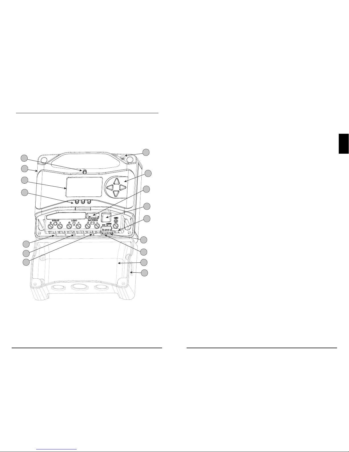
The features of the ProStar MPPT are shown in Figure 2-1
below. An explanation of each feature is provided.
11
10
12
15
16
14
4
2
3
1
5
8
6
13
9
7
Figure 2-1. PS-MPPT Features
1 - Charging Status / Error LED
Shows charging current and error condition statuses.
2 - Heatsink
Aluminum heatsink (underneath) to dissipate controller heat (the
ProStar MPPT is 100% passively cooled for reliability)
3 - Meter Display
Digital LCD monitoring and programming display
4 - Battery Status / Fault LED Indicators
Three state of charge (SOC) LED indicators show charging status and
controller faults
5 - Solar Positive and Negative Terminals
Power connections for Solar (+) and (-) cable terminations
6 - Load Positive and Negative Terminals
Power connections for Load (+) and (-) cable terminations
7 - Battery Positive and Negative Terminals
Power connections for Battery (+) and (-) cable terminations
8 - Local Temperature Sensor
Compensates charging based on ambient temperature (not used if Remote Temperature Sensor is connected)
9 - Meter Directional Buttons
Used to navigate throughout meter map
10 - DIP Switches
Eight (8) settings switches to configure operation of the ProStar MPPT
11 - MeterBusTM Port
RJ-11 socket for Morningstar MeterBusTM network connections
12 - Grounding Terminal
Chassis ground terminal for equipment grounding
13 - Battery Sense Terminals
Connection points for battery voltage sensing wires
14 - Remote Temperature Sensor Terminals (RTS)
Connection points for a Morningstar RTS to remotely monitor battery
temperature
15 - Wire Box for ProStar-MPPT
Optional accessory to route wiring through knock-outs
16 - Wire Box for ProStar-MPPT Knock-outs
Knock-outs for routing wires to conduit or wire gland terminations

2.0
General Information
ProStar MPPT Operator’s Manual
17
16
2.5 Optional Accessories
The following accessories are available for purchase
separately from your authorized Morningstar dealer:
Remote Temperature Sensor (Model: RTS)
The RTS measures battery temperature for accurate temper
ature compensation and is recommended when the ambient battery temperature differs from the ambient controller
temperature by more than 5º C. The standard cable length
is 33 ft (10m).
N
OTE: The use of a Remote Temperature Sensor is
strongly recommended. Controller location, air flow, and
system power can drastically affect the local temperature sensor
reading. An RTS will provide optimal charg
ing performance.
RM-1 Meter
The digital Remote Meter displays system operating information, error indications, and self-diagnostic read-out.
Information is displayed on a backlit 4-digit custom LCD display. The large numerical display and icons are easy to read
and large buttons make navigating the meter menus easy.
Additionally, a status LED and three (3) battery SOC LEDs
provide system status at a glance.
The meter can be flush mounted in a wall or surface
mounted using the mounting frame (included). The RM-1 is
supplied with 33 ft (10.0 m) of cable, a mounting frame, and
mounting screws. The RM-1 connects to the RJ- 11 Meter
port on the ProStar MPPT.
RelayDriver (RD-1)
The Relay Driver
TM
accessory enables the ProStar MPPT to
control external devices. Four (4) relay control ports can be
configured (in various combinations) to perform the
following tasks:
• generator control (2, 3, and 4-wire configurations)
• dry contacts for alarms and other signals
• advanced load control
• vent fan control
• DIN rail compatible or surface mount
Ground-fault Protection Device (GFPD-150V)
The GFPD-150V detects power source ground faults
and interrupts current as required by the U.S. National
Electrical Code.
Wire Box for ProStar MPPT
A modular wiring box that can be added to any version of
ProStar MPPT controller. The box acts as a junction (using
knock-outs) to run controller wiring to external conduit, if
desired. The wire box cannot be used with rigid conduit.
The communications accessories / adaptors below should
be housed in the Wire Box for ProStar MPPT.
Communications Support:
Ethernet MeterBus Converter (EMC-1)
This product is an Ethernet gateway that provides web
monitoring services, a Modbus TCP/IP server, and a local
web page server. End users can collect information about
their off-grid PV system remotely. One EMC-1 supports all
products with MeterBus ports by bridging MODBUS TCP/IP
requests to serve LiveView pages for each product.
USB Communications Adapter (UMC-1)
A modular unit that uses a USB-B plug, usually from a USB
A-B computer cable, and an RJ-11 plug to connect with a
Morningstar controller's MeterBus port, for monitoring and
programming using MSView PC software.
PC MeterBus Adapter
TM
(Model: MSC)
The MSC converts the MeterBus RJ-11 electrical interface
to an isolated standard RS-232 interface which enables
communication between the ProStar MPPT and a personal
computer (PC). The MSC can be used for programming
custom charging set-points, and for logging data in MSView.
See Section 4.7 for more information on programming.
3.0
Installation Instructions
ProStar MPPT Operator’s Manual
1918
3.1 General Installation Notes
• Read through the entire installation section first before
beginning installation.
• Be very careful when working with batteries. Wear
eye protection. Have fresh water available to wash
and clean any contact with battery acid.
• Use insulated tools and avoid placing metal objects
near the batteries.
WARNING: Equipment Damage or Risk of
Explosion
Never install the ProStar MPPT in an enclosure
with vented/flooded batteries. Battery fumes
are flammable and will corrode and destroy the
ProStar MPPT circuits.
CAUTION: Equipment Damage
When installing the ProStar MPPT in an enclosure,
ensure sufficient ventilation. Installation in a
sealed enclosure will lead to over-heating and a
decreased product lifetime.
AVERTISSEMENT: Endommagement de
l’équipement ou risque d’explosion
N’installez jamais le ProStar MPPT dans une
enceinte avec des batteries à évent/à électrolyte
liquide. Les vapeurs des batteries sont
inflammables et corroderont et détruiront les
circuits du ProStar MPPT.
PRUDENCE: Endommagement de l’équipement
Assurez une ventilation suffisante en cas
d’installation du ProStar MPPT9 dans une enceinte.
L’installation dans une enceinte hermétique
entraîne une surchauffe et une réduction de la
durée de vie du produit.
!
!
3.0 INSTALLATION INSTRUCTIONS
• Do not install in locations where water can enter the
controller.
• Loose power connections and /or corroded wires
may result in resistive connections that melt wire
insulation, burn surrounding materials, or even cause
fire. Ensure tight connections and use cable clamps to
secure cables and prevent them from swaying in mobile
applications.
• Preset charging profiles are generally designed for
lead acid batteries. Custom settings can be used for
varied charging requirements (see sections 3.2 and 4.7
for details). Note that some battery types may not be
compatible.
• The ProStar MPPT battery connection may be wired
to one battery, or a bank of batteries. The following
instructions refer to a singular battery, but it is implied
that the battery connection can be made to either one
battery or a group of batteries in a battery bank.
• The ProStar MPPT uses stainless steel fasteners,
an anodized aluminum heat sink, and conformal
coating to protect it from harsh conditions. However,
for acceptable service life, extreme temperatures and
marine environments should be avoided.
• The ProStar MPPT prevents reverse current leakage at
night, so a blocking diode is not required in the system.
• The ProStar MPPT is designed to regulate ONLY solar
(photovoltaic) power. Connection to any other type of
power source e.g. wind turbine or generator may void
the warranty. However, other power sources can be
connected directly to the battery.
• With the standard terminal cover, the maximum wire
size is #6 AWG / 16 mm
2
(solid/multi-strand) or #8
AWG / 10 mm
2
(fine strand). When using the Wire Box
accessory, the maximum wire size is #2 AWG. Use a
flathead insulated screwdriver, and torque tightly up to
35 in-lb.
3.0
Installation Instructions
ProStar MPPT Operator’s Manual
2120
• Stranded wires to be connected to the ProStar MPPT
terminals should be prepared first with e.g. clamped
copper heads, etc. to avoid the possibility of one
conductor free out of the connection screw, and
possible contact with the metal enclosure.
WARNING: Solar and battery fuses or DC breakers
are required in the system. These protection devices
are external to the ProStar MPPT controller, and must be a
maximum of 30 amps for the PS-MPPT-25/M and 50 amps
for the PS-MPPT-40/M.
AVERTISSEMENT: Solaire et batterie fusibles ou
disjoncteurs DC sont nécessaires dans le système.
Ces dispositifs de protection sont externes au contrôleur
MPPT ProStar et doivent être un maximum de 30
ampères pour le PS-MPPT-25/M et 50 ampères pour le
PS-MPPT-40/M.
WARNING: Installation must comply with all
US National Electrical Code and Canadian Electrical
Code requirments. Breakers and fuses may require lower
ratings than referenced above, so as not to exceed any
specific wire ampacity.
AVERTISSEMENT: Installation doit être conforme à
toutes les requirments US National Electrical Code
et Code Canadien d'Electricité. Disjoncteurs et fusibles
peuvent exiger des cotes inférieures que mentionnés cidessus de manière à ne pas pour dépasser n'importe quel
fils particulier admissible.
.
WARNING: Minimum over-current protection
device interrupt ratings must be 2000A for 12V
systems, and 4000A for 24V systems.
AVERTISSEMENT: Protection contre les
surintensités minimum cotes d'interruption de
périphérique doivent être de 2000 a 12V systèmes et 4000 a
pour les systèmes de 24V.
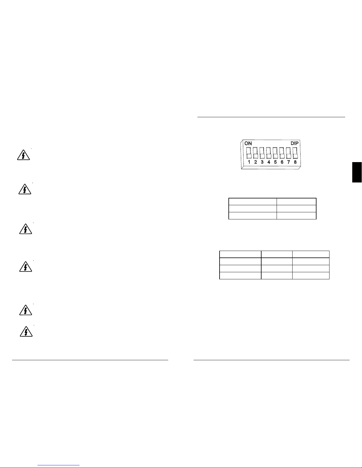
3.2 Configuration
The DIP switch block shown in Figure 3.1 below is used to
set the operating parameters for the ProStar MPPT.
Switch 1: Load / Lighting
Mode Switch 1
Normal OFF
Lighting ON
Switches 2, 3: System Voltage
Three (3) system voltage configurations are available as
shown in the table below:
System Voltage Switch 2 Switch 3
Auto OFF OFF
12 OFF ON
24 ON OFF
NOTE: Before connecting the battery, measure the open-circuit
voltage. It must be over 10 volts to start the controller. If the
system voltage Settings Switches are set to Auto-detect, battery
voltage over 15.5V will be detected as a 24V nominal battery,
and the unit will charge accordingly. The 12/24V auto selection is
only done at start-up, and the detected system voltage will never
change during operation.
Generally, the specfic system voltage is known, and it is best
to set DIPs 2,3 accordingly; the auto-detect setting should
be used only in rare circumstances.
Figure 3.1. DIP Switch Block to set charging parameters
 Loading...