

Morningstar PS-15, PS-30, PS-15M, PS-30M Maintenance Manual

TM
ProStar
Solar Charging System Controller
Installation, Operation, and Maintenance Manual
For the most recent manual revision, see the
version at: www.morningstarcorp.com
www.morningstarcorp.com
MODELS
PS-15
PS-30
PS-15M
PS-30M
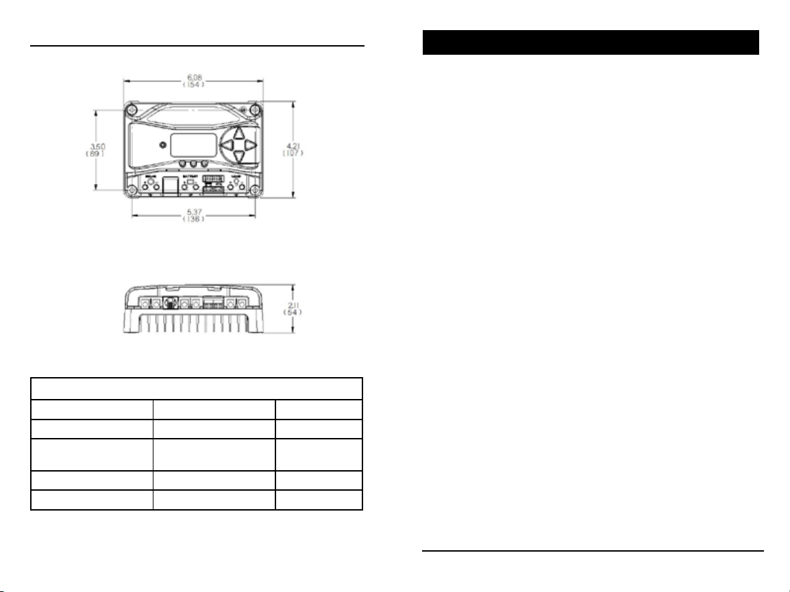
DIMENSIONS [inches (millimeters)]
TABLE OF CONTENTS
SPECIFICATION SUMMARY
PS-15 / PS-15M PS-30 / PS-30M
Nominal Battery voltage 12 / 24V 12 / 24V
Max. PV Open- Circuit
Voltage*
Max. Battery Charging Current 15A 30A
Rated Load Current 15A 30A
30 / 60V 30 / 60V
1.0 Important Safety Instructions
2.0 General Information
2.1 Overview
...........................................................6
.......................................6
2.2 Regulatory Information
2.3 Features
2.4 Optional Accessories
3.0 Installation
.............................................................
.....................................
.....................................................
3.1 General Installation Notes
3.2 Configuration
3.3 Mounting
3.4 Wiring
...................................................... 21
........................................... 16
................................................. 19
...................... ..1
.................................
............................
11
14
14
4.0 Operation.................................................31
4.1 Battery Charging Information.....................31
4.2 Load Control Information...................................43
4.3 LED Indications.................................................. 45
4.3.1 Power-up............................................................45
4.3.2 Status LED..........................................................45
4.3.3 State-of-charge LEDs......................................... 46
4.4 Push-button Use in Non-Metered Versions...... 47
4.5 Custom Settings........ ...................................... 48
4.5.1 Programming with Meter Display..................... 48
4.5.2 Programming in MSView...................................50
Continued
7
9
*Array voltage should never exceed this limit
ProStar Operator’s Manual
iii
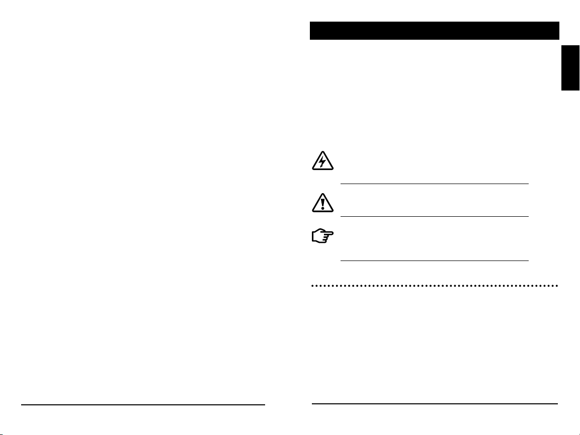
TABLE OF CONTENTS (Cont.)
1.0 IMPORTANT SAFETY INSTRUCTIONS
4.5.3 Meter Display Operation...................................50
4.5.3.1 Directional Key Use and Operation /
Navigating the Meter Map........................... 50
4.5.3.2 Adjusting the Meter Display..........................51
4.5.4 Using the Meter Display to Program Charging
Set-points, Load Control, Communications,
and Advanced Settings................................. 51
4.5.5 Lighting Control - Programming Oveview........51
4.5.6 Lighting Programming Using Meter Display.... 52
4.5.7 Low Temperature Foldback..............................53
4.6 Inspection and Maintenance............................ 54
5.0 Troubleshooting............................................. 56
5.1 Alarms............................................................... 56
5.2 LED Fault Indications........................................ 57
5.3 Battery Charging and Performance Issues.......62
6.0 Warranty and Policies................................... 64
7.0 Technical Specifications................................ 68
Appendix A - De-rating...........................................72
Appendix B - Wire Sizing....................................... 73
Appendix C - Certifications.....................................74
SAVE THESE INSTRUCTIONS.
This manual contains important safety, installation,
operating and maintenance instructions for the ProStar
solar charge controller.
The following symbols are used throughout this manual
to indicate potentially dangerous conditions or mark
important safety instructions:
WARNING: Indicates a potentially dangerous
condition. Use extreme caution when performing
this task.
CAUTION: Indicates a critical procedure for safe
and proper operation of the controller.
NOTE: Indicates a procedure or function that is
important to the safe and proper operation of the
controller.
Safety Information
• Read all of the instructions and cautions in the
manual before beginning installation.
• There are no user serviceable parts inside the
ProStar. Do not disassemble or attempt to repair
the controller.
1.0
iv
ProStar Operator’s ManualImportant Safety Instructions
1
WARNING: Risk Of Electrical Shock.
NO POWER OR ACCESSORY TERMINALS
ARE ELECTRICALLY ISOLATED FROM DC INPUT, AND
MAY BE ENERGIZED WITH HAZARDOUS SOLAR
VOLTAGE. UNDER CERTAIN FAULT CONDITIONS,
BATTERY COULD BECOME OVER-CHARGED. TEST
BETWEEN ALL TERMINALS AND GROUND BEFORE
TOUCHING.
• External solar and battery disconnects are required.
• Disconnect all sources of power to the controller
before installing or adjusting the ProStar.
• There are no fuses or disconnects inside the ProStar
Do not attempt to repair.
Installation Safety Precautions
• Mount the ProStar indoors. Prevent exposure to
the elements and do not allow water to enter the
controller.
• Install the ProStar in a location that prevents casual
contact. The ProStar heatsink can become very hot
during operation.
• Use insulated tools when working with batteries.
• Avoid wearing jewelry during installation.
• The battery bank must be comprised of batteries of
same type, make, and age.
• UL/IEC 62109 certified for use in negative ground or
floating systems only
• Do not smoke near the battery bank.
• Power connections must remain tight to avoid
excessive heating from a loose connection.
• Use properly sized conductors and circuit
interrupters.
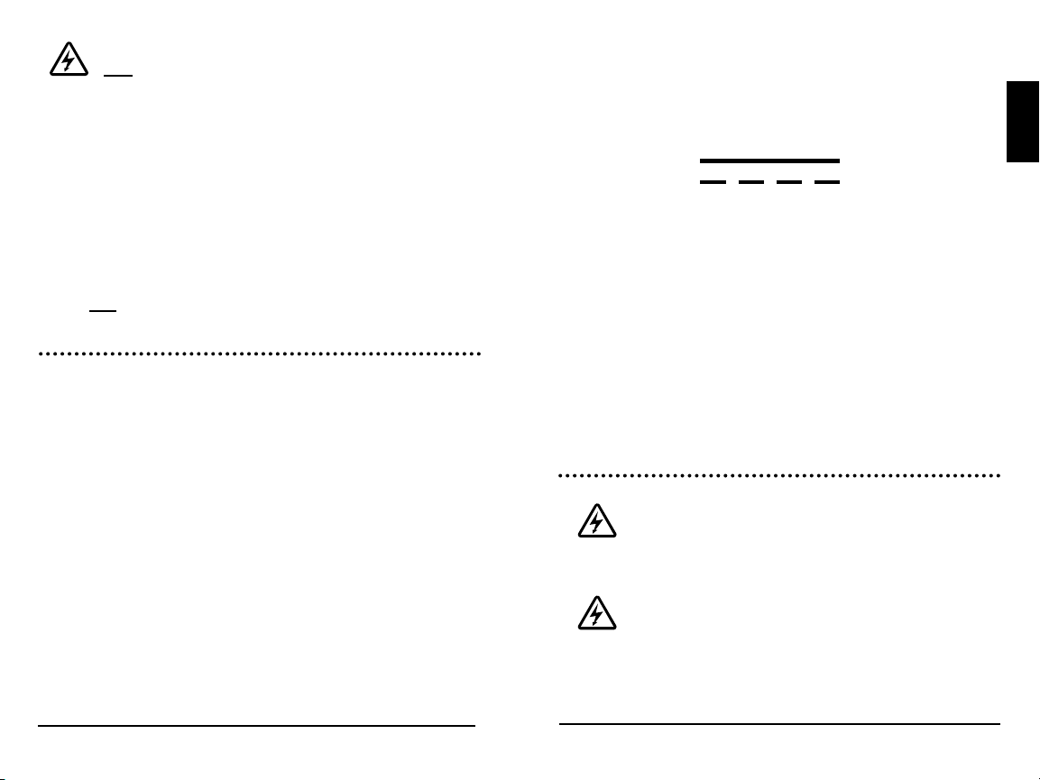
• This charge controller is to be connected to DC
circuits only. These DC connections are identified by
the symbol below:
Direct Current Symbol
The ProStar controller must be installed by a qualified
technician in accordance with the electrical regulations
of the country where the product is installed.
A means of disconnecting all power supply poles must
be provided. These disconnects must be incorporated
in the fixed wiring.
The ProStar negative power terminals are common,
and must be grounded as instructions, local codes,
and regulations require.
Battery Safety
WARNING: A battery can present a risk of
electrical shock or burn from large amounts
of short-circuit current, fire, or explosion from vented
gases. Observe proper precautions.
WARNING: Risk of Explosion.
Proper disposal of batteries is required.
Do not dispose of batteries in fire. Refer to local
regulations or codes for requirements.
1.0
2
ProStar Operator’s ManualImportant Safety Instructions
3

CAUTION: When replacing batteries,
use properly specified number, sizes,
types, and ratings based on application and system
design.
CAUTION: Do not open or mutilate
batteries. Released electrolyte is harmful to
skin, and may be toxic.
Servicing of batteries should be performed, or
supervised, by personnel knowledgeable about
batteries, and the proper safety precautions.
• Be very careful when working with large lead-acid
batteries. Wear eye protection and have fresh water
available in case there is contact with the battery
acid.
• Remove watches, rings, jewelry and other metal
objects before working with batteries.
• Wear rubber gloves and boots
• Use tools with insulated handles and avoid placing
tools or metal objects on top of batteries.
• Disconnect charging source prior to connecting or
disconnecting battery terminals.
• Carefully read the battery manufacturer's
instructions before installing / connecting to, or
removing batteries from, the ProStar.
• Be very careful not to short circuit the cables
connected to the battery.
• Have someone nearby to assist in case of an
accident.
• Explosive battery gases can be present during
charging. Be
release the gases.
• Never smoke in the battery area.
• If battery acid comes into contact with the skin,
wash with
the eye, flood with fresh water and get medical
attention.
• Be sure the battery electrolyte level is correct before
starting charging. Do not attempt to charge a frozen
battery.
• Recycle the battery when it is replaced.
certain there is enough ventilation to
soap and water. If the acid contacts
1.0
4
ProStar Operator’s ManualImportant Safety Instructions
5

2.0
GENERAL INFORMATION
2.2 Regulatory Information
2.1 Overview
Thank you for choosing the ProStar solar charge
controller.
The ProStar battery charging process has been
optimized for long battery life and improved system
performance. Self-diagnostics and electronic error
protections prevent damage when installation
mistakes or system faults occur. The controller also
features eight (8) adjustable settings switches, a
communication port, and terminals for remote battery
temperature and voltage measurement.
Please take the time to read this operator’s manual
to become familiar the many benefits the ProStar can
provide for your PV systems, for example:
• Rated for 12 or 24 Volt systems, and 15 or 30 Amps
of charging current
• Fully protected with automatic and manual recovery
• Seven standard charging programs selectable with
DIP switches
• Continuous self-testing with fault notification
• LED indications and optional meter monitoring
• Terminals sized for #6 AWG /16 mm2 wire
• Includes battery voltage sense terminals
• Optional remote battery temperature sensor
• 5-year warranty (see Section 6.0)
important information on
regulatory requirements.
ProStar controllers comply with the
following European (ENs) standards:
• Immunity: EN61000-6-2:1999
• Emissions: EN55022:1994 with A1 and A3
• Immunity: EN 61000-4-3: 2006
EN 61000- 4-6: 2009
• Emissions: CISPR 22: 2008
FCC Requirements:
This device complies with Part 15 of the
FCC rules. Operation is subject to the
following two conditions: (1) This device
may not cause harmful interference, and,
(2) this device must accept any interference
received, including interference that may
cause undesired operation.
Changes or modifications not expressly
approved by Morningstar, for compliance,
could void the user’s authority to operate
the equipment.
NOTE: This equipment has been tested
NOTE: This section contains
Class B1
and found to comply with the limits for a
Class B digital device, pursuant to Part 15 of the
2.0
6
General Information
ProStar Operator’s Manual
7

FCC rules. These limits are designed to provide
reasonable protection against harmful interference in a
residential installation. This equipment generates, uses,
and can radiate radio frequency energy and, if not
installed and used in accordance with the instruction
manual, may cause harmful interference to radio
communication. However, there is no guarantee that
interference will not occur in a particular installation. If
this equipment does cause harmful interference to radio
or television reception, which can be determined by
turning the equipment on and off, the user is encouraged
to try to correct the interference by one or more of the
following measures:
2.3 Features
The features of the ProStar are shown in Figures 2-1,
2.2 and 2.3 below. An explanation of each feature
follows.
8
1
3
4
11
9
10
2.0
• Re-orient or relocate the receiving antenna.
• Increase the separation between the equipment
and receiver.
• Connect the equipment into an outlet on a
circuit different from that to which the receiver is
connected.
• Consult the dealer, or an experienced radio/TV
technician for help.
This Class B digital apparatus complies with Canadian
ICES-003.
8
General Information
5
6
12
121212
2
13
Figure 2.1. ProStar Features
14
Figure 2.2. Non-Metered
Unit Push-Button
ProStar Operator’s Manual
7
15
Figure 2.3. Removable
Terminal Cover
9

1 - Charging Status / Error LED
Shows charging current and error condition statuses.
2 - Heatsink
Aluminum heatsink (underneath) to dissipate
controller heat (the ProStar is 100% passively cooled
for reliability)
3 - Meter Display (optional)
Digital LCD monitoring and programming display
4 - Battery Status / Fault LED Indicators
Three state of charge (SOC) LED indicators show
charging status and controller faults
5 - Solar Positive and Negative Terminals
Power connections for Solar (+) and (-) cable
terminations
6 - Battery Positive and Negative Terminals
Power connections for Battery (+) and (-) cable
terminations
7 - Load Positive and Negative Terminals
Power connections for Load (+) and (-) cable
terminations
8 - Local Temperature Sensor
Compensates charging based on ambient
temperature, in absence of Remote Temperature
Sensor
9 - Meter Directional Buttons
Used to navigate throughout the meter map
10 - DIP Switches
Eight (8) settings switches to configure operation of
the ProStar
11 - MeterBusTM Port
RJ-11 socket for Morningstar MeterBusTM network
connections
12 - Battery Sense Terminals
Connection points for battery voltage sensing wires
13 - Remote Temperature Sensor Terminals (RTS)
Connection points for a Morningstar RTS to remotely
monitor battery temperature
14 - Push-button (non-metered version)
Initiates manual Equalization, clears any faults or
reminders, conducts a lighting test, restores settings
to factory default
15 - Removable Terminal Cover
Cover protects circuit board and termination points
2.4 Optional Accessories
The following accessories are available for purchase
separately from your authorized Morningstar dealer:
Remote Temperature Sensor (Model: RTS)
The RTS measures battery temperature for accurate
temperature compensation and is recommended
when the ambient battery temperature differs from the
ambient controller temperature by +/- 5º C or more.
An RTS can be attached to the ProStar at any time.
The ProStar will automatically use the RTS for battery
temperature compensation when installed. The stan
dard cable length is 33 ft (10m), and can be extended
to 100 ft (30m) if required. Installation instructions are
provided with the RTS.
-
2.0
10
General Information
ProStar Operator’s Manual
11

NOTE: The use of a Remote Temperature
Sensor (RTS) is strongly recommended.
Controller location, air flow, and system power can
drastically affect the local temperature sensor reading.
An RTS will provide optimal charging performance.
RM-1 Meter
A remote meter for monitoring system variables,
for use through the ProStar Meterbus port.
RelayDriver (RD-1)
The Relay DriverTM accessory enables the ProStar
to control external devices. Four (4) relay control
ports can be configured (in various combinations) to
perform the following tasks:
• generator control (2, 3, and 4-wire configurations)
• dry contacts for alarms and other signals
• advanced load control
• vent fan control
• DIN rail compatible or surface mount
For more information on the Relay Driver, visit our
website at www.morningstarcorp.com, or inquire with
your local Morningstar dealer.
Ground-fault Protection Device (GFPD-150V)
The GFPD-150V detects power source ground faults
and interrupts current as required by the US National
Electrical Code.
Communications Support:
Ethernet MeterBus Converter (EMC-1)
This product is an Ethernet gateway that provides
web monitoring services, a Modbus TCP/IP server,
and a local web page server. End users can collect
information about their off-grid PV system remotely.
One EMC-1 supports all products with MeterBus
ports by bridging MODBUS TCP/IP requests to serve
LiveView pages for each product.
USB Communications Adapter (UMC-1)
A modular unit that uses a USB-B plug, usually
from a USB A-B computer cable, and an RJ-11
plug to connect with a Morningstar controller’s
MeterBus port, for monitoring and programming
using MSView PC software.
TM
PC MeterBus Adapter
(Model: MSC)
The MSC converts the MeterBus RJ-11 electrical
interface to an isolated standard RS-232 interface
which enables communication between the
ProStar and a PC.
The MSC can be used for
programming custom charging set-points, and for
logging data in MSView. See Section 4.5 for more
information on programming.
2.0
12
General Information
ProStar Operator’s Manual
13
3.0 INSTALLATION INSTRUCTIONS
3.1 General Installation Notes
• Read through the entire installation section first
before beginning installation.
• Do not install in locations where water can enter
the controller.
• Loose power connections and/or corroded wires
may result in resistive connections that melt wire
insulation, burn surrounding materials, or even
cause fire. Ensure tight connections and use cable
clamps to secure cables and prevent them from
swaying in mobile applications.
• Preset charging profiles are generally designed for
lead acid batteries. Custom settings can be used
for varied charging requirements (see sections 3.2
and 4.5 for details). Note that some battery types
may not be compatible.
• The ProStar battery connection may be wired to
one battery or a bank of batteries. The following
instructions refer to a singular battery, but it is
implied that the battery connection can be made
to either one battery or a group of batteries in a
battery bank.
• The ProStar uses stainless steel fasteners, an
anodized aluminum heat sink, and conformal
coating to protect it from harsh conditions.
However, for acceptable service life, extreme
temperatures and marine environments should be
avoided.
• The ProStar prevents reverse current leakage at
night, so a blocking diode is not required in the
system.
• The ProStar is designed to regulate ONLY solar
(photovoltaic) power. Connection to any other type
of power source e.g. wind turbine or generator may
void the warranty. However, other power sources
may be connected directly to the battery.
• The connector terminals will accept a maximum
wire size of AWG #6 / 16 mm2 (solid/multi-strand)
or #8 AWG / 10 mm
flathead screwdriver, and torque tightly up to 35
in-lb.
• Stranded wires to be connected to the ProStar
terminals should be prepared first with e.g.
clamped copper heads, etc. to avoid the
possibility of conductor strands coming free out of
the connection screw, and possible contact with the
metal enclosure.
WARNING: Solar and battery fuses or DC
breakers are required in the system. These
protection devices are external to the ProStar
controller, and must be a maximum of 20 Amps for the
ProStar-15/M, and 50 Amps for the ProStar-30/M.
WARNING: All breakers must be properly
rated for wire ampacity, which may require
less than the maximum breaker sizes referenced
above.
2
(fine strand). Use an insulated
3.0
14
Installation
ProStar Operator’s Manual
15
WARNING: Minimum over-current
protection device interrupt ratings must be
2000A for 12V systems, and 4000A for 24V systems.
NOTE: Carefully observe the LEDs after
each connection. The LEDs will indicate
proper polarity, and a secure co nnection.
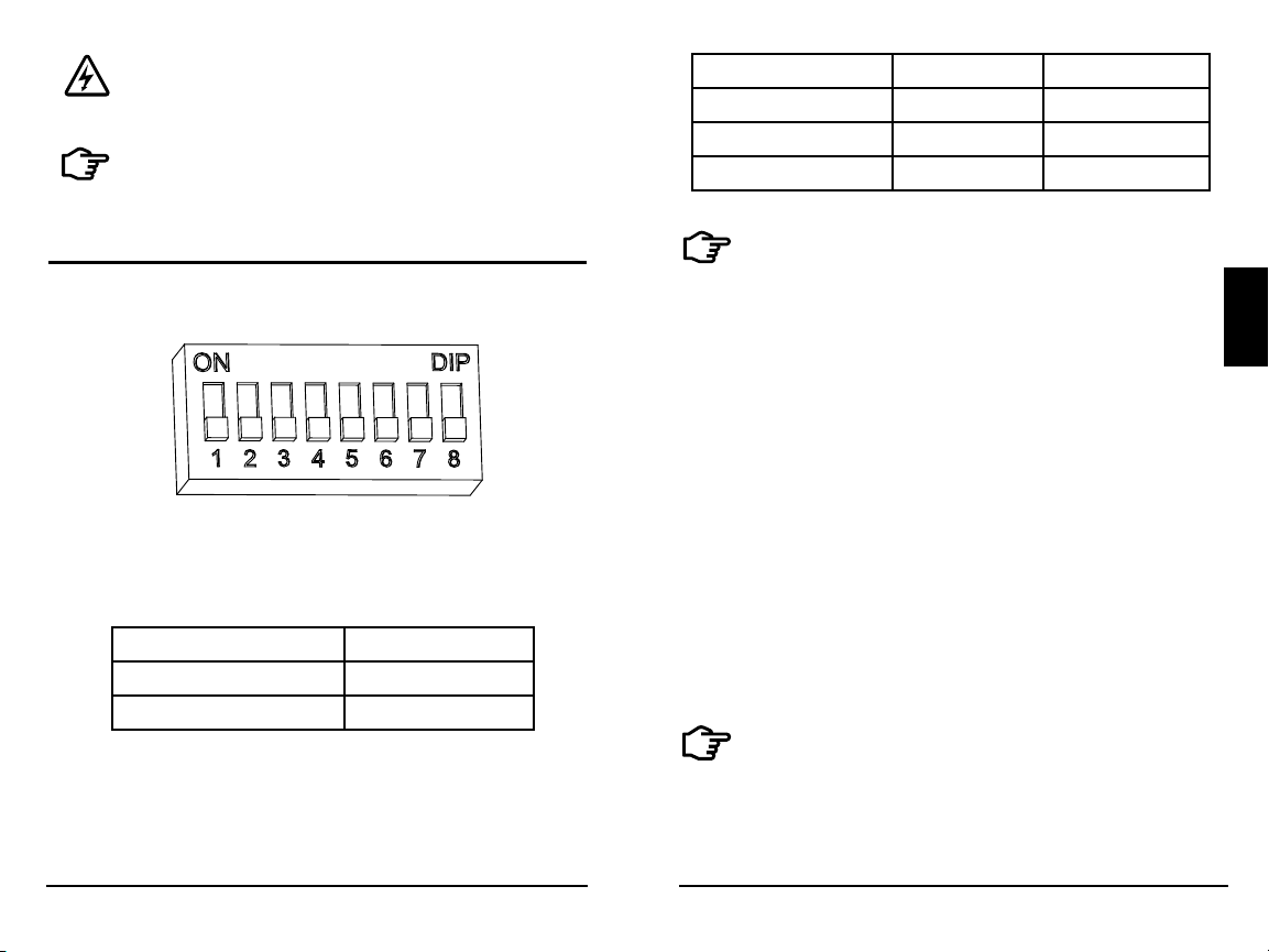
System voltage Switch 2 Switch 3
Auto OFF OFF
12 OFF ON
24 ON OFF
3.2 Configuration
The DIP switch block shown in Figure 3.1 below is
used to set the operating parameters for the ProStar.
Figure 3.1. DIP Switch Block to set charging parameters
Switch 1: Load / Lighting
Mode Switch 1
Normal OFF
Lighting ON
Switches 2, 3: System Voltage
Three (3) system voltage configurations are available
as shown in the table below:
NOTE: Before connecting the battery, measure
the open-circuit voltage. It must be over 10
Volts to start the controller. If the system voltage
DIP Settings Switches are set to Auto-detect, battery
voltage over 15.5V will be detected as a 24V nominal
battery, and the unit will charge accordingly. The
12/24V auto selection is only done at start-up, and
the detected system voltage will never change during
operation.
It is recommended to set DIPs 2 and 3 to the correct
system voltage setting. Only use the default autodetect setting if the nominal system voltage is not
known.
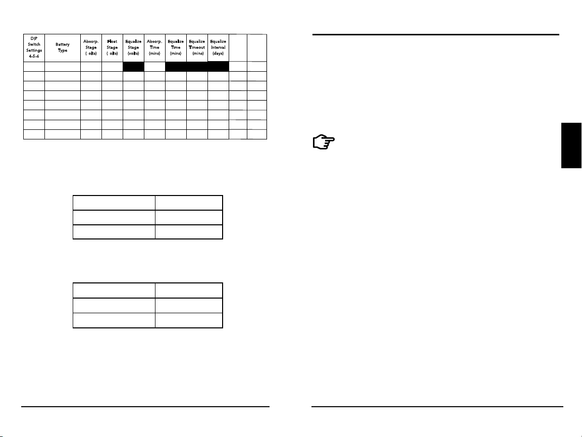
Switches 4, 5, 6: Battery Type Selection
Preset ProStar battery charging options are shown
in table 3-1 below. All voltage settings listed are for
nominal 12 Volt batteries. Multiply the voltage settings
by two (2) for 24 Volt systems.
NOTE: The charging profiles below are general
guidelines for use at the operator’s discretion. Consult
the battery manufacturer for optimal battery charge
settings.
3.0
16
Installation
ProStar Operator’s Manual
17
DIP
Equaliz e
Equaliz e
Equaliz e
Interva l
(days)
Equaliz e
Interva l
(days)
Custom Custom
Custom
B
witch
etting s
-5-6
4
attery
ype
T
S
S
off-off-off 1 - Sealed* 14.00 13.50
off-off-on 2 - Sealed* 14.15 13.50 14.40 150 60 120 28
off-on-off 3 - Sealed* 14.30 13.50 14.60 150 60 120 28
off-on-on 4- AGM/Flooded 14.40 13.50 15.1 0 180 120 180 28
on-off-off 5 - Flooded 14.60 13.50 15.30 180 120 180 28
on-off-on 6 - Flooded 14.70 13.50 15.40 180 180 240 28
on-on-off 7 - L-16 15.40 13.40 16.0 0 180 180 240 14
on-on-on 8 - Custom Custom Custom Custom Custom Custom Custom Custom
* “Sealed” baery type includes gel and AGM baeries
A
bsorp.
S
volts)
(
tage
F
S
volts)
(
loat
tage
E
qualiz e
tage
S
volts)
(
A
(
bsorp.
ime
T
mins)
150
E
E
qualiz e
qualiz e
ime
imeout
T
T
mins)
mins)
(
(
E
qualiz e
nterval
I
(
days)
LVD
(volts)
11.50
11.30
11.50
11.70
11.90
12.10 13.60
12.30
Custom
LVR
(volts)
12.60
12.80
13.00
13.20
13.40
13.80
Custom
Table 3.1. Battery charging settings for each selectable battery type
Switch 7: Battery Equalization
Mode Switch 7
Manual Equalization OFF
Auto Equalization ON
Switch 8: Current Switching
Mode Switch 8
PWM switching OFF
Slow switching ON
3.3 Mounting
Inspect the controller for shipping damage. Mount the
ProStar to a vertical surface (4-#8 stainless steel selftapping screws are included). Tighten the mounting
screws using care not to crack the plastic case. Do not
install directly over an easily combustible surface since
the heat sink may get hot under certain operating
conditions.
NOTE: The heat sink must be in a vertical
position (fins up and down).
For proper air flow, allow at least 15 cm (6 in) of space
above and below the controller, and 50 mm (2 in) at
the sides - see Figure 3-2 below. Install in an area
protected from direct rain and direct sun.
If the controller is installed in an enclosure, some
ventilation is recommended. Do not locate in an
enclosure where battery gases can accumulate.
3.0
The default (PWM) switching setting (OFF / down) operates
at 300Hz. If load or system noise is an issue, DIP 8 can be set
(ON-up) for slow switching at 1Hz. Standard PWM switching is
recommended when system noise is not a problem.
18
Installation
ProStar Operator’s Manual
19
 Loading...