

Morningstar EMC-1 Installation Manual

(
TM
EMC-1
Ethernet-Meterbus Converter
Installation and Operation Manual
DIMENSIONS [inches (millimeters)]
4.85
( 123 )
For the most recent manual revisions, see the
version at: www.morningstarcorp.com
www.morningstarcorp.com
3.37
86 )
5.51
( 140 )
6.04
( 153 )
SPECIFICATION SUMMARY
EMC-1 SPECIFICATION
Required Power Source
Required Power Supply
Connection
Input Voltage 8-80 Vdc
Ethernet Speed 10/100Base-T
System battery for Morningstar
Device, or AC-DC converter
On-board terminals
1.20
( 30 )
2.17
( 55 )

TABLE OF CONTENTS
TABLE OF CONTENTS (Cont.)
1.0 General Information........................................... 1
1.1 Overview.............................................................1
1.2 Features..............................................................3
2.0 Installation...........................................................4
2.1 Mounting............................................................4
2.2 Configuration......................................................5
2.3 Connections....................................................... 6
2.3.1 Installing the EMC-1.......................................... 6
2.3.2 TriStar and TriStar MPPT Installation Using a
Y-cable Adaptor................................................... 6
2.3.3 TriStar with Meter Application............................. 7
2.4 DIP Switch Set-up..............................................7
2.4.1 Ethernet Writes.................................................. 8
2.5 Connecting the Power Wires............................ 9
3.0 Operation...........................................................10
3.1 LED Indicators....................................... ..........10
3.2 Start-up............................................................10
3.3 EMC-1 Status LEDs..........................................11
3.4 Ethernet Write LED......................................... 12
3.5 Connectivity..................................................... 12
3.5.1 MSView............................................................ 12
3.5.2 LiveView Web Pages........................................13
3.5.3 Connecting to a LAN / WAN...........................15
3.5.4 Connecting to the EMC-1 from a Remote
Location...........................................................15
3.6 Push-button Functions.....................................16
3.6.1 Factory Reset................................................... 16
3.6.2 To Recover from a Failed Firmware
Update............................................................ 16
3.7 Simple Network Management Protocol
(SNMP)...............................................................17
3.7.1 SNMP Troubleshooting......................................19
4.0 Troubleshooting................................................20
4.1 Faults and Corrections.......................................20
5.0 Warranty..................................................... .22
6.0 Technical Specifications.................................... 24
7.0 Certifications.....................................................25

1.0 GENERAL INFORMATION
1.1 Overview
The EMC-1 is a MODBUSTM Ethernet to Meterbus
converter that bridges a TCP/IP connection to a
Morningstar charge controller or inverter (Morningstar
Device) not having built-in Ethernet connectivity. The
connected device needs to have a Meterbus (RJ-11)
port.
The EMC-1 acts as an Ethernet gateway that serves
MODBUS IP and local Web pages. Ethernet networks
also include local area networks (LANs) and Internet
communications.
The EMC-1 supports the following communication
capabilities with a Morningstar Device:
• Morningstar LiveViewTM Internet Web monitoring
and Network settings changes;
• Monitoring, logging and custom programming
using Morningstar MSView
TM
PC software;
TM
The table below lists products supported by the
EMC-1, and includes port and data details. For a
current list, see the latest manual version at:
www.morningstarcorp.com
Product
ProStar Gen 3 Yes No Yes
PS-MPPT-25/M Yes No Yes
PS-MPPT-40/M Yes No Ye s
SunSaver Duo Yes No No
SunSaverMPPT-15L
SureSine-300
(all models)
TS-45* No Yes Ye s
TS-60* No Yes Ye s
TS-MPPT-30* No Yes Ye s
TS-MPPT-45* No Yes Ye s
TS-MPPT-60* No Yes Ye s
* The EMC-1 included Y-cable is required to draw power from
the RJ-11 port while communicating via the RS-232 port. See
Section 2.3.2.
Modbus via
RJ-11
Yes No Yes
Yes No No
RS-232 Port
Logs Historical
Data
Table 1-1. Supported Products
-1- -2-
1.2 Features
5
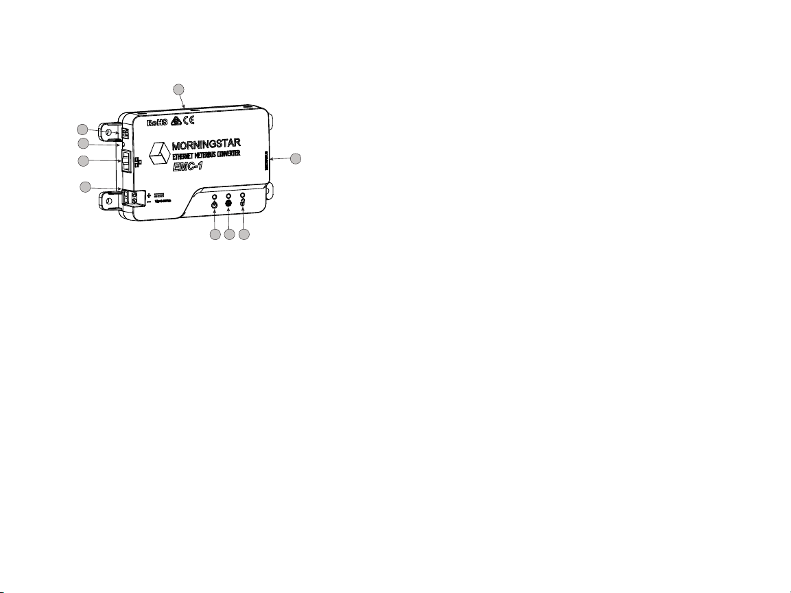
The features of the EMC-1 are shown in Figure 1-1
below. An explanation of each feature follows.
1
2
3
4
9
8
2.0 INSTALLATION
2.1 Mounting
The EMC-1 can be wall-mounted, surface-mounted or
DIN rail mounted using basic tools:
Flat head screw driver
Philips head screw driver
Drill (if wall or surface mounting)
1/8” drill bit (if wall or surface mounting)
6 7
5
Figure 1-1 EMC-1 Features
1 - DIP Switches
DIP 1 enables Ethernet write commands
DIP 2 NOT USED
2 - Reset Button
Used for factory reset or firmware failure
3 - Ethernet port (RJ-45)
Used to connect the EMC-1 to LAN / Internet
4 - Power Input
8-80 Vdc power input
5 - Status LED
Green and red lights indicate unit status
6 - Green/red LED - NOT USED
7 - Ethernet Write LED
Green light indicates Ethernet write command capability
8 - Meterbus (RJ-11 port)
Used to connect the EMC-1 to Morningstar Device
9 - DIN rail mounts (bottom of unit)
35mm standard size
-3-
Option 1 - Wall and Surface Mounting:
Step 1
Locate the EMC-1 on a surface that is protected from
direct sun, high temperatures, corrosive fumes, and water.
Do not install in a confined area where battery gases can
accumulate.
Step 2
Before starting the installation, place the EMC-1 on the
surface where it will be mounted and determine where the
wires will enter and exit. Be sure there is sufficient bending
room for the wires and communication cables. If possible,
verify that the mounting screws will not penetrate wires or
other objects located on the opposite side of the surface.
Step 3
Place the EMC-1 on the intended mounting surface, mark
four holes for drilling. Remove the EMC-1 from the
surface, and using a 1/8” bit, drill pilot holes for each of
the four mounting screws, as indicated on the surface.
-4-
Step 4
Place the EMC-1 onto the surface and align the mounting
feet holes with the four pilot holes. Use the included #10
screws to secure the EMC-1 to the surface.
Option 2 - DIN Rail Mounting:
The EMC-1 will also mount to standard 1-3/8” (35mm) DIN
rail.
Step 1
Choose the DIN rail mounting location. It should be
protected from direct sun, high temperatures, corrosive
fumes, and water. Do not install the EMC-1 in a confined
area where battery gases can accumulate.
Step 2
Confirm sufficient space above and below the DIN rail
mounting location for EMC-1 cable connections
. Using
screws, secure the DIN rail to the desired surface.
Step 3
The EMC-1 is designed for tool-less installation onto a DIN
rail. There are four hooks on the bottom of the EMC-1
that slide over the upper and lower lips of the DIN rail.
2.2 Configuration
For communication via the EMC-1, the Morningstar
Device’s DIP switches, if applicable, must be set for
MODBUS communication. The SunSaver MPPT,
ProStar MPPT, and the SureSine products need to
have the appropriate DIP switch set for MODBUS
communication. See Section 2.4 for EMC-1 DIP switch
settings.
2.3 Connections
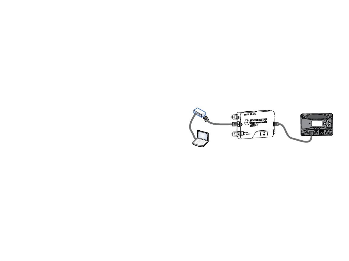
2.3.1 Installing the EMC-1
NOTE: Make COM connections with no power applied
Insert an Ethernet cable (A) into the RJ-45 jack of the
EMC-1. Insert the plug on one end of a six-conductor
RJ-11 cable (B) into the RJ-11 jack on the EMC-1.
Insert the plug on the other end of the RJ-11 cable
into the RJ-11 port of the Morningstar Device. See
the Operation section (3) for details on the start-up
procedure.
A
RJ-45
NOTE: Make COM connections
with no power applied
Figure 2-1. Connecting the COM cables
B
RJ-11
2.3.2 TriStar and TriStar MPPT Installation Using a
Y-cable Adaptor
To communicate with the EMC-1, TriStar and TriStar
MPPT controllers must be installed using the included
Y-cable adapter. The RS-232 serial and RJ-11 plugs are
connected at the controller, and the other RJ-11 plug
at the EMC-1.
-5- -6-
 Loading...