

Morningstar EC-10, EC-20M, EC-10M, EC-30M, EC-30 Maintance Manual
...
Solar Charging System Controller
Installation, Operation, and Maintenance Manual
Languages: English, French, German, Spanish
www.morningstarcorp.com
EcoPulse
TM
MODELS
EC-10
EC-10M
EC-20
EC-20M
EC-30
EC-30M
For the most recent manual revisions, see the
version at: www.morningstarcorp.com

ii
TABLE OF CONTENTS
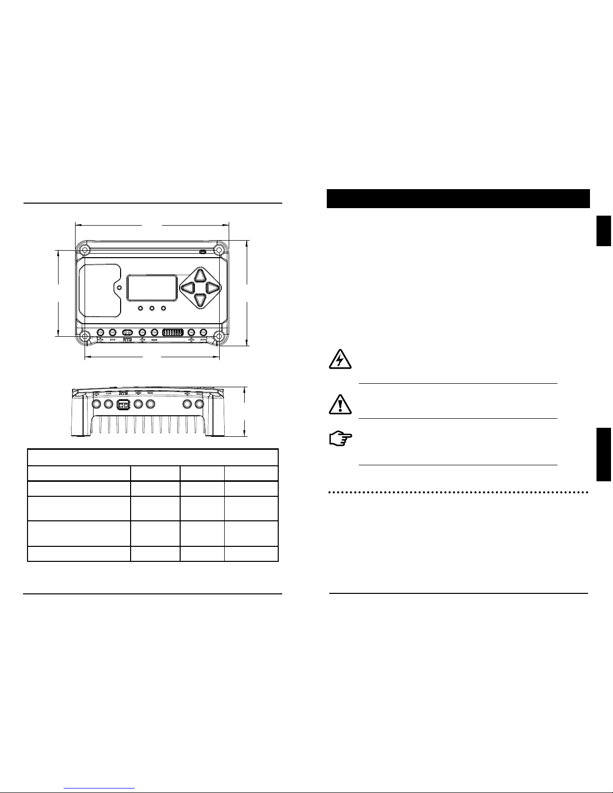
6.30
160
4.33
110
5.51
140
3.54
90
2.04
52
DIMENSIONS [inches (millimeters)]
1.0 Important Safety Instructions.............................1
2.0 General Information......................................... ..6
2.2 Features
...............................................................6
2.3 Optional Accessories
............................................7
3.0 Installation..........................................................8
3.1 General Installation Notes.....................................8
3.2 Configuration
...............................................................9
3.3 Mounting
....................................................................11
3.4 Wiring
.........................................................................13
3.5 Custom Settings
....................................................... 19
3.5.1 Adjusting the Meter Display
....................................19
3.5.2
Directional Key Use and Operation /
Navigating the Meter Map
..................................... 19
3.5.3 Using the Meter Display to Program Charging
Set-points and Load Control......................................19
4.0 Operation.........................................................20
4.1 Battery Charging Information........................ .....20
4.2 Load Information.........................................................22
4.3 LED Indcations............................................................ 22
4.3.1 Power-up.....................................................................22
4.3.2 Status LED...................................................................23
4.3.3 State-of-charge LEDs................................................. 23
Continued
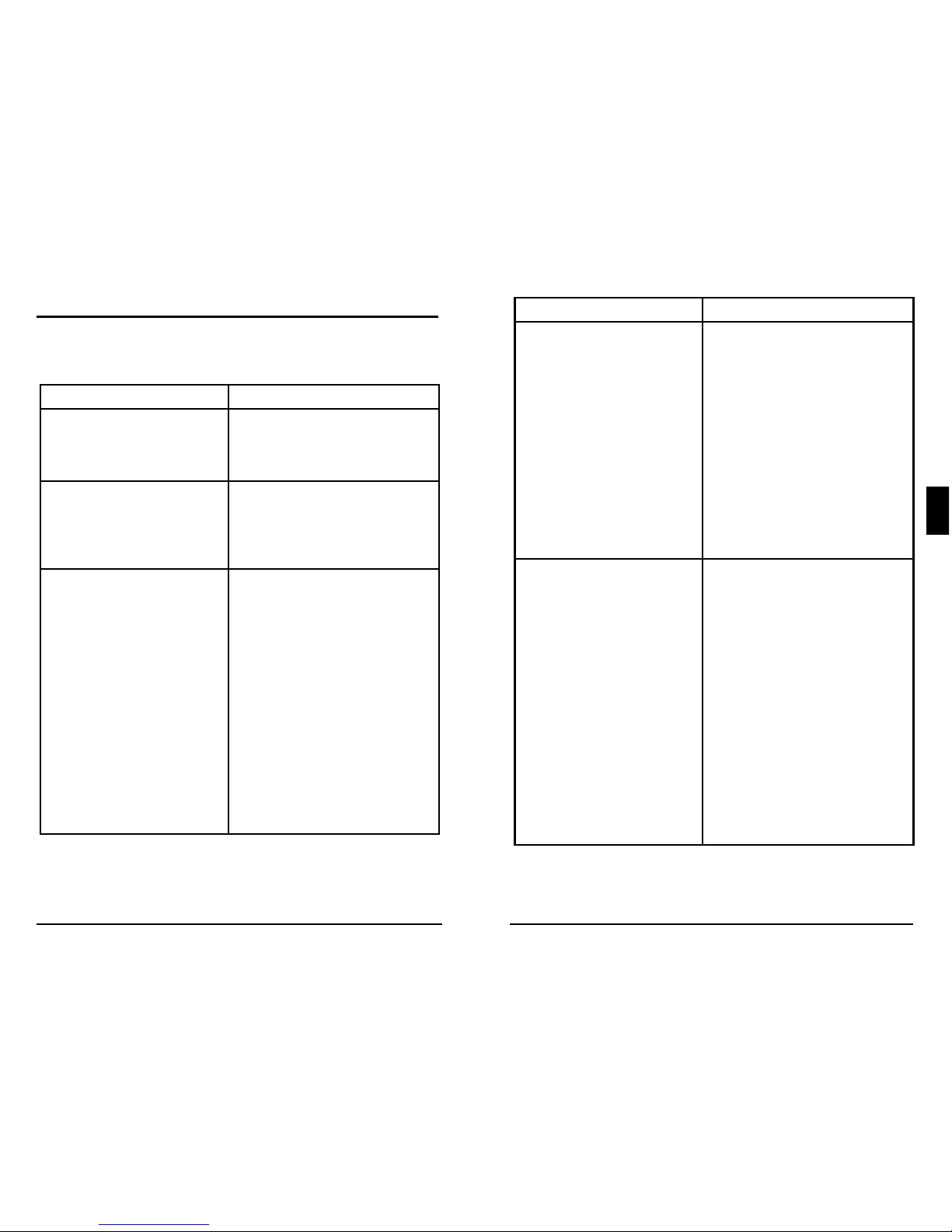
SPECIFICATION SUMMARY
10/M 20/M 30/M
Nominal Battery voltage 12 / 24V 12 / 24V 12 / 24V
Max. PV Open- Circuit Voltage* 60V 60V 60V
Max. Battery Charging Current 10A 20A 30A
Rated Load Current 10A 20A 30A
* Array voltage should never exceed this limit
1
iv
EcoPulse Operator’s ManualImportant Safety Instructions
1.0
TABLE OF CONTENTS (Cont.)
4.4
Protections, Faults & Alarms................................. 24
4.4.1 Protections...................................................................24
4.4.2 LED Fault Indication.....................................................24
4.4.3 Alarms..........................................................................25
4.5 Inspection and Maintenance............................. ..........26
5.0 Warranty.................................................................28
6.0 Technical Specifications......................................... 29
Appendix - Certifications.................................................30
SAVE THESE INSTRUCTIONS.
This manual contains important safety, installation,
operating and maintenance instructions for the EcoPulse
solar charge controller.
The following symbols are used throughout this manual
to indicate potentially dangerous conditions or mark
important safety instructions:
WARNING: Indicates a potentially dangerous
condition. Use extreme caution when performing
this task.
CAUTION: Indicates a critical procedure for safe
and proper operation of the controller.
NOTE: Indicates a procedure or function that is
important to the safe and proper operation of the
controller.
Safety Information
• Read all of the instructions and cautions in the
manual before beginning installation.
• There are no user serviceable parts inside the
EcoPulse. Do not disassemble or attempt to repair
the controller.
1.0 IMPORTANT SAFETY INSTRUCTIONS
3
2
EcoPulse Operator’s ManualImportant Safety Instructions
1.0
• Use properly sized conductors and circuit
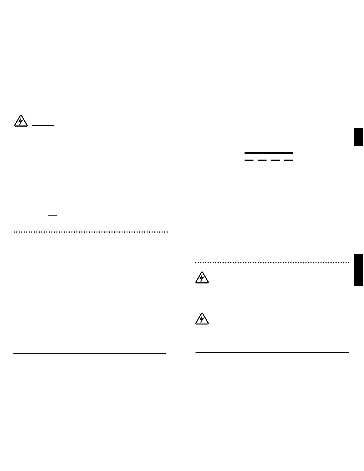
interrupters.
• This charge controller is to be connected to DC
circuits only. These DC connections are identified by
the symbol below:
Direct Current Symbol
The EcoPulse controller must be installed by a qualified
technician in accordance with the electrical regulations
of the country where the product is installed.
A means of disconnecting all power supply poles must
be provided. These disconnects must be incorporated
in the fixed wiring.
The EcoPulse negative power terminals are common,
and must be grounded as instructions, local codes,
and regulations require.
Battery Safety
WARNING: A battery can present a risk of
electrical shock or burn from large amounts
of short-circuit current, fire, or explosion from
vented gases. Observe proper precautions.
WARNING: Risk of Explosion.
Proper disposal of batteries is required. Do
not dispose of batteries in fire. Refer to local
regulations or codes for requirements.
WARNING: Risk Of Electrical Shock.
NO POWER OR ACCESSORY TERMINALS ARE
ELECTRICALLY ISOLATED FROM DC INPUT,
AND MAY BE ENERGIZED WITH HAZARDOUS
SOLAR VOLTAGE. UNDER CERTAIN FAULT
CONDITIONS, BATTERY COULD BECOME OVERCHARGED. TEST BETWEEN ALL TERMINALS AND
GROUND BEFORE TOUCHING.
• External solar and battery disconnects are required.
• Disconnect all sources of power to the controller
before installing or adjusting the EcoPulse.
• There are no fuses or disconnects inside the
EcoPulse Do not attempt to repair.
Installation Safety Precautions
• Mount the EcoPulse indoors. Prevent exposure to
the elements and do not allow water to enter the
controller.
• Install the EcoPulse in a location that prevents
casual contact. The EcoPulse heatsink can become
very hot during operation.
• Use insulated tools when working with batteries.
• Avoid wearing jewelry during installation.
• The battery bank must be comprised of batteries of
same type, make, and age.
• UL/IEC 62109 certified for use in negative ground or
floating systems only
• Do not smoke near the battery bank.
• Power connections must remain tight to avoid
excessive heating from a loose connection.
5
4
EcoPulse Operator’s ManualImportant Safety Instructions
1.0
CAUTION: When replacing batteries, use
properly specified number, sizes, types, and
ratings based on application and system
design.
WARNING: Do not open or mutilate
batteries. Released electrolyte is harmful
to skin, and may be toxic.
Servicing of batteries should be performed, or
supervised, by personnel knowledgeable about
batteries, and the proper safety precautions.
• Be very careful when working with large lead-acid
batteries. Wear eye protection and have fresh water
available in case there is contact with the battery
acid.
• Remove watches, rings, jewelry and other metal
objects before working with batteries.
• Wear rubber gloves and boots
• Use tools with insulated handles and avoid placing
tools or metal objects on top of batteries.
• Disconnect charging source prior to connecting or
disconnecting battery terminals.
• Carefully read the battery manufacturer's
instructions before installing / connecting to, or
removing batteries from, the EcoPulse.
• Be very careful not to short circuit the cables
connected to the battery.
• Have someone nearby to assist in case of an
accident.
• Explosive battery gases can be present during
charging. Be
certain there is enough ventilation to
release the gases.
• Never smoke in the battery area.
• If battery acid comes into contact with the skin,
wash with
soap and water. If the acid contacts
the eye, flood with fresh water and get medical
attention.
• Be sure the battery electrolyte level is correct before
starting charging. Do not attempt to charge a frozen
battery.
• Recycle the battery when it is replaced.
General Information
EcoPulse Operator’s Manual
7
6
2.0
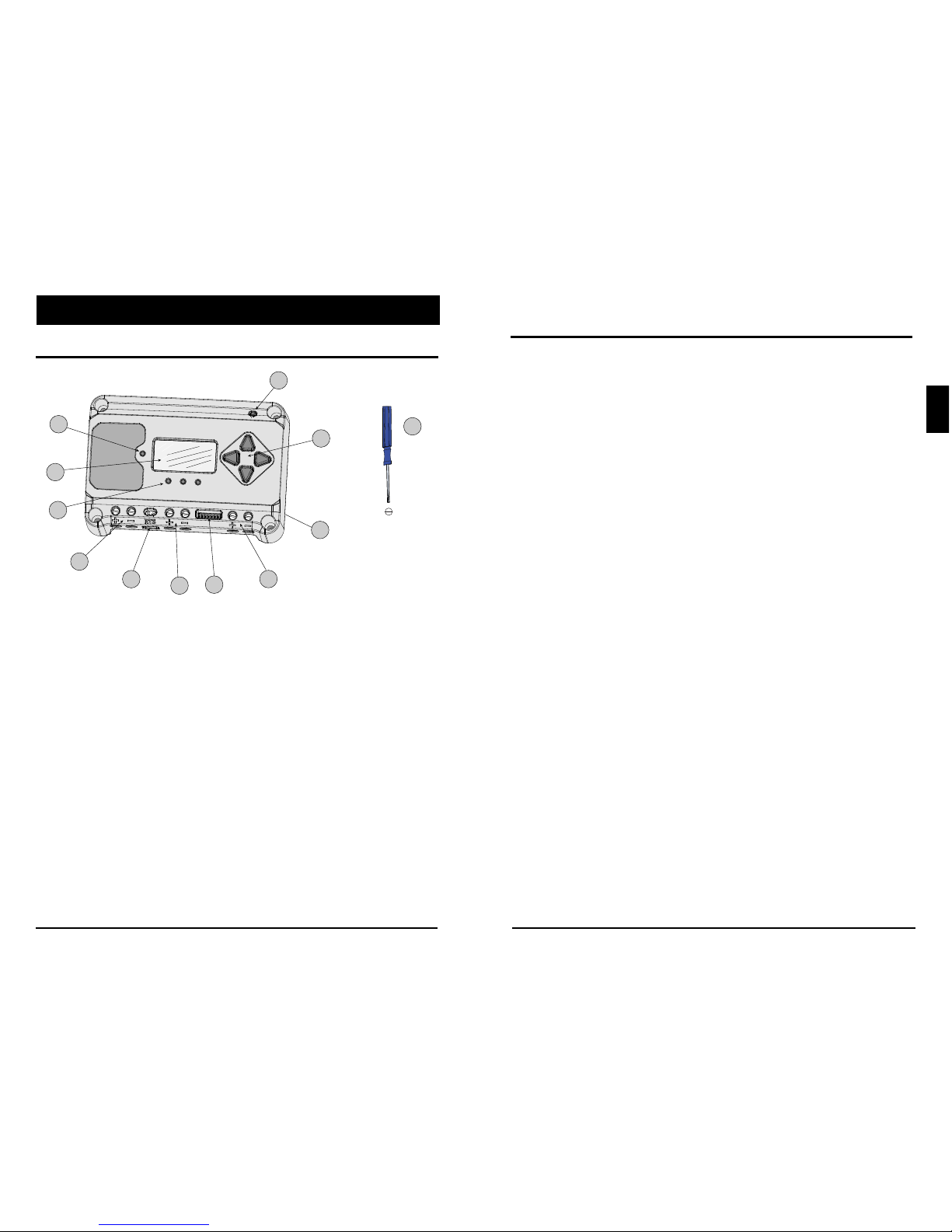
2.1 Features
1 - Charging Status / Error LED
2 - Meter Display (optional)
3 - Battery Status / Fault LED Indicators
4 - Solar Positive and Negative Terminals
5 - Remote Temperature Sensor Terminals (RTS)
6 - Battery Positive and Negative Terminals
7 - DIP Switches
8 - Load Positive and Negative Terminals
9 - Heatsink
10 - Meter Directional Buttons
11 - Local Temperature Sensor
12 - Mini-screwdriver for DIP switch adjustments
and RTS screws
2.0
GENERAL INFORMATION
Figure 2.1. EcoPulse Features
1
2
3
7
8
9
4
5
6
10
12
11
2.2 Optional Accessories
The following accessory is available for purchase
separately from your authorized Morningstar dealer:
Remote Temperature Sensor (Model: RTS)
The RTS measures battery temperature for accurate
temperature compensation, and is recommended
when the ambient battery temperature differs from the
ambient controller temperature by +/- 5ºC or more.
When installed, the EcoPulse will automatically use the
RTS for battery temperature compensation.

Installation
EcoPulse Operator’s Manual
9
8
3.0
3.0 INSTALLATION
3.1 General Installation Notes
• Read through the entire installation section first
before beginning installation.
• Do not install in locations where water can enter
the controller.
• Loose power connections and/or corroded wires
may result in resistive connections that melt wire
insulation, burn surrounding materials, or even
cause fire. Ensure tight connections.
• F
or good service life, extreme temperatures and
marine environments should be avoided.
WARNING: Solar and battery fuses or DC
breakers are required in the system. These
protection devices are external to the EcoPulse
controller, and must be a maximum of 15
Amps for the EcoPulse-10/M, 30 Amps for
the EcoPulse-20/M, and 40 Amps for the
EcoPulse-30/M.
WARNING: All breakers must be properly rated
for wire ampacity, which may require less than
the maximum breaker sizes referenced above.
WARNING: Minimum over-current protection
device interrupt ratings must be 2000A
for 12V systems, and 4000A for 24V systems.
NOTE: Carefully observe the LEDs after
each connection. The LEDs will indcate
proper polarity, and a secure co nnection.
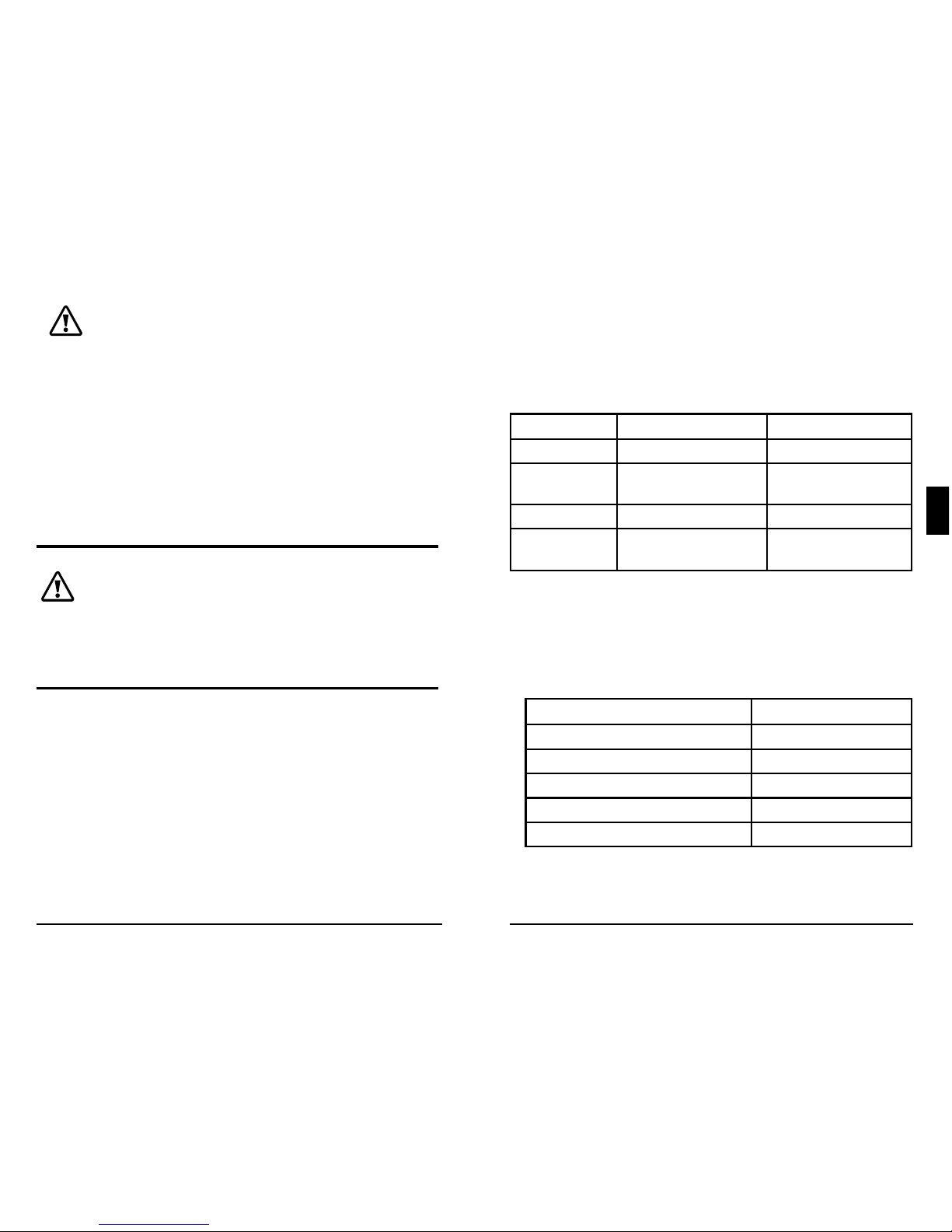
3.2 Configuration
The DIP switch block shown below is used to set the
operating parameters for the EcoPulse.
Switch 1: Lighting Control
With DIP 1 ON, a light connected to the load
terminals will be ON from dusk-dawn.
Switches 2, 3: System Voltage
Three (3) system voltage configurations are available
as shown in the table below:
System Voltage Switch 2 Switch 3
Auto OFF OFF
12 OFF ON
24 ON OFF
NOTE: Before connecting the battery, measure
the open-circuit voltage. It must be over 10 Volts
tostart the controller. (Cont.)
Installation
EcoPulse Operator’s Manual
11
10
3.0
Switch 7: Battery Equalization
Mode Switch 7
Manual Equalization OFF
Auto Equalization ON
NOTE: Regardless of DIP 7 setting, manual EQ can be initiated using
the on-board meter command, "Start Equalize". For non-meter
versions, DIP 7 only enables or disables auto equalization - manual EQ
is not available.
Switch 8: Current Switching
Mode Switch 8
PWM switching OFF
Slow switching ON
The default (PWM) switching setting (OFF / down) operates
at 300Hz. If load or system noise is an issue, DIP 8 can be set
(ON-up) for slow switching at 1Hz. Standard PWM switching is
recommended when system noise is not a problem.
3.3 Mounting
Inspect the controller for shipping damage. Mount
the EcoPulse to a vertical surface (4-#8 stainless steel
self-tapping screws are included). Tighten the mounting
screws using care not to crack the plastic case. Do not
install directly over an easily combustible surface since
the heat sink may get hot under certain operating
conditions.
NOTE: The heat sink must be in a vertical
position (fins up and down).
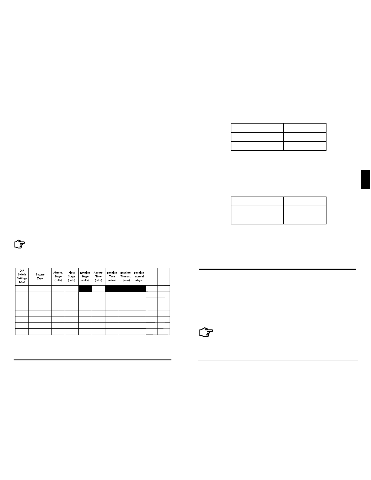
Table 3.1. Battery charging settings for each selectable battery type
If the system voltage DIP Settings Switches are set
to Auto-detect, battery voltage over 15.5V will be
detected as a 24V nominal battery, and the unit will
charge accordingly.
The 12/24V auto selection is done only at start-up,
and the detected system voltage will never change
during operation. It is recommended to set DIPs 2
and 3 to the correct system voltage setting. Only use
the default auto-detect setting if the nominal system
voltage is not known.
Switches 4, 5, 6: Battery Type Selection
Preset EcoPulse battery charging options are shown
in table 3-1 below. All voltage settings listed are
for nominal 12 Volt batteries. Multiply the voltage
settings by two (2) for 24 Volt systems.
NOTE: These settings are general guidelines for use
at the operator’s discretion. Consult the battery
manufacturer for optimal battery charge settings.
DIP
S
witch
S
etting s
4
-5-6
B
attery
T
ype
A
bsorp.
S
tage
(
volts)
F
loat
S
tage
(
volts)
E
qualiz e
S
tage
(
volts)
A
bsorp.
T
ime
(
mins)
E
qualiz e
T
ime
(
mins)
E
qualiz e
T
imeout
(
mins)
E
qualiz e
Equali ze
Equali ze
I
nterva l
(
days)
Equali ze
Interv al
(days)
Equali ze
Interv al
(days)
off-off-off 1 - Sealed* 14.00 13.50
150
off-off-on 2 - Sealed* 14.15 13.50 14.40 150 60 120 28
off-on-off 3 - Sealed* 14.30 13.50 14.60 150 60 120 28
off-on-on 4- AGM/Flooded 14.40 13.50 15.10 180 120 180 28
on-off-off 5 - Flooded 14.60 13.50 15.30 180 120 180 28
on-off-on 6 - Flooded 14.70 13.50 15.40 180 180 240 28
on-on-off 7 - L-16 15.40 13.40 16.00 180 180 240 14
on-on-on 8 - Custom Custom Custom Custom Custom Custom Custom Custom
Custom Custom
Custom
* “Sealed” baery type includes gel and AGM baeries
Custom
LVD
(volts)
LVR
(volts)
Custom
12.30
13.80
12.10 13.60
11.90
13.40
11.50
13.00
11.70
13.20
11.30
12.80
11.50
12.60
Installation
EcoPulse Operator’s Manual
13
12
3.0
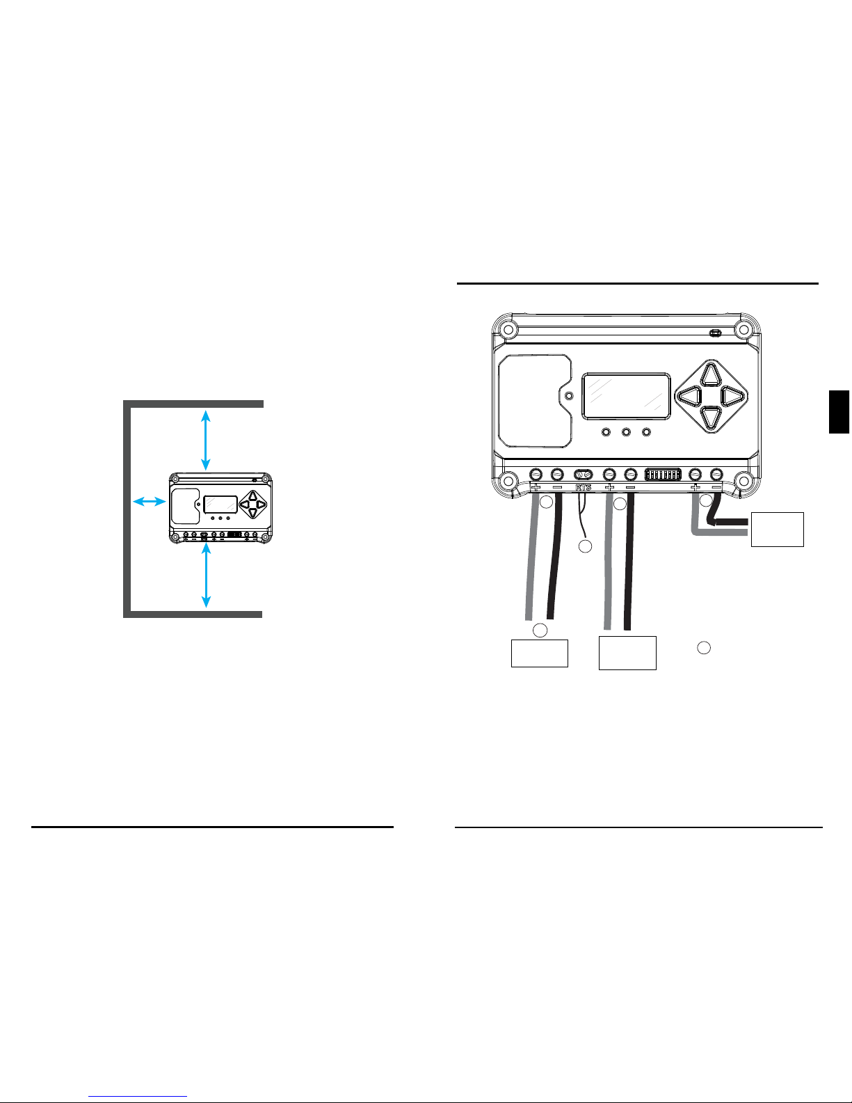
For proper air flow, allow at least 15 cm (6 in) of space
above and below the controller, and 50 mm (2 in) at
the sides - see Figure 3-1 below. Install in an area
protected from direct rain and direct sun.
If the controller is installed in an enclosure, some
ventilation is recommended. Do not locate in an
enclosure where battery gases can accumulate.
6 in / 150 mm
6 in / 150 mm
2 in /
50 mm
Figure 3-1. Proper Clearances for Passive Cooling
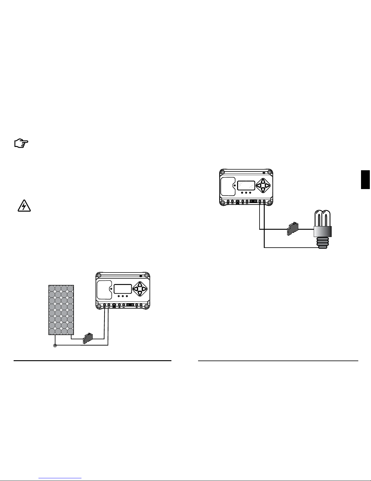
3.4 Wiring
To battery for
temperature
sensing
Not used in this illustration
To battery (+)
and (-)
terminals
To load (+)
and (-)
terminals
To properly
sized array
1
5
6
2
3
4
REFER TO FIGURE 3.2 WHEN USING THE FOLLOWING
WIRING INSTRUCTIONS
Figure 3-2. Wiring the EcoPulse
Installation
EcoPulse Operator’s Manual
15
14
3.0
STEP 1: Check Controller Limitations
Verify that the highest temperature compensated solar
array open-circuit voltage (Voc), and load current do
not exceed the ratings of the EcoPulse version being
installed.
STEP 2: Remote Temperature Sensor
WARNING: Risk of Fire.
If no Remote Temperature Sensor (RTS)
is connected, use the EcoPulse within 3m
(10ft) of the batteries. Internal Temperature
Compensation will be used if the RTS is
not connected. Use of the RTS is strongly
recommended.
Connect the RTS to the 2-position terminal located
(see figure). There is no polarity, so the (+) or (-) can
be connected to either screw terminal.
WARNING: Equipment Damage.
Never place the temperature sensor inside
abattery cell. Both the RTS and the battery
will be damaged.
CAUTION: The EcoPulse will use the local
temperature sensor for compensation if the RTS
is not used.
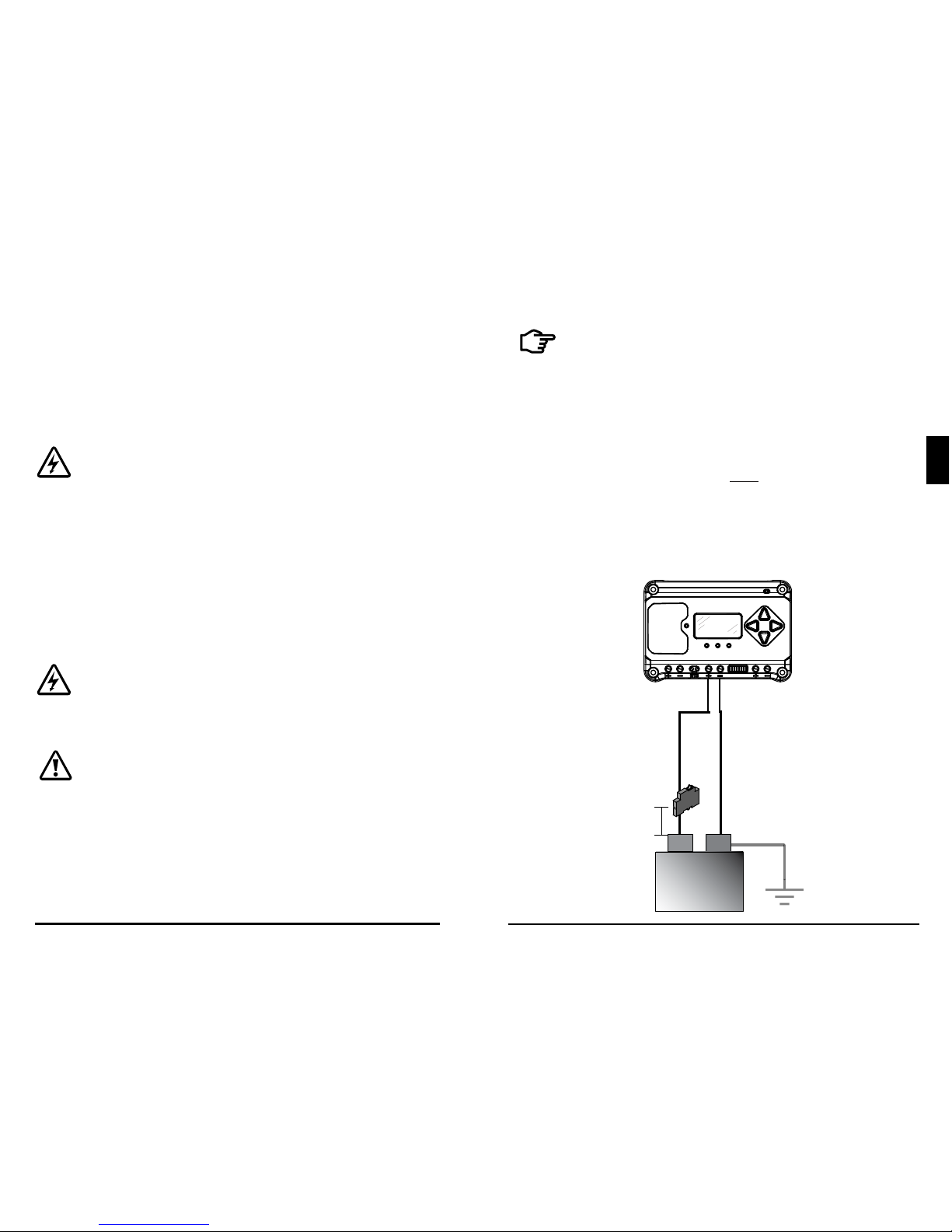
STEP 3:
Grounding
NOTE: Depending on the country of
installation, conductors identified by the
color green, or a combination of green /
yellow, shall only be used for earthing
conductors.
For safety, and effective lightning protection, it is
recommended, and may be locally required, that
the negative conductor of the charging system be
properly grounded. Use only one system earth
ground. For conductor sizing requirements, refer to
the U.S. National Electrical Code, or applicable local
regulations or code.
STEP 4: Battery Connections
(at battery
OR solar side,
but NOT both)
System Ground
6 in (150 mm)
Max.
Battery (-)
Battery (+)
+
-
12V or 24V
Battery
Fuse or breaker sizing
based on required wire
ampacity
Installation
EcoPulse Operator’s Manual
17
16
3.0
Be sure that DIP switches 2 and 3 are set for 12 or 24V,
as described in Section 3.2.
NOTE: Before connecting the battery, measure
the open-circuit voltage. It must be over 10Volts
to start the controller.
With the battery disconnect
open, connect the battery (+) and (-) wires from
the battery to controller. DO NOT CLOSE THE
DISCONNECT AT THIS TIME.
STEP 5: Solar Connections
WARNING: Shock Hazard.
The solar PV array can produce open-
circuit voltages of up to 60 Vdc when
in sunlight, and this DC voltage is
supplied to the Power Conversion
Equipment (PCE). Verify that the
solar input breaker or disconnect has
been opened (disconnected) before
installing the system wires.
SOLAR (+)
SOLAR (-)
(+)
(
-)
NOTE: For design purposes, array
should be nominal 12V for 12V
battery, and nominal 24V for 24V
battery. Do not exceed 60Voc
Solar
Disconnect
Fuse or breaker sizing
based on required wire
ampacity
With the solar disconnect open, connect the solar
(PV) array wires to the EcoPulse solar terminals.
Use caution, since the solar array will produce
current whenever in sunlight.
DO NOT CLOSE THE
DISCONNECT AT THIS TIME.
STEP 6: Load Connections
LOAD (+)
LOAD (-)
Fuse or breaker sizing
based on required wire
ampacity
Turn the loads off, and connect the load wires to the
load terminals. DO NOT CLOSE THE FUSE OR
BREAKER AT THIS TIME.
STEP 7: Power-Up and Verify System Operation
Close the battery disconnect to start the processor,
and activate the controller’s protections. Watch the
charging status, and then the three battery stateof-charge (SOC) LEDs blink in sequence (G-Y-R),
confirming proper start-up. If they do not light, check
the battery polarity (+/–) and battery voltage.
Installation
EcoPulse Operator’s Manual
19
18
3.0
The green, yellow or red LED will light depending on
the battery state-of-charge (SOC). Confirm that one of
these LEDs is on before going to the next step.
Close the solar disconnect. If the solar input is
connected while in sunlight, the charging LED
indicator will light. Confirm proper connection by
observing the charging LED.
Insert the load fuse, or close the breaker, and turn the
load on to confirm a proper connection.
STEP 8: To Power-Down
WARNING: Risk of Damage.
ONLY disconnect the battery from the EcoPulse
AFTER the solar input has been disconnected.
Damage to the controller may result if the battery
is removed while the EcoPulse is charging.
• To prevent damage, power-down must be done in
the reverse order as power-up.
3.5 Custom Settings
3.5.1 Adjusting the Meter Display
The display setting options are adjustable by using
the directional keys to locate and edit a desired
display setting.
3.5.2 Directional Key Use and Operation / Navigating
the Meter Map
A lit key indicates a valid direction in the meter
map. The current location is indicated on the
display with a column heading, and a bold descriptor.
3.5.3 Using the Meter Display to Program Charging
Set-points and Load Control
From the top level monitoring screens, scroll down
to the Main Menu - “Custom Programming” - screen.
Select the desired category, and edit the variable or
setting as instructed in the meter display.
Operation
EcoPulse Operator’s Manual
21
20
4.0
4.0 OPERATION
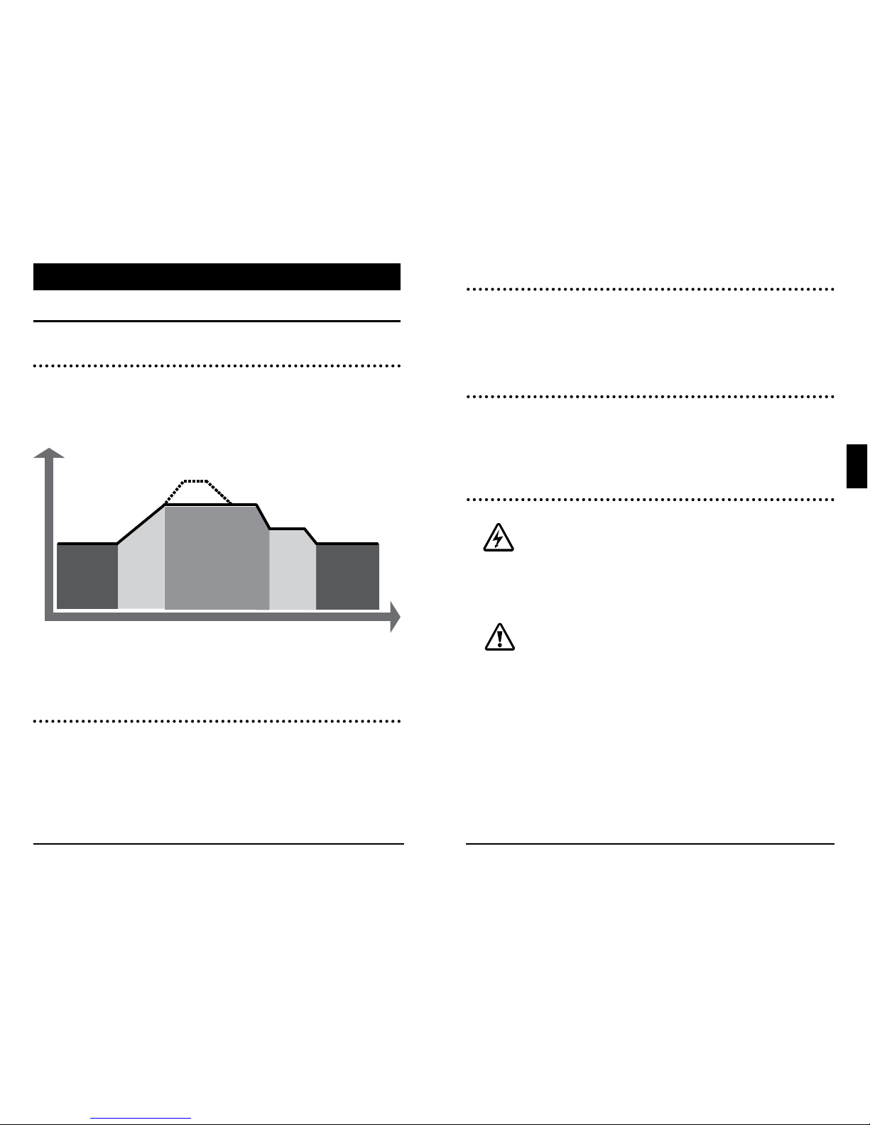
4.1 Battery Charging Information
4-Stage Charging
The EcoPulse has a 4-stage battery charging algorithm
for rapid, efficient, and safe battery charging. Figure
4-1 below, shows the sequence of stages.
Figure 4.1. EcoPulse Charging Algorithm
Bulk Charge Stage
During Bulk charging, the battery is not at 100% state
of charge and battery voltage has not yet charged to
the Absorption voltage set-point. The controller will
deliver 100% of available solar power to recharge the
battery.
NIGHT
NIGHT
BULK
CHARGE
ABSORPTION
FLOAT
EQUALIZE
VOLTAGE
TIME
Absorption Stage
When the battery has recharged to the Absorption
voltage set-point, constant voltage regulation is
used to maintain battery voltage at the Absorption
set-point.
Float Stage
After the battery is fully charged in the Absorption
stage, the EcoPulse reduces the battery voltage to
the Float voltage set-point. The purpose of float is to
protect the battery from long-term overcharge.
Equalization Stage
WARNING: Risk of Explosion.
Equalizing vented batteries produces
explosive gases. The battery bank must be
properly ventilated.
CAUTION: Equipment Damage.
Equalization increases the battery voltage
to levels that may damage sensitive DC
loads. Verify all system loads are rated for
the temperature compensated Equalize
voltage before beginning an Equalization
charge.
Operation
EcoPulse Operator’s Manual
23
22
4.0
CAUTION: Equipment Damage.
Excessive over-charging and gasing too
vigorously can damage the battery plates
and cause shedding of active material from
the plates. An equalization that is
too high, or too long, can be damaging.
Review the requirements for the particular
battery being used in your system.
Equalization (EQ) charging raises the battery voltage
above the standard absorption voltage so that the
electrolyte gases.
4.2 Load Information
CAUTION: Do not wire an AC inverter of any
size to the load terminals of the EcoPulse
- damage to the load control circuit may result.
Wire inverters directly to the battery or battery
bank.
4.3 LED Indications
KEY:
G = green G - Y - R = flashing sequentially
Y = yellow G / Y = flashing together
R = red G / Y - R = G and Y flashing together,
alternating with R flash
4.3.1 Power-up
Normal power-up: Status LED flashes G, then SOC
LEDS flash G - Y - R, then SOC LEDs indicate battery
charge status with a single battery status LED.
Failed bootload: Status LED flashes G, then SOC LEDS
flash G - Y and stop on solid Y.
4.3.2 Status LED
Table 4.1 below lists the Status LED indications.
Color Indication Operating State
None Off (with heartbeat) Night
Green
On Solid
( with heartbeat)
Charging
Red Flashing Error
Red
On Solid
( with heartbeat )
Critical Error
Table 4.1. Status LED Definitions
4.3.3 State-of-Charge LEDs
Battery SOC LED Indications are shown in Table 4.2
below:
Condition Indication
Absorption G flash - every sec
Float
G flash - every 2 secs
Equalize
G flash - 2 / sec
Low voltage disconnect warning
R flash - every sec
Low voltage disconnect
R solid
Table 4.2. Battery SOC LED Indications

Operation
EcoPulse Operator’s Manual
25
24
4.0
4.4 Protections, Faults and Alarms
4.4.1 Protections
Solar, battery and load transient surges
Power-up against any active faults
Reverse Polarity - battery and array
Solar Short-Circuit
Solar High Voltage Disconnect
High Heatsink Temperature - Load disconnect
Load Short-Circuit
Load Over-Current
Heatsink Temperature Limit
RTS Terminals
Battery Sense Terminals
4.4.2 LED Fault Indications
Solar Over-current
Error status LED: Flashing red. Battery status LEDs:
R/Y-G sequencing
Load Over-current
Error Status LED: Flashing red. Battery status LEDs:
R/Y-G sequencing
Solar Short Circuit
Charging Status LED: OFF
Battery Reverse Polarity
No LED indication, the unit is not powered
Load Short Circuit
Error status LED: Flashing red. Battery status LEDs:
R/G-Y sequencing
Solar High Voltage Disconnect
Charging Status LED: R flashing
Remote Temperature Sensor (RTS)
Error status LED: Flashing red. Battery status LEDs:
R/Y - G/Y sequencing
Battery / Load High Voltage disconnect (HVD)
Error status LED: Flashing red. Battery status LEDs:
R-G sequencing
High Heatsink Temperature
Error status LED: Flashing red. Battery status LEDs:
R-Y sequencing
Settings (DIP) Switch Changed
Error status LED: Flashing red. Battery status LEDs:
R-Y-G sequencing
Custom Settings Edit
Error status LED: Flashing red. Battery status LEDs:
R-Y-G sequencing
Internal Power Supply Out of Range
Error status LED: Solid red. Battery status LEDs:
R-Y-G sequencing. Contact your Morningstar dealer
for service
4.4.3 Alarms
High Temperature Current Limit
RTS Open
Heatsink Temperature Sensor Open or Shorted
Battery Sense Out of Range, or Disconnected
Uncalibrated
Operation
EcoPulse Operator’s Manual
27
26
4.0
4.5 Inspection and Maintenance
Table 4.3 below lists the recommended maintenance
schedule to keep your EcoPulse performing optimally.
Schedule Maintenance Items
2 weeks after installation
Re-tighten power terminal
connections to specified
torque values.
3 months after installation
Re-tighten power terminal
connections to specified
torque values.
Monthly, or After Each
Equalization
Inspect the battery bank.
Look for cracked or bulging
cases, and corroded
terminals.
For wet cell -flooded type
batteries, make sure the
water level is correct. Wet
cell water levels should be
check monthly according to
the manufacturer’s
recommendations.
Table 4.3. Maintenance Schedule (Cont.)
Schedule Maintenance Items
Monthly, or After Each
Equalization
Inspect the battery bank.
Look for cracked or bulging
cases, and corroded
terminals.
For wet cell (flooded
type) batteries, make
sure the water level is
correct. Wet cell water
levels should be checked
monthly or according to the
manufacturer’s
recommendations.
Annually
Clean the heatsink fins with
aclean, dry rag.
Inspect all wiring for
damage or fraying.
Inspect for nesting insects.
Re-tighten all wiring
terminal connections to
specified torque values.
Inspect the system
earth grounding for all
components. Verify all
grounding conductors are
appropriately secured to
earth ground.
Table 4.3. Maintenance Schedule (End)

EcoPulse Operator’s Manual
29
6.0
Warranty and Policies28
LIMITED WARRANTY Morningstar Solar Controllers and Inverters
The EcoPulse is warrantied to be free from defects in material and workmanship
for a period of TWO (2) years from the date of shipment to the original end user.
Morningstar will, at its option, repair or replace any such defective units.
WARRANTY EXCLUSIONS AND LIMITATIONS:
This warranty does not apply under the following conditions:
♦ Damage by accident, negligence, abuse or improper use
♦ PV or load currents exceeding the ratings of the product
♦ Unauthorized product modification or attempted repair
♦ Damage occurring during shipment
♦ Damage results from acts of nature such as lightning and weather extremes
THE WARRANTY AND REMEDIES SET FORTH ABOVE ARE EXCLUSIVE AND IN
LIEU OF ALL OTHERS, EXPRESS OR IMPLIED. MORNINGSTAR SPECIFICALLY
DISCLAIMS ANY AND ALL IMPLIED WARRANTIES, INCLUDING, WITHOUT
LIMITATION, WARRANTIES OF MERCHANTABILITY AND FITNESS FOR A
PARTICULAR PURPOSE. NO MORNINGSTAR DISTRIBUTOR, AGENT OR
EMPLOYEE IS AUTHORIZED TO MAKE ANY MODIFICATION OR EXTENSION
TO THIS WARRANTY.
MORNINGSTAR IS NOT RESPONSIBLE FOR INCIDENTAL OR
CONSEQUENTIAL DAMAGES OF ANY KIND, INCLUDING BUT NOT LIMITED
TO LOST PROFITS, DOWN-TIME, GOODWILL OR DAMAGE TO EQUIPMENT
OR PROPERTY.
5.0 WARRANTY
R17-8/16
EC-10/M EC-20/M EC-30/M
Electrical:
Nominal battery voltage All: 12 or 24 Volts
Battery voltage range All: 10-35 Volts
Max. Battery Current 10A 20A 30A
Max. PV open-circuit voltage All: 60 Volts
Load Current Rating 10A 20A 30A
Self Consumption <15mA (non-meter) <20mA (meter)
Mechanical:
Dimensions: 6.01(W) x 4.14(L) x 2.17(D) in.
153(W) x105(L) x 55(D) mm
Weight (lb/kg): Non-metered: 0.75 / 0.34 1.1 / 0.48
Metered: 0.90 / 0.40 1.2 / 0.54
Wire Size Range:
Power Terminals 2.5 - 16 mm2 / #14 - 6 AWG
Maximum Torque 35 in-lb
Battery/Temp. Sense 0.25 - 1.0 mm
2
/ #24 - 16 AWG
Enclosure IP20, Type 1
Battery Charging:
4-Stage Charging: Bulk, Absorption, Float, Equalize
Temperature compensation
Coefficient: -30mV / ºC / 12 Volt
Temperature compensated
set-points: Absorption, Float, Equalize, HVD
Environmental:
Maximum Operating Altitude 2000 meters
Operating Temperature -40ºC to +45ºC
Storage Temperature -40ºC to +80ºC
Humidity 100% n.c.
Tropicalization Conformally coated PCBs;
Marine-rated terminals
6.0 TECHNICAL SPECIFICATIONS
Certifications
30
• EN 61000-6-2: 2005/AC:2005 EMC Immunity
• EN 61000-6-4: 2007 +A1:2011 EMC Emissions
• Industry Canada: CAN ICES-3 (B)/NMB-3(B)
• IEC 62109-1: 2010 Safety of Power Converters in
PV Systems (TUV Pending)*
• JAS-ANZ Certification (TUV-Australia Pending)*
• Restriction of Hazardous Substances Directive
2011/65/EU (RoHS 2)
• Electromagnetic Compatibility Directive
2004/108/EC
• FCC (Title 47 of CFR), Part 15 Subpart B Class B
digital device
EcoPulseTM and MeterBus
TM
are trademarks of
Morningstar Corporation
MODBUSTM and MODBUS TCP/IPTM are trademarks of
Modbus IDA. www.modbus-ida.org
© 2017 Morningstar Corporation. All rights reserved.
* For current certifications, please go to:
support.morningstarcorp.com, and use the, “What Are You Looking
For?” menu to choose, "Corporate Documents". Then look for the
product Certificate of Conformity.
MS-001990 v2.3
TUVRheinland
®
CERTIFIED
APPENDIX - CERTIFICATIONS
REACH
ALL
COMPONENTS
COMPLIANT
Registration, Evaluation and
Authorization of Chemicals
www.morningstarcorp.com
EcoPulse
TM
Le présent document est un manuel abrégé. Pour consulter
lemanuel intégral du produit, veuillez vous référer à la version
papier en anglais ou à la version électronique sur:
www.morningstarcorp.com
Dieses Handbuch wurde gekürzt. Das vollständige
Produkthandbuch finden Sie in der gedruckten englischen
Version des Handbuchs oder in elektronischer Version unter:
www.morningstarcorp.com
Este es un manual resumido. Para consultar el manual completo
del producto, consulte la versión impresa en inglés del manual
ola versión que se encuentra en: www.morningstarcorp.com
Régulateur de charge solaire
Solarladesystem-Regler
Controlador del sistema de carga solar
Manuel de l’utilisateur...32
Bedienerhandbuch.........63
Manual del operador......94
EC-10 EC-10M
EC-20 EC-20M
EC-30 EC-30M
33
Manuel de l’utilisateur de l’EcoPulse
1.0
32
6.30
160
4.33
110
5.51
140
3.54
90
2.04
52
DIMENSIONS [pouces (millimètres)]
SYNTHÈSE DES SPÉCIFICATIONS
10/M 20/M 30/M
Tension nominale de la batterie 12/24V 12/24V 12/24V
Tension maximale en circuit
ouvert du système PV*
60V 60V 60V
Courant maximal de charge
de la batterie
10A 20A 30A
Courant de charge nominal 10A 20A 30A
* La tension du générateur ne doit jamais excéder cette limite.
CONSERVEZ CES INSTRUCTIONS.
Le présent manuel contient des consignes de sécurité ainsi
que des instructions d’installation, d’utilisation et d’entretien
importantes concernant le régulateur de charge solaire
EcoPulse.
Les symboles suivants sont utilisés tout au long du présent
manuel pour signaler les situations potentiellement
dangereuses ou souligner les consignes de sécurité
importantes:
ATTENTION: signale une situation potentiellement
dangereuse. Faites preuve d’une extrême prudence
pour effectuer cette tâche.
MISE EN GARDE: signale une procédure essentielle
pour l’utilisation sûre et adéquate du régulateur.
REMARQUE: signale une procédure ou une fonction
importante pour l’utilisation sûre et adéquate du
régulateur.
Informations relatives à la sécurité
• Veuillez lire l’intégralité des instructions et des mises
en garde contenues dans le présent manuel avant de
procéder à l’installation.
• L’EcoPulse ne contient aucune pièce susceptible d’être
réparée par l’utilisateur. N’essayez pas de le démonter
oude le réparer.
1.0 CONSIGNES DE SÉCURITÉ IMPORTANTES
FRANÇAIS
35
34
Manuel de l’utilisateur de l’EcoPulse
Consignes de sécurité importantes
1.0
• Utilisez des conducteurs et des interrupteurs de circuit
adaptés.
• Ce régulateur de charge doit être raccordé exclusivement
à des circuits DC. Ces raccordements DC sont identifiés
àl’aide du symbole suivant:
Symbole du courant continu
Le régulateur EcoPulse doit être installé par un technicien
qualifié conformément à la réglementation relative aux
équipements électriques en vigueur dans le pays d’installation.
Un dispositif de sectionnement doit être mis en place pour
l’ensemble des pôles d’alimentation. Ce dispositif doit être
incorporé au câblage fixe.
Les bornes d’alimentation négatives de l’EcoPulse sont
ordinaires et doivent être mises à la terre conformément aux
instructions, aux codes locaux et à la réglementation.
Consignes de sécurité relatives à la batterie
ATTENTION : les batteries peuvent présenter un
risque d’électrocution ou de brûlure en raison des
quantités importantes de courant de court-circuit ainsi
qu’un risque d’incendie ou d’explosion lié aux gaz
libérés. Veuillez prendre les précautions requises.
ATTENTION: risque d’explosion.
Veillez à mettre au rebut les batteries de manière
appropriée. Ne jetez pas les batteries au feu. Veuillez
vous référer à la réglementation ou aux codes locaux
pour connaître les exigences en matière de mise
aurebut.
ATTENTION: risque d’électrocution.
AUCUNE BORNE ACCESSOIRE OU D’ALIMENTATION
N’EST ISOLÉE ÉLECTRIQUEMENT DE L’ENTRÉE DC.
ELLES PEUVENT DONC ÊTRE SOUMISES À UNE
TENSION SOLAIRE DANGEREUSE. DANS CERTAINS
CAS DE DÉFAILLANCE, LA BATTERIE POURRAIT SUBIR
UNE SURCHARGE. EFFECTUEZ UN TEST ENTRE
TOUTES LES BORNES ET LA MISE À LA TERRE AVANT
TOUTE MANIPULATION.
• L’utilisation d’un sectionneur solaire et d’un sectionneur
de batterie externes est requise.
• Débranchez toutes les sources d’alimentation du
régulateur avant d’installer ou de régler l’EcoPulse.
• L’EcoPulse ne contient pas de fusibles ni de sectionneurs.
N’essayez pas de le réparer.
Consignes de sécurité lors de l’installation
• Montez l’EcoPulse à l’intérieur. Installez-le à l’abri des
éléments et des infiltrations d’eau.
• Installez l’EcoPulse à l’abri de tout contact accidentel.
Le dissipateur thermique de l’EcoPulse peut devenir très
chaud lors du fonctionnement.
• Utilisez des outils isolés pour travailler sur les batteries.
• Évitez de porter des bijoux lors de l’installation.
• Le banc de batteries doit être composé de batteries du
même type, de la même marque et du même âge.
• Certifié UL/CEI62109 pour utilisation avec mise à la terre
négative et systèmes flottants uniquement.
• Ne pas fumer à proximité du banc de batteries.
• Les branchements électriques doivent demeurer
serrés afin d’éviter toute chaleur excessive due à un
branchement lâche.
FRANÇAIS
 Loading...