

Morningstar EB-MPPT-20, EB-MPPT-30, EB-MPPT-40M, EB-MPPT-30M, EB-MPPT-20M Installation, Operation And Maintenance Manual
...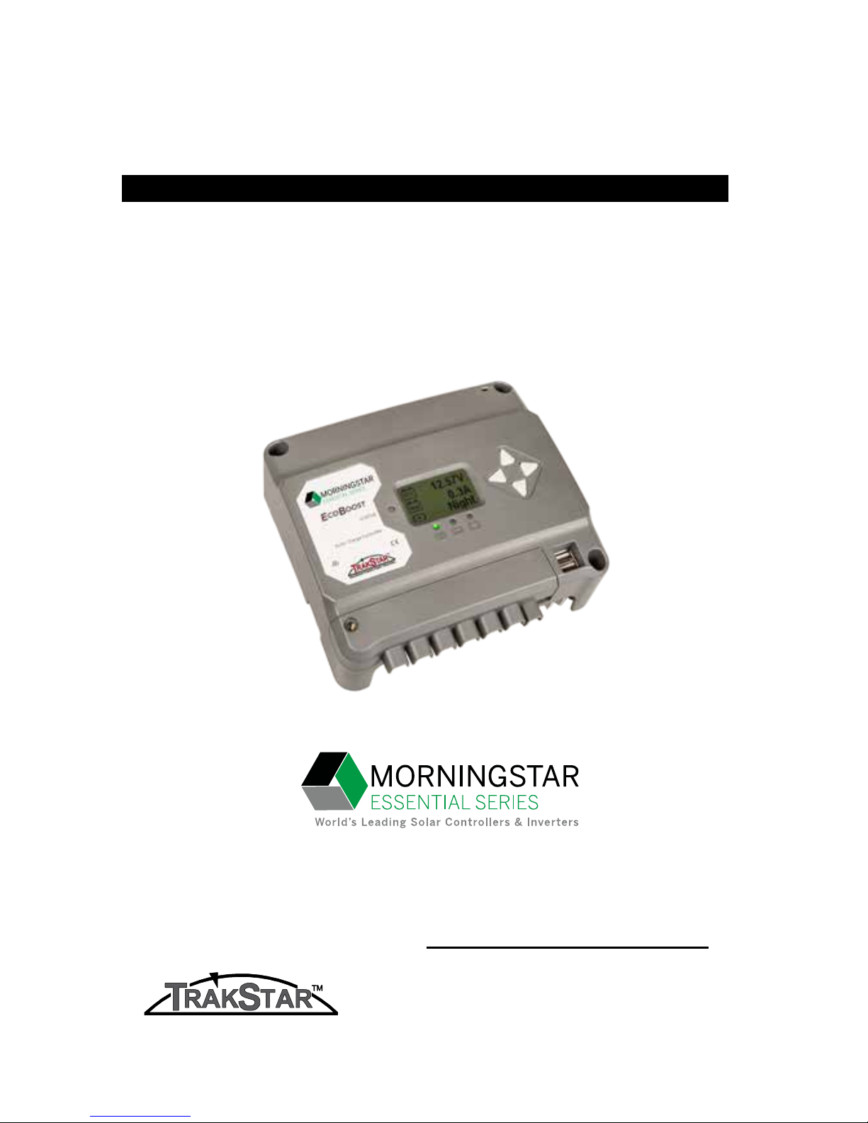
Solar Charging System Controller
Installation, Operation and Maintenance Manual
www.morningstarcorp.com
EcoBoost MPPT
TM
MAXIMUM POWER POINT TRACKING
For the most recent manual revisions, see the version at:
www.morningstarcorp.com
MODELS
EB-MPPT-20 EB-MPPT-20M
EB-MPPT-30 EB-MPPT-30M
EB-MPPT-40 EB-MPPT-40M
EcoBoost MPPT Operator’s Manual
iii
ii
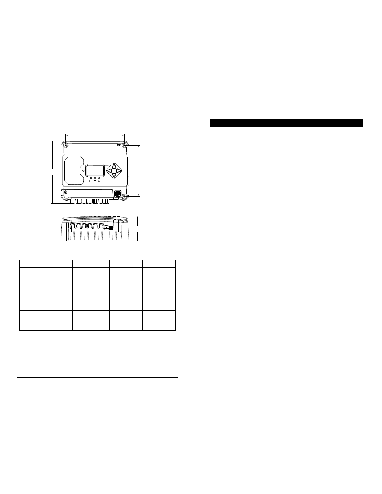
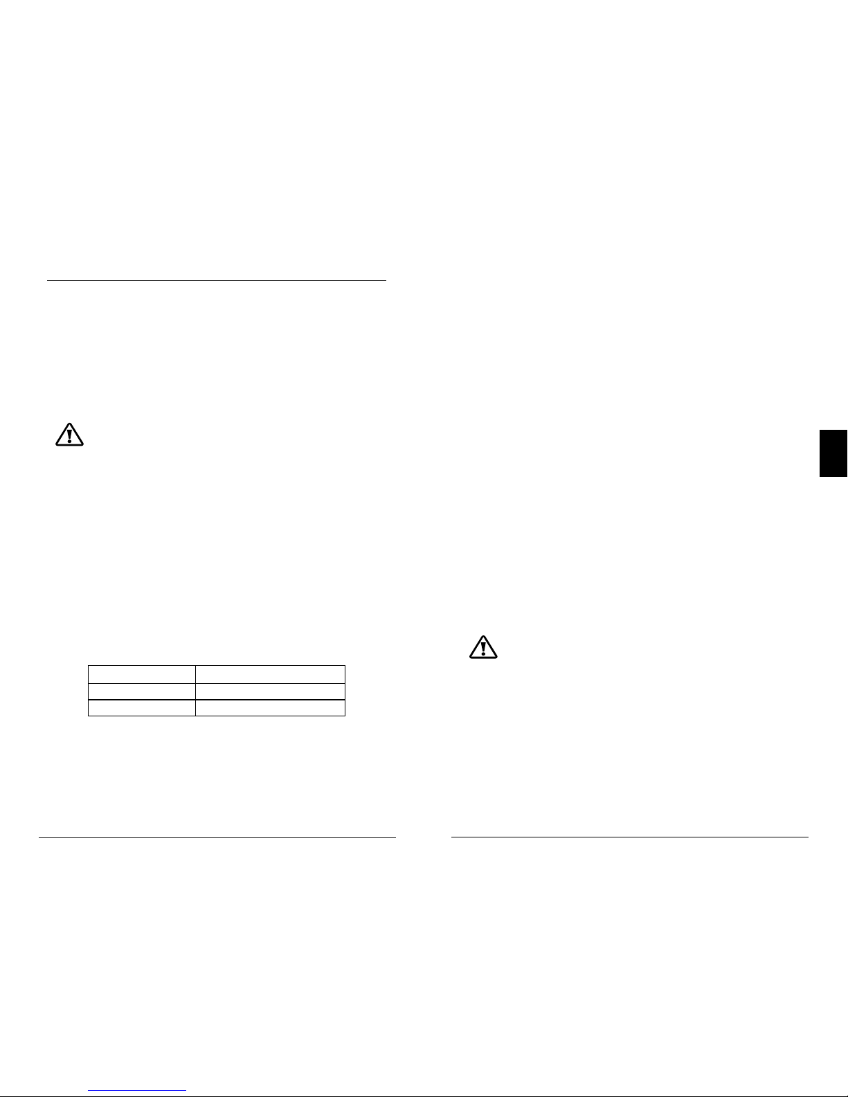
SPECIFICATION SUMMARY
EB-MPPT-20 EB-MPPT-30 EB-MPPT-40
Nominal Battery
Voltage
12/24V 12/24V 12/24V
Max. PV Open-
Circuit Voltage*
120V 120V 120V
Nominal Max.
InputPower**
300 / 600W 400 / 800W
560 /
1120W
Max. Battery
Charging Current
20A 30A 40A
Rated Load Current 20A 30A 30A
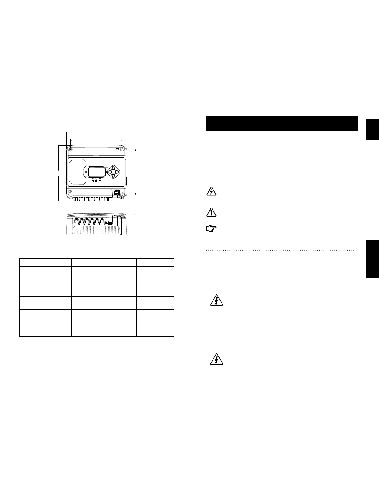
DIMENSIONS (centimeters)
TABLE OF CONTENTS
1.0 Important Safety Instructions ........................... 1
2.0 General Information
.... .................................... ... 5
2.1 Overview
................................................................5
2.2
Features
................................................................. 6
2.3 Optional Accessories
..............................................8
3.0 Installation ..............................................................9
3.1 General Installation Notes
.......................................9
3.2 Configuration
........................................................11
3.3 Mounting
..............................................................14
3.4 Wiring
..................................................................15
4.0 Operation ............................................................ 23
4.1 TrakStar MPPT Technology ...................................... 23
4.2 Battery Charging Information ..................................23
4.3 Load Control Information ....................................... 26
4.4 LED Indications......................................... .... .........28
4.4.1 Power-up..................................................................28
4.4.2 Status LED.............................................................. 28
4.4.3 State-of-charge LEDs...............................................29
4.5 Alarms......................................................................29
4.6 Custom Settings.......................................................31
4.6.1 Adjusting Set-points with Meter Display................ 31
4.6.2 Meter Display Operation......................................... 32
4.6.2.1 Directional Key Use and Operation / Navigating
the Meter Map........................................................32
4.6.2.2 Adjusting the Meter Display................................. .32
4.7 Data Logging (future use).......................................32
4.8 Auxilliary USB Charging..........................................33
4.9 Inspection and Maintenance.................................. .33
Continued...
*Array voltage should never exceed this limit
**These power levels refer to the maximum wattage the EcoBoost MPPT
can process. Higher power arrays can be used without damaging the
controller.
(
14.8 )
( 17.0 )
( 19.6 )
(
18.1
)
(
7.1
)

1.0
EcoBoost MPPT Operator’s Manual
1
iv
1.0 IMPORTANT SAFETY INSTRUCTIONS
SAVE THESE INSTRUCTIONS.
This manual contains important safety, installation, operating
and maintenance instructions for the EcoBoost MPPT solar
controller.
The following symbols are used throughout this manual to
indicate potentially dangerous conditions or mark important
safety instructions:
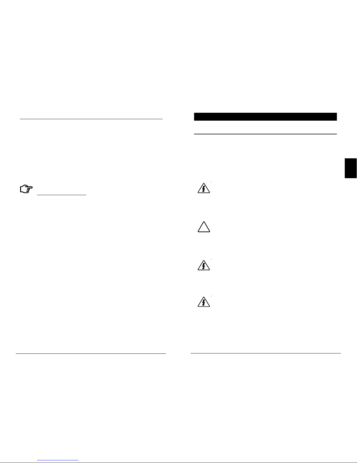
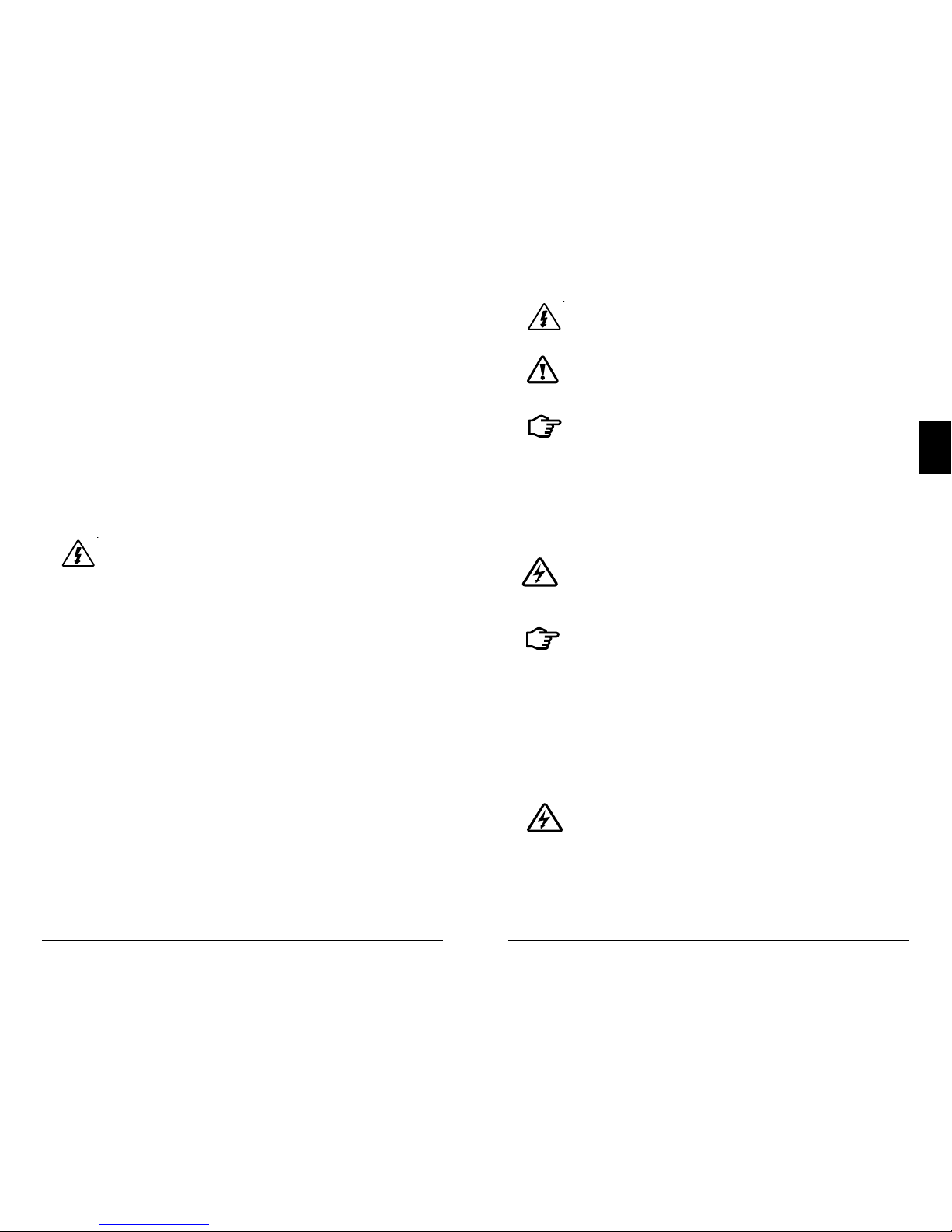
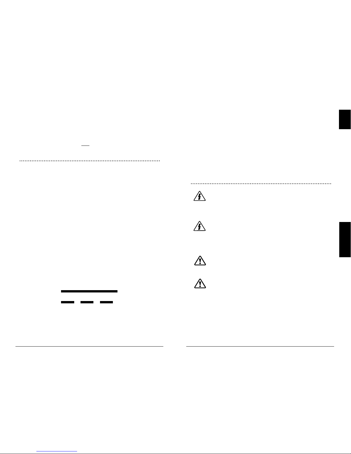
WARNING: Indicates a potentially dangerous condition.
Use extreme caution when performing this task.
CAUTION: Indicates a critical procedure for safe and
proper operation of the controller.
NOTE: Indicates a procedure or function that is important
to the safe and proper operation of the controller.
Safety Information
• Read all of the instructions and cautions in the manual
before beginning installation.
• There are no user serviceable parts inside the
EcoBoost MPPT. Do not disassemble or attempt to repair
the controller.
WARNING: Risk Of Electrical Shock.
NO POWER OR ACCESSORY TERMINALS ARE
ELECTRICALLY ISOLATED FROM DC INPUT, AND MAY BE
ENERGIZED WITH HAZARDOUS SOLAR VOLTAGE. UNDER
CERTAIN FAULT CONDITIONS, BATTERY COULD BECOME
OVER-CHARGED. TEST BETWEEN ALL TERMINALS AND
GROUND BEFORE TOUCHING.
WARNING: THE COMMUNICATIONS PORT IS
CONSIDERED TO BE DVC B. AN EXTERNAL
ISOLATOR IS REQUIRED IF IT IS TO BE CONNECTED TO A DVC
A CIRCUIT.
.....Continued
5.0 Troubleshooting...........................................35
5.1 LED Fault Indications...................................................35
5.2 Battery Charging and Performance Issues.................39
6.0 Warranty ....................................................40
7.0 Technical Specifications...............................41
8.0
Certifications...............................................44
1.0
Important Safety Instructions
EcoBoost MPPT Operator’s Manual
32
A means of disconnecting all power supply poles must be
provided. These disconnects must be incorporated in the
fixed wiring.
The EcoBoost MPPT negative power terminals are common,
and must be grounded as instructions, local codes, and
regulations require.
A permanent, reliable earth ground must be established
with connection to the EcoBoost MPPT heatsink.
The grounding conductor must be secured against any
accidental detachment.
Battery Safety
WARNING: A battery can present a risk of electrical
shock or burn from large amounts of short-circuit
current, fire, or explosion from vented gases.
Observe proper precautions.
WARNING: Risk of Explosion.
Proper disposal of batteries is required. Do not
dispose of batteries in fire. Refer to local
regulations or codes for requirements.
CAUTION: When replacing batteries, use properly
specified number, sizes, types, and ratings based on
application and system design.
CAUTION: Do not open or mutilate batteries.
Released electrolyte is harmful to skin, and may be
toxic.
• Servicing of batteries should be performed, or supervised,
by personnel knowledgeable about batteries, and the
proper safety precautions.
• Be very careful when working with large lead-acid
batteries. Wear eye protection and have fresh water
available in case there is contact with the battery acid.
• Remove watches, rings, jewelry and other metal objects
before working with batteries.
• Wear rubber gloves and boots
• External solar and battery disconnects are required.
• Disconnect all sources of power to the controller before
installing or adjusting the EcoBoost MPPT.
• There are no fuses or disconnects inside the
EcoBoost MPPT Do not attempt to repair.
Installation Safety Precautions
• Mount the EcoBoost MPPT indoors. Prevent exposure
to the elements and do not allow water to enter the
controller.
• Install the EcoBoost MPPT in a location that prevents
casual contact. The EcoBoost MPPT heatsink can become
very hot during operation.
• Use insulated tools when working with batteries.
• Avoid wearing jewelry during installation.
• The battery bank must be comprised of batteries of same
type, make, and age.
• IEC 62109 certified for use in negative ground or floating
systems only.
• Do not smoke near the battery bank.
• Power connections must remain tight to avoid excessive
heating from a loose connection.
• Use properly sized conductors and circuit interrupters.
• This charge controller is to be connected to DC circuits
only. These DC connections are identified by the symbol
below:
Direct Current Symbol
The EcoBoost MPPT controller must be installed by a
qualified technician in accordance with the electrical
regulations of the country of installation.

EcoBoost MPPT Operator’s Manual
5
2.0
Important Safety Instructions
4
• Use tools with insulated handles and avoid placing tools
or metal objects on top of batteries.
• Disconnect charging source prior to connecting or
disconnecting battery terminals.
• Determine if battery is inadvertently grounded. If so,
remove the source of contact with ground. Contact with
any part of a grounded battery can result in electrical
shock. The likelihood of such a shock can be reduced
if battery grounds are removed during installation and
maint enance (applicable to equipment and remote
battery supplies not having a grounded supply circuit).
• Carefully read the battery manufacturer's instructions
before installing / connecting to, or removing batteries
from, the EcoBoost MPPT.
• Be very careful not to short circuit the cables connected
to the battery.
• Have someone nearby to assist in case of an accident.
• Explosive battery gases can be present during charging.
Be
certain there is enough ventilation to release the
gases.
• Never smoke in the battery area.
• If battery acid comes into contact with the skin, wash
with
soap and water. If the acid contacts the eye, flood
with fresh water and get medical attention.
• Be sure the battery electrolyte level is correct before starting
charging. Do not attempt to charge a frozen battery.
• Recycle the battery when it is replaced.
2.1 Overview
Thank you for choosing the EcoBoost MPPT charge controller with TrakStarTM MPPT Technology. The EcoBoost MPPT
is an advanced maximum power point tracking solar battery
charger. The controller features a smart tracking algorithm
that finds and maintains operation at the power source's
peak power point, maximizing energy harvest.
The EcoBoost MPPT battery charging process has been
optimized for long battery life and improved system
performance. Self-diagnostics and electronic error
protections prevent damage when installation mistakes or
system faults occur. The controller also features eight (8)
adjustable settings switches, several communication ports,
and terminals for remote battery temperature and voltage
measurement.
Please take the time to read this operator’s manual to
become familiar the many benefits the EcoBoost MPPT can
provide for your PV systems, for example:
• Rated for 12 or 24 volt systems, and 20, 30 or 40 amps of
charging current
• Fully protected with automatic and manual recovery
• Seven standard charging programs selectable with DIP
switches
• Continuous self-testing with fault notification
• LED indications and push-button or meter key functions
• Power terminal maximum of #6 AWG wire.
• Digital meter display options
• Optional remote battery temperature sensor
• 2-year warranty (see Section 6.0)
2.0 GENERAL INFORMATION
General Information
EcoBoost MPPT Operator’s Manual
7
6
2.0
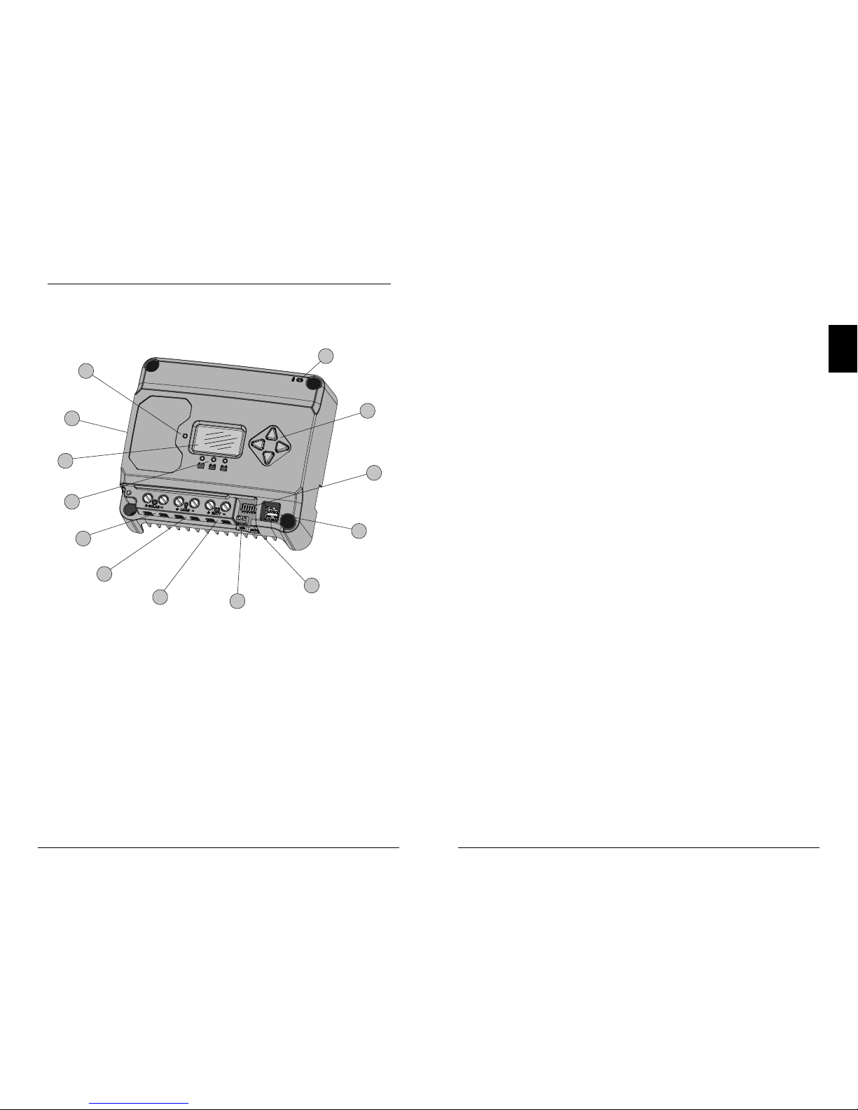
2.2 Features
The features of the EcoBoost MPPT are shown in Figure 2-1
below. An explanation of each feature is provided below.
1
5
8
6
13
9
7
4
2
3
11
10
12
Figure 2-1. EcoBoost MPPT Features
1 - Charging Status / Error LED
Indicates charging and error condition statuses.
2 - Heatsink / Grounding Screw (M4 screw for grounding heatsink)
Aluminum heatsink (underneath) to dissipate controller heat (the
EcoBoost MPPT is 100% passively cooled for reliability)
3 - Meter Display
Digital LCD monitoring and programming display
4 - Battery Status / Fault LED Indicators
Three state of charge (SOC) LED indicators show charging status and
controller faults
5 - Solar Positive and Negative Terminals
Power connections for Solar (+) and (-) cable terminations
6 - Load Positive and Negative Terminals
Power connections for Load (+) and (-) cable terminations
7 - Battery Positive and Negative Terminals
Power connections for Battery (+) and (-) cable terminations
8 - Remote Temperature Sensor Terminals (RTS)
Connection points for a Morningstar RTS to remotely monitor battery
temperature
9 - USB Micro-B Data Port (future use)
Micro-B USB port for (future) data transfer
10 - USB-A Charging Ports
USB-A sockets for charging electronic devices
11 - DIP Switches
Eight (8) settings switches to configure operation of the EcoBoost MPPT
12 - Meter Directional Buttons
Used to navigate throughout meter map
13 - Local Temperature Sensor
Compensates charging based on ambient temperature (not used if
Remote Temperature Sensor is connected)
EcoBoost MPPT Operator’s Manual
9
3.0
General Information
8
2.3 Optional Accessories
The following accessories are available for purchase
separately from your authorized Morningstar dealer:
Remote Temperature Sensor (Model: RTS)
The RTS measures battery temperature for accurate
temperature compensation and is recommended when
the ambient battery temperature differs from the ambient
controller temperature by more than 5º C. The standard
cable length is 33 ft (10m).
N
OTE: The use of a Remote Temperature Sensor is
strongly recommended. Controller location, air flow, and
system power can drastically affect the local temperature sensor
reading. An RTS will provide optimal charg
ing performance.
Ground-fault Protection Device (GFPD-150V)
As a safety measure, the GFPD-150V detects power source
ground faults and interrupts current.
3.1 General Installation Notes
• Read through the entire installation section first before
beginning installation.
• Be very careful when working with batteries. Wear
eye protection. Have fresh water available to wash
and clean any contact with battery acid.
• Use insulated tools and avoid placing metal objects
near the batteries.
WARNING: Equipment Damage or Risk of
Explosion
Never install the EcoBoost MPPT in an enclosure
with vented/flooded batteries. Battery fumes
are flammable and will corrode and destroy the
EcoBoost MPPT circuits.
CAUTION: Equipment Damage
When installing the EcoBoost MPPT in an
enclosure, ensure sufficient ventilation. Installation
in a sealed enclosure will lead to over-heating and
a decreased product lifetime.
WARNING: Equipment Damage
The EcoBoost MPPT is designed for negative
or floating ground systems ONLY, and is NOT
approved for use in a positive ground system.
Damage to USB connected devices may result.
WARNING: Equipment Damage
DO NOT connect a laptop PC to the USB data
port while the laptop is connected to an AC
charger. Damage to the USB port may result.
!
3.0 INSTALLATION
Installation
EcoBoost MPPT Operator’s Manual
1110
3.0
• Do not install in locations where water can enter the
controller.
• Loose power connections and /or corroded wires
may result in resistive connections that melt wire
insulation, burn surrounding materials, or even cause
fire. Ensure tight connections and use cable clamps to
secure cables and prevent them from swaying in mobile
applications.
• Preset charging profiles are generally designed for
lead acid batteries. Custom settings can be used for
varied charging requirements (see sections 3.2 and 4.7
for details). Note that some battery types may not be
compatible.
• The EcoBoost MPPT battery connection may be wired
to one battery, or a bank of batteries. The following
instructions refer to a singular battery, but it is implied
that the battery connection can be made to either one
battery or a group of batteries in a battery bank.
• The EcoBoost MPPT uses self-tapping fasteners,
an anodized aluminum heat sink, and conformal
coating to protect it from harsh conditions. However,
for acceptable service life, extreme temperatures and
marine environments should be avoided.
• The EcoBoost MPPT prevents reverse current leakage at
night, so a blocking diode is not required in the system.
• The EcoBoost MPPT is designed to regulate ONLY solar
(photovoltaic) power. Connection to any other type of
power source e.g. wind turbine or generator may void
the warranty. However, other power sources can be
connected directly to the battery.
• The maximum power terminal wire size is #6 AWG /
16 mm
2
(solid/multi-strand) or #8 AWG / 10 mm2 (fine
strand). Use a flathead insulated screwdriver, and
torque tightly up to 3.95 Nm.
• Stranded wires to be connected to the EcoBoost MPPT
terminals should be prepared first with e.g. clamped
copper heads, etc. to avoid the possibility of one
conductor free out of the connection screw, and
possible contact with the metal enclosure.
WARNING: Solar and battery fuses or DC breakers
are required in the system. These protection devices
are external to the EcoBoost MPPT controller, and must be a
maximum of 25 amps for the EB-20/M, 35 amps for the EB30/M, and 50 amps for the EB-40/M.
WARNING: Breakers and fuses may require lower
ratings than referenced above, so as not to exceed
any specific wire ampacity.
WARNING: Minimum over-current protection
device interrupt ratings must be 2000A for 12V
systems, and 4000A for 24V systems.
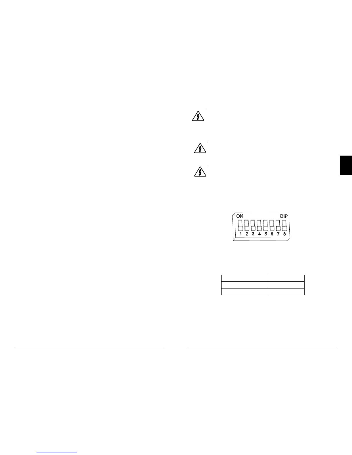
3.2 Configuration
The DIP switch block shown in Figure 3.1 below is used to
set the operating parameters for the EcoBoost MPPT.
Switch 1: Load / Lighting
Mode Switch 1
Normal OFF
Lighting ON
With DIP 1 ON, the EcoBoost MPPT will follow a dusk-todawn lighting schedule.
Figure 3.1. DIP Switch Block to set charging parameters
Installation
EcoBoost MPPT Operator’s Manual
1312
3.0
Switches 2, 3: System Voltage
Three (3) system voltage configurations are available as
shown in the table below:
System Voltage Switch 2 Switch 3
Auto OFF OFF
12 OFF ON
24 ON OFF
NOTE: Before connecting the battery, measure the open-circuit
voltage. It must be over 10 volts to start the controller. If the
system voltage Settings Switches are set to Auto-detect, battery
voltage over 15.5V will be detected as a 24V nominal battery,
and the unit will charge accordingly. The 12/24V auto selection is
only done at start-up, and the detected system voltage will never
change during operation.
Generally, the specfic system voltage is known, and it is best
to set DIPs 2,3 accordingly; the auto-detect setting should
be used only in rare circumstances.
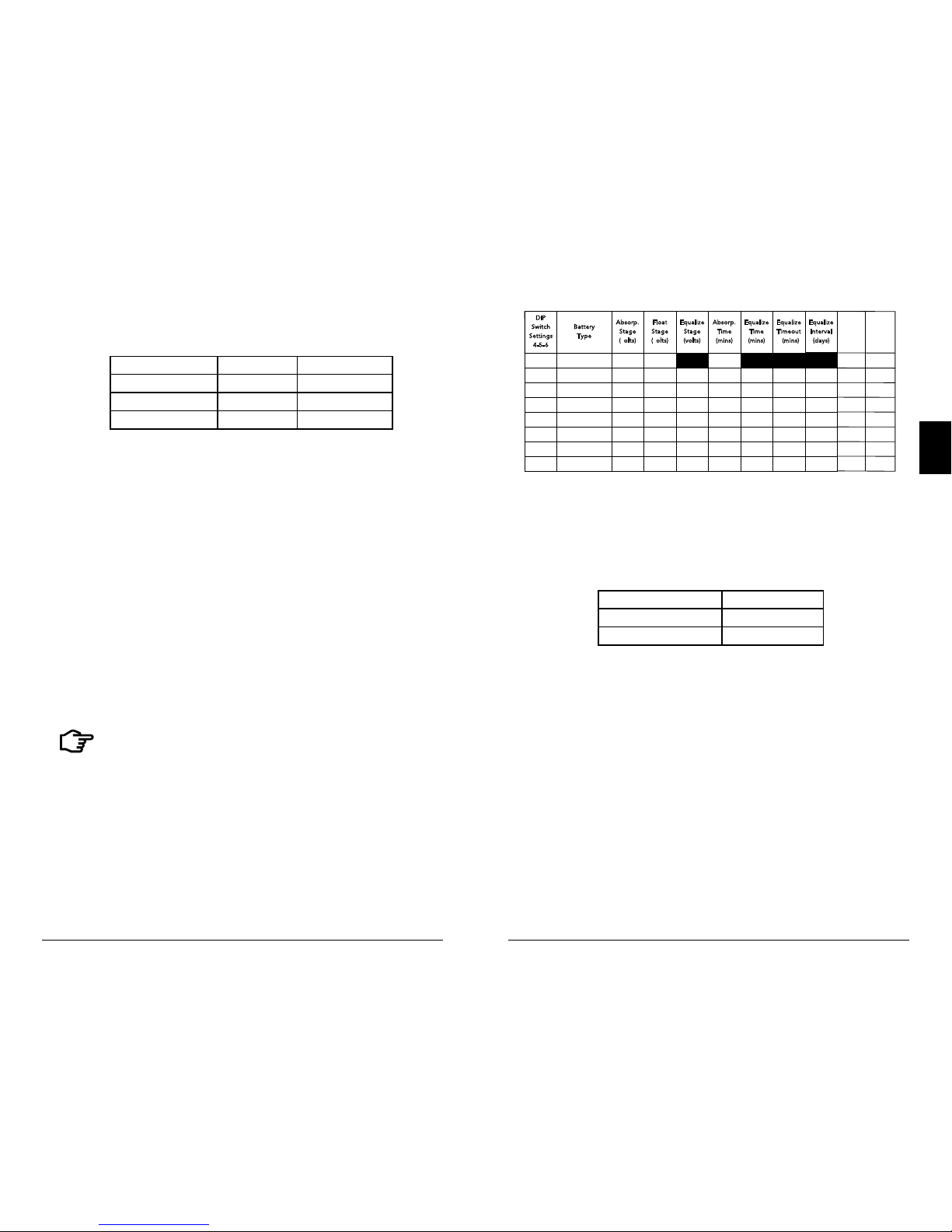
Switches 4, 5, 6: Battery Type Selection
Preset EcoBoost MPPT battery charging options are shown
in table 3-1 below. All voltage settings listed are for nominal
12 volt batteries.
Multiply the voltage settings by two (2) for 24 volt systems.
NOTE: These settings are general guidelines for
use at the operator’s discretion. The
EcoBoost MPPT can be programmed to satisfy a wide range
of charging parameters.
Consult the battery manufacturer for
optimal battery charge settings.
DIP
S
witch
S
etting s
4
-5-6
B
attery
T
ype
A
bsorp.
S
tage
(
volts)
F
loat
S
tage
(
volts)
E
qualiz e
S
tage
(
volts)
A
bsorp.
T
ime
(
mins)
E
qualiz e
T
ime
(
mins)
E
qualiz e
T
imeout
(
mins)
E
qualiz e
Equaliz e
Equaliz e
I
nterval
(
days)
Equaliz e
Interva l
(days)
Equaliz e
Interva l
(days)
off-off-off 1 - Sealed* 14.00 13.50
150
off-off-on 2 - Seal ed* 14.15 13.50 14.40 150 60 120 28
off-on-off 3 - Seal ed* 14.30 13.50 14.60 150 60 120 28
off-on-on 4- AGM/Flooded 14.40 13.50 15.10 180 120 180 28
on-off-off 5 - Flo oded 14.60 13.50 15.30 180 120 180 28
on-off-on 6 - Flooded 14.70 13.5 0 15.40 180 180 240 28
on-on-off 7 - L-16 15.40 13.40 16.00 180 180 240 14
on-on-on 8 - Custom Custom Custom Custom Custom Custom Custom Custom
Custom Cu stom
Custom
* “Sealed” baery type includes gel and AGM baeries
Custom
LVD
(volts)
LVR
(volts)
Custom
12.30
13.80
12.10 13.60
11.90
13.40
11.50
13.00
11.70
13.20
11.30
12.80
11.50
12.60
Table 3.1. Battery charging settings for each selectable battery type
Switch 7: Battery Equalization
Mode Switch 7
Manual Equalization OFF
Auto Equalization ON
Switch 8: Reserved for Future Use
Installation
EcoBoost MPPT Operator’s Manual
1514
3.0
3.3 Mounting
Inspect the controller for shipping damage. Mount the EcoBoost MPPT to a vertical surface (4-#8 self-tapping screws
are included). Tighten the mounting screws, using care not
to crack the plastic case. Do not install directly over an easily
combustible surface since the heat sink may get hot under
certain operating conditions.
NOTE: The heat sink must be in a vertical position (fins
up and down).
For proper air flow, allow at least 15 cm (6 in) of space
above and below the controller, and 50 mm (2 in) at the
sides - see Figure 3-2 below. Install in an area protected
from direct rain and sun.
If the controller is installed in an enclosure, some
ventilation is recommended. Do not locate in an enclosure
where battery gases can accumulate.
Figure 3-2. Proper Clearances for Passive Cooling
15 cm
15 cm
5 cm
+
-
2
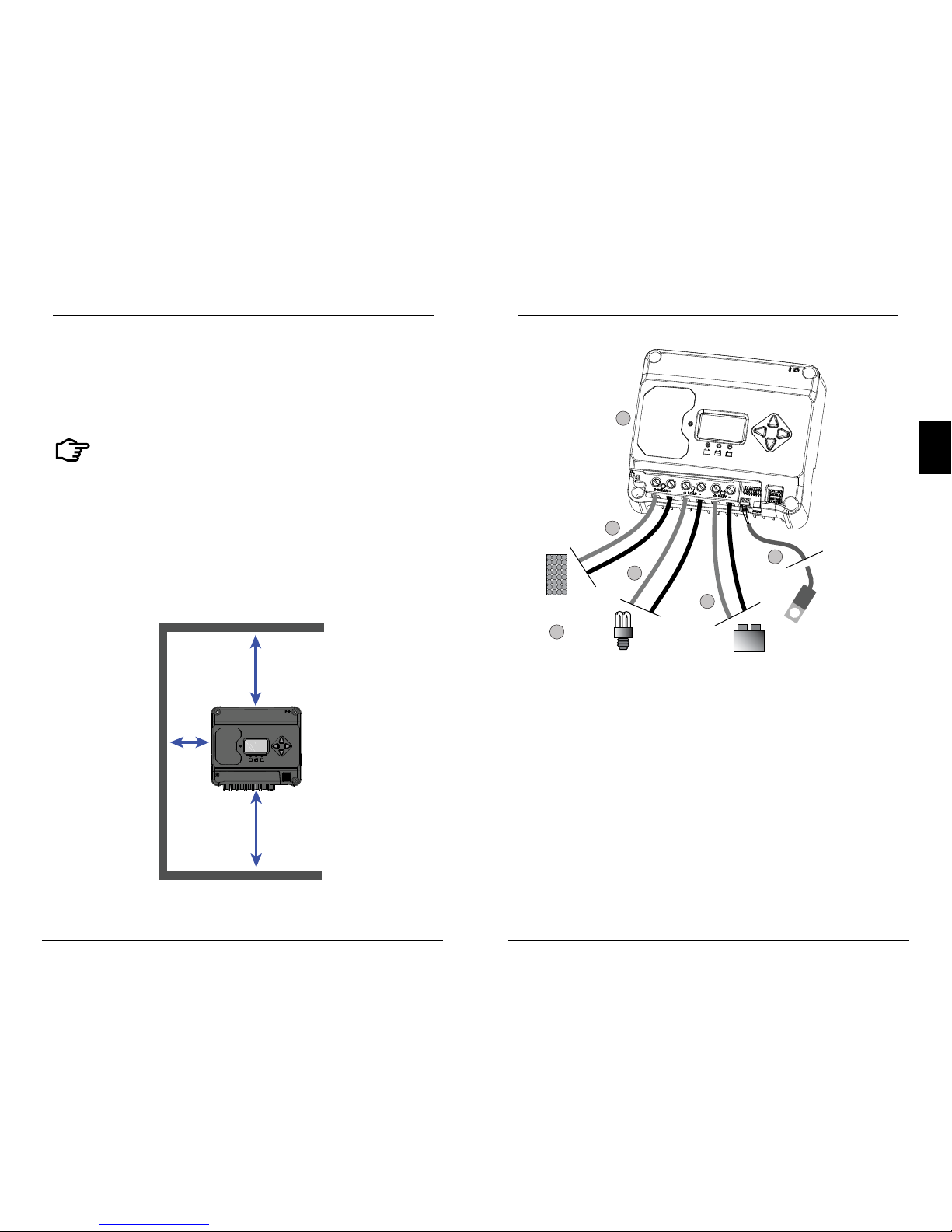
1
3
4
5
6
To properly
sized PV array
To battery (+)
and (-) terminals
To load (+) and
(-) terminals
To battery (-) post for
temperature sensing
+
+
+
-
-
-
3.4 Wiring
Figure 3-3. Wiring the EcoBoost MPPT
REFER TO FIGURE 3.3 WHEN USING THE WIRING INSTRUCTIONS
BELOW.
Installation
EcoBoost MPPT Operator’s Manual
1716
3.0
STEP 1: Check Controller Limitations
Verify that the highest temperature compensated solar array
open-circuit voltage (Voc), and load current do not exceed
the ratings of the EcoBoost MPPT version being installed.
Multiple controllers can be installed in parallel on the same
battery bank to achieve greater total charging current. In
this type of system, each EcoBoost MPPT must have its
own solar array. The load terminals of multiple controllers
can only be wired together if the total load draw does
not exceed the nameplate current of the LOWEST rated
controller.
STEP 2: Remote Temperature Sensor
WARNING: Risk of Fire.
If no Remote Temperature Sensor (RTS) is connected,
use the EcoBoost MPPT within 3m (10 ft) of the batteries. Internal
Temperature Compensation will be used if the RTS is not
connected. Use of the RTS is strongly recommended.
All charging settings are based on 25°C (77°F). If the
battery temperature varies by 5°C, the charging setting
will change by 0.15 Volts for a 12 Volt battery. This is a
substantial change in the charging of the battery, and the
use of the
optional Remote Temperature Sensor (RTS) is recommended
to adjust charging to the actual battery temperature. The
RTS can be added at any time after the system has been
installed.
Connect the (+) and (-) RTS wires to the 2-position terminal
located below the DIP switches (see figure 3.3).
The RTS is supplied with 10 m of 22 AWG (0.34 mm
2
) cable.
There is no polarity, so either wire (+ or -) can be connected
to either screw terminal. The RTS cable may be pulled
through conduit along with the power wires. Tighten the
connector screws to 0.56 Nm of torque. Separate installation instructions are provided inside the RTS bag.
WARNING: Equipment Damage
Never place the temperature sensor inside a battery cell.
Both the RTS and the battery will be damaged.
CAUTION: The EcoBoost MPPT will use the local
temperature sensor for compensation if the RTS is not
used.
NOTE: The RTS cable may be shortened if the
full length is not needed. Be sure to reinstall the ferrite
choke on the end of the RTS if a length of cable is removed.
This choke ensures compliance with electromagnetic emissions
standards.
STEP 3: Grounding and Ground Fault Interruption
WARNING:
This unit is not provided with a GFDI device. This
charge controller must be used with an external GFDI
device as required by local regulations.
NOTE:
Depending on the country of installation, conductors
identified by the color green, or a combination
of green/yellow, shall only be used for earthing
conductors.
Use the M4 screw on the left side of the heatsink to attach
a grounding wire to the screw / heatsink, and connect the
wire to the earth ground. Also tie any dead metal to earth
ground.
WARNING: Risk of Fire
DO NOT bond the DC system electrical negative to
the EcoBoost MPPT heatsink / earth ground. If local
regulations require the use of a GFDI, the system
negative must be bonded through the GFDI to earth
ground at only one point.
Installation
EcoBoost MPPT Operator’s Manual
1918
3.0
Per IEC 62109, minimum sizes for equipment copper
grounding wire are:
• EcoBoost MPPT-20 10 mm
2
• EcoBoost MPPT-30 10 mm
2
• EcoBoost MPPT-40 10 mm
2
OR, of the same, or greater, cross-sectional area as the PV
wires.
For safety, and effective lightning protection, it is
recommended, and may be required by code, that the
negative conductor of the charging system be properly
grounded. Do not connect the negative conductor to the
heatsink equipment grounding teminal.
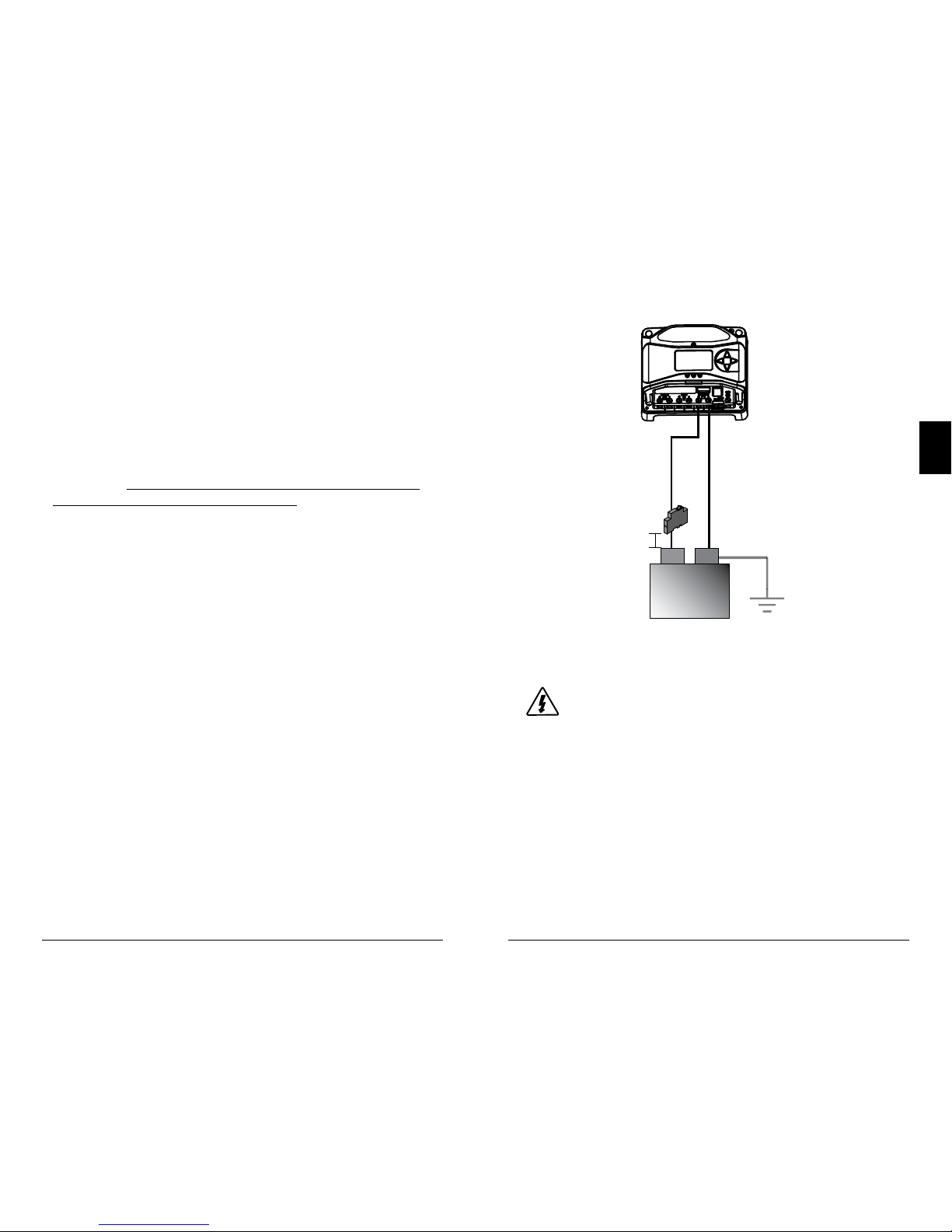
STEP 4: Battery Connections - see diagram below
Be sure that DIP switches 2 and 3 are set for 12 or 24V, as
described in Section 3.2
NOTE: Before connecting the battery, measure the open-circuit
voltage. It must be over 10 volts to start the controller. If the
system voltage Settings Switches are set to Auto-detect, battery
voltage over 15.5V will be detected as a 24V nominal battery, and
the unit will charge accordingly. The 12/24V auto selection is only
done at start-up.
With the battery disconnect open, connect the battery (+)
and (-) wires from the battery to controller. DO NOT CLOSE
THE BREAKER AT THIS TIME.
15 cm
MAX.
BATTERY (-)
BATTERY (+)
+
-
(at battery
OR solar side,
but NOT both)
System Ground
12V / 24V
BATTERY
Fuse or breaker sizing
based on required wire
ampacity
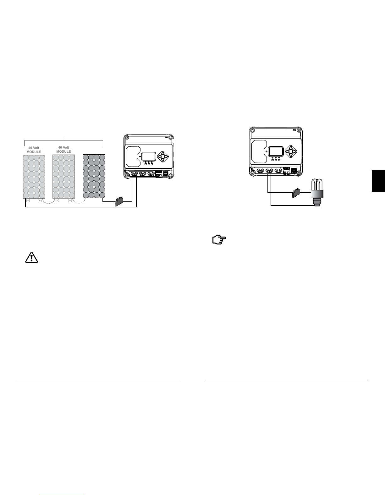
STEP 5: Solar Connections - see diagram below
WARNING: Shock Hazard
The solar PV array can produce open-circuit voltages
in excess of 120 Vdc when in sunlight. Verify that the
solar input breaker or disconnect has been opened
(disconnected) before installing the system wires.
With the solar disconnect open, connect the solar (PV) array
wires to the EcoBoost MPPT solar terminals. Use caution,
since the solar array will produce current whenever in
sunlight. A solar disconnnect is a convenient way to break
the PV connection when necessary. DO NOT CLOSE THE
BREAKER AT THIS TIME.
Installation
EcoBoost MPPT Operator’s Manual
2120
3.0
40 Volt
MODULE
40 Volt
MODULE
40 Volt
MODULE
SOLAR (+)
Solar
Disconnect
SOLAR (-)
(+)
(+)
(+)
(-)
(-)
(-)
120Voc Maximum
Fuse or breaker sizing
based on required wire
ampacity
STEP 6: Load Connections - see diagram below
CAUTION: Equipment Damage
Do not wire any AC inverter to the load terminals of the
EcoBoost MPPT. Damage to the load control circuit may result.
An inverter should be wired to the battery. If there is a possibility
that any other load will sometimes exceed the EcoBoost’s
maximum voltage or current limits, the device should be wired
directly to the battery or battery bank. If load control is required,
contact Morningstar Tech Support for assistance.
Turn the loads off, and connect the load wires to the load
terminals. DO NOT CLOSE THE BREAKER AT THIS TIME.
LOAD (+)
LOAD (-)
Fuse or breaker sizing based
on required wire ampacity
STEP 7: Power-Up and Verify System Operation
NOTE: Carefully observe the LEDs after each
connection. The LEDs will indicate proper polarity and
a good connection.
Close the battery breaker to power on the controller. Watch
the the charging status, and then the three battery stateof-charge (SOC) LEDs blink in sequence (G-Y-R), confirm
ing proper start-up. If they do not light, check the battery
polarity (+/–) and battery voltage.
Next, the green, yellow or red LED will light depending on
the battery state-of-charge (SOC). Confirm that one of these
LEDs is on before going to the next step.
Close the solar disconnect. If the solar input is connected
while in sunlight, the charging LED indicator will light.
Confirm proper connection by observing the charging LED.
Close the load disconnect, and turn the load on, to confirm
a proper connection.
If the load does not turn on, it could be for various reasons:

EcoBoost MPPT Operator's Manual
23
4.0
Installation
22
• the EcoBoost MPPT is in LVD (red LED on)
• there is a short circuit in the load (LEDs blinking R/G – Y)
• there is an overload condition (LEDs blinking R/Y - G)
• the load is not connected, not working, or turned off
After all connections have been completed, observe the
LEDs to make sure the controller is operating normally for
system conditions. If the optional digital meter is used,
observe that the display is scrolling with proper voltage
and current values. Also, a self- test can be performed with
digital meter units.
STEP 8: To Power-down
WARNING: Risk of Damage
ONLY disconnect the battery from the
EcoBoost MPPT AFTER the solar input has been
disconnected. Damage to the controller may result if the
battery is removed while the EcoBoost MPPT is charging.
• To prevent damage, power-down must be done in the
reverse order as power-up.
4.1 TrakStarTM MPPT Technology
The EcoBoost MPPT utilizes Morningstar’s TrakStar
Maximum Power Point Tracking technology to extract
maximum power from the solar module(s). The tracking
algorithm is fully automatic and does not require user
adjustment. TrakStar technology will track the array
maximum power point voltage (Vmp) as it varies with
weather conditions, ensuring that maximum power is
harvested from the array through the course of the day.
High Voltage Strings and Grid-tie Modules
Another benefit of TrakStar MPPT technology is the ability
to charge 12 or 24 Volt batteries with solar arrays of higher
nominal voltages. A 12 Volt battery bank can be charged
with a 12, 24, 36 or 48V nominal off-grid solar array.
Certain grid-tie solar modules may also be used if the solar
array open circuit voltage (V
oc
) rating will not exceed the
EcoBoost MPPT 120V maximum input voltage rating at
worst-case (lowest) module temperature. The solar module
documentation should provide V
oc
vs. temperature data.
Higher solar input voltage results in lower solar input current
for a given input power. High voltage solar input strings
allow for smaller gauge solar wiring. This is especially helpful
for systems with long wiring runs between the solar array
and the EcoBoost MPPT.
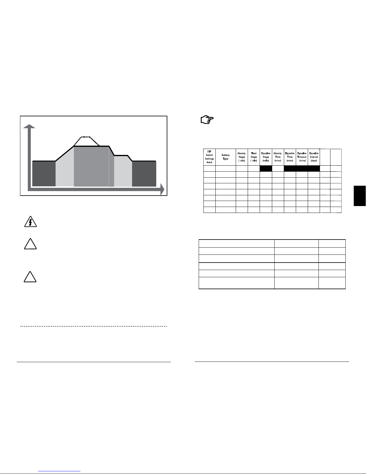
4.2 Battery Charging
4-Stage Charging
The EcoBoost MPPT has a 4-stage battery charging
algorithm for rapid, efficient, and safe battery charging.
Figure 4-1 shows the sequence of stages.
4.0 OPERATION
Operation
EcoBoost MPPT Operator's Manual
25
24
4.0
NIGHT
NIGHT
BULK
CHARGE
ABSORPTION
FLOAT
EQUALIZE
VOLTAGE
TIME
Figure 4-1. EcoBoost MPPT Charging Algorithm
WARNING: Risk of Explosion
Equalizing vented batteries produces explosive gases.
The battery bank must be properly ventilated.
CAUTION: Equipment Damage
Equalization increases the battery voltage to levels that
may damage sensitive DC loads. Verify all system loads
are rated for the temperature compensated Equalize
voltage before beginning an Equalization charge.
CAUTION: Equipment Damage
Excessive overcharging and gasing too vigorously can
damage the battery plates and cause shedding of active
material from the plates. An equalization that is too
high or for too long can be damaging. Review the
requirements for the particular battery being used in
your system.
Battery Charge Settings
Preset EcoBoost MPPT battery charging options are shown
in tables 4-1 and 4-2 below. All voltage settings listed are
for nominal 12 Volt batteries. Multiply the voltage settings
by two (2) for 24 Volt batteries.
!
!
NOTE: These settings are general guidelines for
use at the operator’s discretion. The EcoBoost MPPT
can be programmed to satisfy a wide range of charging
parameters. Consult the battery manufacturer for optimal
battery charge settings.
DIP
S
witch
S
etting s
4
-5-6
B
attery
T
ype
A
bsorp.
S
tage
(
volts)
F
loat
S
tage
(
volts)
E
qualiz e
S
tage
(
volts)
A
bsorp.
T
ime
(
mins)
E
qualiz e
T
ime
(
mins)
E
qualiz e
T
imeout
(
mins)
E
qualiz e
Equaliz e
Equaliz e
I
nterva l
(
days)
Equaliz e
Interv al
(days)
Equaliz e
Interv al
(days)
off-off-off 1 - Sealed* 14.00 13.50
150
off-off-on 2 - Sealed* 14.15 13.50 14.40 150 60 120 28
off-on-off 3 - Sealed* 14.30 13.50 14.60 150 60 120 28
off-on-on 4- AGM/Flooded 14.4 0 13.50 15.10 180 120 180 28
on-off-off 5 - Flooded 14.60 13.50 15.30 180 120 180 28
on-off-on 6 - Flooded 14.70 13.50 15.40 180 180 240 28
on-on-off 7 - L-16 15.40 13.40 16.00 180 180 240 14
on-on-on 8 - Custom Custom Custom Custom Custom Custom Custom Custom
Custom Custom
Custom
* “Sealed” baery type includes gel and AGM baeries
Custom
LVD
(volts)
LVR
(volts)
Custom
12.30
13.80
12.10 13.60
11.90
13.40
11.50
13.00
11.70
13.20
11.30
12.80
11.50
12.60
Table 4.1. Battery charging settings for each selectable battery type
Absorption Extension Voltage 12.50 Volts
Absorption Extension Time Absorption Time + 30 minutes
Float Exit Time-out 30 minutes
Float Cancel Voltage 12.30 Volts
Equalize Time-out Equalize Time + 60 minutes
Temperature Compensation Co-efficient - 30
millivolts / °C
/ 12V
Table 4.2. Battery settings that are shared among all battery types
Operation
EcoBoost MPPT Operator's Manual
27
26
4.0
4.3 Load Control Information
The primary purpose of the load control function is to
disconnect system loads when the battery has discharged to
a low state of charge, and to reconnect system loads when
the battery is sufficiently recharged. System loads may be
lights, DC appliances, or other electronic devices. The total
current draw of all loads must not exceed maximum load
ratings of 20 Amps (EB-20/M) or 30 Amps (EB- 30/M or EB40/M).
CAUTION: Equipment Damage
Do not wire any AC inverter to the load terminals of the
EcoBoost. Damage to the load control circuit may result. An
inverter should be wired to the battery. If there is a possibility
that any other load will sometimes exceed the EcoBoost MPPT's
maximum voltage or current limits, the device should be wired
directly to the battery or battery bank. If load control is required,
contact Morningstar Tech Support for assistance.
Current Compensation:
All LVD and LVR set-points are current compensated.
Under load, the battery voltage will sag in proportion to the
current draw of the load. Without the current compensation
feature, a short-term large load could cause a premature
LVD. LVD and LVR set-points are adjusted lower per the
following table:
System Voltage
Current Compensation
12 Volt -15 mV per amp of load
24 Volt -30 mV per amp of load
Table 4-3. Current Compensation Values
LVD Warning:
As the battery discharges, the Battery Status LEDs will
transition from green to yellow and then from yellow to
flashing red. The flashing red indication is a warning that a
low voltage disconnect (LVD) event will occur soon.
The amount of time between a green SOC indication and
load disconnect will depend on many factors including:
• rate of discharge (amount of load draw)
• capacity of the battery
• health of the battery
• LVD set-point
If the battery discharges to the LVD set-point the load will
disconnect and a solid red Battery Status LED indication will
be displayed.
General Load Control Notes:
Do not wire multiple EcoBoost MPPT load outputs together
in parallel to power DC loads with a current draw greater
than 20 or 30A, depending on the EcoBoost MPPT model in
use. Equal current sharing cannot be assured and an overload condition will likely occur on one or more controllers.
CAUTION: Equipment Damage
Exercise caution when connecting loads with
specific polarity to a live load circuit. A reverse polarity
connection may damage the load. Always double check
load connections before applying power.

Operation
EcoBoost MPPT Operator's Manual
29
28
4.0
4.4 LED Indications
KEY:
G = green G - Y - R = flashing sequencially
Y = yellow G / Y = flashing together
R = red G / Y - R = G and Y flashing together,
alternating with R flash
4.4.1. Power-up
Normal power-up: Status LED flashes G, then SOC LEDS
flash G - Y - R, then SOC LEDs indicate battery charge status
with a single battery status LED.
Failed bootload: Status LED flashes G, then SOC LEDS
flash G - Y and stop on solid Y.
4.4.2 Status LED
The Status LED indicates charging status and any existing solar input error conditions. The Status LED is on when
charging during the day and off at night. The Status LED will
flash red whenever an error condition(s) exists. Table 4.4 lists
the Status LED indications.
Color Indication
Operating
State
None
Off (with heart-
beat¹)
Night
Green
On Solid
( with heart-
beat² )
Charging
Red Flashing Error
Red
On Solid
( with heart-
beat
2
)
Critical Error
¹ heartbeat indication flickers the Status LED on briefly every 5 seconds
² heartbeat indication flickers the Status LED off briefly every 5 seconds
Table 4.4. Status LED Definitions
NOTES:
1) R flashing is generally a user addressable fault / error
2) R charging status LED ON with heartbeat blink OFF
every 5 secs is a critical fault that generally requires service.
See, "Solid Charging Status LED with Self-test (R-Y-G) SOC
Faults", in Section 5.1.
4.4.3 State-of-Charge LEDs
Battery SOC LED Indications are shown in Table 4-5 below:
Condition Indication
Absorption G flash - every sec
Float
G flash - every 2 secs
Equalize
G flash - 2 / sec
SOC > 13.5V
G solid
13.5V > SOC > 13.0V
G / Y solid
13.0V > SOC > 12.5V
Y solid
SOC < 12.5V
Y / R solid
Low voltage disconnect warning
R flash - every sec
Low voltage disconnect
R solid
Table 4.5. Battery SOC LED Indications
4.5 Alarms
Solar Overload
No LED indication. The EcoBoost MPPT will limit battery
current to the 20, 30 or 40 amp maximum rating. An oversized solar array will not operate at peak power. The solar
array should be less than the EcoBoost MPPT nominal max.
input power rating for optimal performance. See Section
7.0 - Technical Specifications for more information.
Operation
EcoBoost MPPT Operator's Manual
31
30
4.0
High Temperature Current Limit
The EcoBoost MPPT will limit the solar input current if the
heatsink temperature exceeds safe limits. Solar charge
current will be tapered back (to 0 amps if needed) to reduce
the heatsink temperature. The EcoBoost MPPT is designed
to operate at full rated current at the maximum ambient
temperature. This alarm indicates that there is insufficient
airflow and that the heatsink temperature is approaching
unsafe limits. If the controller frequently reports this alarm
condition, corrective action must be taken to provide better
air flow or to re-locate the controller to a cooler spot.
High Input Voltage Current Limit
The EcoBoost MPPT will limit the solar input current as
the solar array Voc approaches the maximum input voltge
rating. The array Voc should never exceed the 120 volt
maximum input voltage - see the array voltage de-rating
graph in Appendix.
Current Limit
The array power exceeds the rating of the controller. This
alarm indicates that the EcoBoost MPPT is limiting battery
current to the maximum current rating.
RTS Open
The Remote Temperature Sensor is not connected to the
controller. Use of the RTS is recommended for proper
battery charging.
Heatsink Temperature Sensor Open / Shorted
The heatsink temperature sensor is damaged. Return the
controller to an authorized Morningstar dealer for service.
Uncalibrated
The controller was not factory calibrated. Return the
controller to an authorized Morningstar dealer for service.
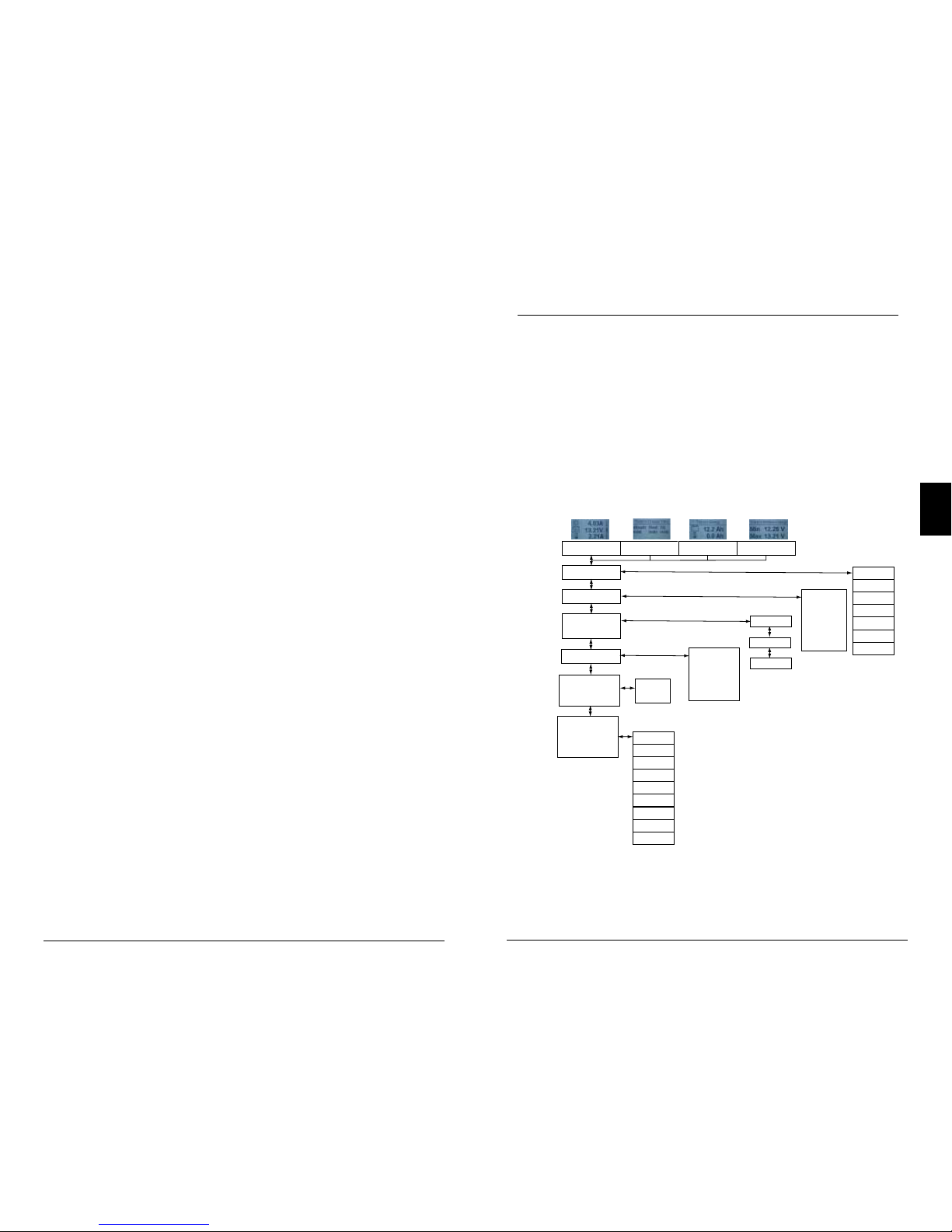
4.6 Custom Settings
4.6.1 Adjusting Set-points with the Meter Display
The EcoBoost MPPT is available in metered and
non-metered versions. The metered model allows:
• Custom programming directly from the unit.
• Extensive settings adjustment and information as shown
partially in Figure 4-2 below.
Figure 4-2. Simplified Meter Map.
Start Lighting Test
Load Disconnect
Factory Reset
Reset Control
Backlight Timer
Backlight
Target Voltage
Battery Temp.
Display Screens and P rogra mming
Models:
EcoBoost-20M
EcoBoost-40M
EcoBoost-30M
Main Screens
Daily Charging Stage - Time
Daily Charge Transferred -
Battery and Load
Solar Current - Battery
Current - Load Current
Daily Max / Min
Battery Voltages
STATUS
HISTORY
See Complete History
Screens Online, or in
Manual Insert
SYSTEM
DISPLAY
SETTINGS
COMMANDS
Faults
Load / Light State
Charge State
Input Voltage
Alarms
CUSTOM PROGRAMMING:
To
Programming
Screens
Clear KWh
Records
Graphs
Error Log
Battery Sense
Hour Meter
Last Equalization
Brightness
Auto Scroll
Contrast
Auto Return
Auto Scroll Timer
Language
Temp. Units
See Complete
Programming Screens
Online or in Manual Insert
See Complete
Programming Screens
Online or in Manual Insert
Clear Resettable Ah
Clear Total Ah
Serial No.
Firmware Version
Battery Type
Absorption Voltage
Float Voltage
EQ Voltage
Input Mode
System Voltage
Operation
EcoBoost MPPT Operator's Manual
33
32
4.0
For metered models, see the included complete meter
map insert, also available in the EcoBoost MPPT support
documents at:
www.morningstarcorp.com
4.6.2 Meter Display Operation
4.6.2.1 Directional Key Use and Operation / Navigating
the Meter Map
The EcoBoost MPPT's meter map consists of two main
axes: The horizontal top level daily monitoring screens, and
the vertical Main Menu stacked screens. The four lighted
triangular directional control keys allow movement to reach
any desired point on the meter map. A lit key indicates
a valid direction in the map. The current location is
indicated on the display with a column heading, and a bold
descriptor.
4.6.2.2 Adjusting the Meter Display
The display setting options, as shown in Figure 4-2, are
adjustable by using the directional keys to locate and edit a
desired setting or variable.
4.7 Data Logging (future use)
The EcoBoost MPPT logs thirty days of basic system data:
• Daily minimum battery voltage
• Daily maximum battery voltage
• Daily Events (Equalize triggered, Entered Float, Alarm/
Fault occurred, Reset)
• Faults / Alarms - recorded only if a fault or alarm occurs
that day
• Daily charge to battery
The EcoBoost MPPT USB Micro-B port (for future use) will
allow data transfer in mobile applications.
4.8 Auxilliary USB Charging
1) The EcoBoost MPPT has two USB-A ports for use as
charging sources for small electronics. Energy is taken from
the system battery, so any auxilliary charging must be balanced with other load draws on the system battery.
2) The USB charging ports will operate in all conditions
except for LVD, HVD, or a user requested Load Disconnect
(from a meter command, for example). In LVD, HVD & Load
Disconnect, the main load and the USB ports are powered
off.
3) If the main load gets faulted for some reason (shorted
FET, etc), the USB charging ports will still operate.
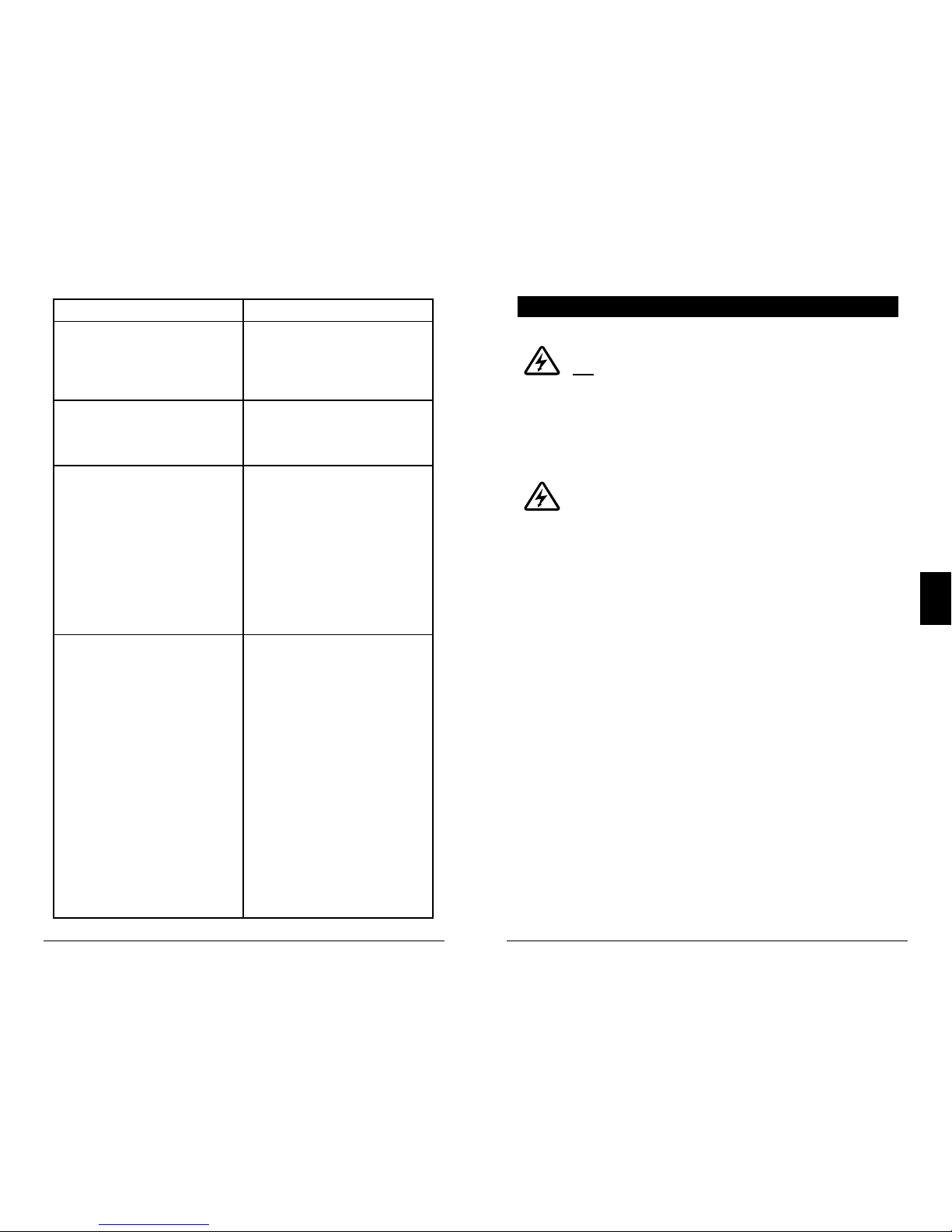
4.9 Inspection and Maintenance
Table 4-6 below lists the recommended maintenance
schedule to keep your EcoBoost MPPT performing
optimally.
WARNING: RISK OF ELECTRICAL SHOCK.
NO POWER OR ACCESSORY TERMINALS ARE ELEC-
TRICALLY ISOLATED FROM DC INPUT, AND MAY BE ENERGIZED WITH HAZARDOUS SOLAR VOLTAGE. UNDER CERTAIN
FAULT CONDITIONS, BATTERY COULD BECOME OVERCHARGED. TEST BETWEEN ALL TERMINALS AND GROUND
BEFORE TOUCHING.
WARNING: SHOCK HAZARD
DISCONNECT ALL POWER SOURCES TO THE
CONTROLLER BEFORE REMOVING THE WIRING BOX
COVER. NEVER REMOVE THE COVER WHEN VOLTAGE
EXISTS ON THE ECOBOOST MPPT POWER CONNECTIONS.
EcoBoost MPPT Operator’s Manual
35
5.0
Operation
34
Schedule Maintenance Items
2 weeks after installation
Re-tighten power terminal
connections to specified
torque values.
3 months after installation
Re-tighten power terminal
connections to specified
torque values.
Monthly or After Each
Equalization
Inspect the battery bank.
Look for cracked or
bulging cases, and corroded
terminals.
For wet cell (flooded type)
batteries, make sure the
water level is correct. Wet
cell water levels should be
checked monthly or accord
-
ing to the manufacturer’s
recommendations.
Annually
Clean the heatsink fins with a
clean, dry rag.
Inspect all wiring for
damage or fraying.
Inspect for nesting insects.
Re-tighten all wiring terminal
connections to specified
torque values.
Inspect the system earth
grounding for all
components. Verify all
grounding conductors are
appropriately secured to
earth ground.
Table 4-6. Maintenance Schedule
WARNING: RISK OF ELECTRICAL SHOCK.
NO POWER OR ACCESSORY TERMINALS ARE ELEC-
TRICALLY ISOLATED FROM DC INPUT, AND MAY BE ENERGIZED WITH HAZARDOUS SOLAR VOLTAGE. UNDER CERTAIN
FAULT CONDITIONS, BATTERY COULD BECOME OVERCHARGED. TEST BETWEEN ALL TERMINALS AND GROUND
BEFORE TOUCHING.
WARNING: SHOCK HAZARD
A MEANS OF DISCONNECTING ALL POWER SUPPLY
POLES MUST BE PROVIDED. THESE DISCONNECTS
MUST BE INCORPORATED IN THE FIXED WIRING. OPEN
ALL POWER SOURCE DISCONNECTS BEFORE REMOVING
CONTROLLER WIRING COVER, OR ACCESSING WIRING.
5.1 LED Fault Indications
Load Over-current
Error Status LED: Flashing red. Battery status LEDs: R/YG sequencing. If the load current exceeds the maximum
load current rating, the EcoBoost MPPT will disconnect the
load. The greater the overload the faster the load will be
disconnected. A small overload could take a few minutes to
disconnect. The EcoBoost MPPT will attempt to reconnect
the load two (2) times. Each attempt is approximately 10
seconds apart. If the overload remains after two (2)
attempts, the load will remain disconnected until power is
removed and re-applied.
Solar Short Circuit
Charging Status LED: OFF. Solar input power wires are
short-circuited. Charging automatically resumes when the
short is cleared.
Battery Reverse Polarity
No LED indication, the unit is not powered. No damage to
the controller will result. Correct the miswire to resume
normal operation.
5.0 TROUBLESHOOTING

Troubleshooting
EcoBoost MPPT Operator’s Manual
3736
5.0
Load Short Circuit
Error status LED: Flashing red. Battery status LEDs: R/G-Y
sequencing. Fully protected against load wiring shortcircuits. After two (2) automatic load reconnect attempts (10
seconds between each attempt) the EcoBoost MPPT will
wait, and then automatically reconnect the load, once the
short is cleared.
High Solar Voltage Disconnect
Charging Status LED: R flashing. No battery status errors.
If the solar input open-circuit voltage (Voc) exceeds the 120
volt maximum rating, the array will remain disconnected
until the Voc falls safely below the maximum rating.
Remote Temperature Sensor (RTS)
Error status LED: Flashing red. Battery status LEDs: R/Y G/Y sequencing. A bad RTS connection or a severed RTS
wire has disconnected the temperature sensor during
charging. Charging automatically resumes when the
problem is fixed. To resume operation without an RTS,
disconnect all power to the EcoBoost MPPT and then
reconnect. If the controller is re-started with the failure
still present, the controller may not detect that the RTS is
connected, and the LEDs will not indicate a fault.
A metered model, an RM-1 meter, or MSView PC software
can be used to determine if the RTS is working properly.
Battery / Load High Voltage Disconnect (HVD)
Error status LED: Flashing red. Battery status LEDs: R-G
sequencing. This fault is set when battery voltage is above
normal operating limits. The controller will disconnect the
solar input and set a High Voltage Disconnect fault. This
fault is commonly caused by other charging sources in the
system, charging the battery above the EcoBoost MPPT
regulation voltage. Recovery occurs at HVD re-connect
threshold, and the fault will automatically clear. See Section
7 - Technical Specifications for values.
High Heatsink Temperature
Error status LED: Flashing red. Battery status LEDs: R-Y
sequencing. The heatsink temperature has exceeded safe
limits and the load is disconnected. The load will automatically reconnect when the heatsink cools to a safe
temperature.
Battery Over-current
Error status LED: Flashing red. Battery status LEDs:
R/Y-G sequencing. While rare, if battery current exceeds
approximately 130% of the controller’s output current
rating, this fault can occur. The fault is generally related
to fast, large battery voltage transients (connecting a very
heavy or capacitive load like an inverter) that are faster
than the controller can regulate, and it shuts off to protect
the circuitry. The controller will automatically re-start in 10
seconds.
Settings (DIP) Switch Changed
Error status LED: Flashing red. Battery status LEDs:
R-Y-G sequencing. If a settings switch is changed while
there is power to the controller, the LEDs will begin
sequencing and the solar input will disconnect. The
controller must be re-started to clear the fault and begin
operation with the new settings.
Custom Settings Edit
Error status LED: Flashing red. Battery status LEDs: R-Y-G
sequencing. A value has been modified in custom settings
memory. The controller will stop charging and indicate a
fault condition. After all settings have been modified, the
controller must be reset by removing and then restoring
power to the controller. The new programmed settings will
be used after the power reset.

Troubleshooting
EcoBoost MPPT Operator’s Manual
3938
5.0
Firmware Update Failure
The firmware update was not successfully programmed. The
controller will not indicate the full power-up LED sequence
of G-Y-R when power to the controller is reset. Instead, the
controller will display green, and then stop on yellow. The
yellow LED will continue to be lit and the controller will not
complete start up or begin charging.
Re-try the firmware update. The firmware must be
successfully loaded before the controller will start up.
SOLID CHARGING STATUS LED with SELF-TEST (R-Y-G)
SOC FAULTS
Verify that nothing has been mis-wired. If not, the error is
likely critical. Contact an authorized Morningstar dealer for
support.
Fault Charging Status LED Battery SOC LEDs
PV FET Short Solid red R-Y-G sequencing
Load FET Short Solid red R-Y-G sequencing
Load FET Open Solid red R-Y-G sequencing
Damaged local
temperature sensor
Solid red (only if RTS
is invalid)
R-Y-G sequencing
Damaged heatsink
temperature sensor
Solid red R-Y-G sequencing
Software Solid red R-Y-G sequencing
RE-SETTABLE SELF-TEST (R-Y-G) SOC FAULTS
Fault - Battery SOC LEDs
Custom Settings Edit - R-Y-G sequencing
DIP Switch Change - R-Y-G sequencing
5.2 Battery Charging and Performance Issues
Problem:
No LED indications, controller does not appear to be
powered
Solution:
With a multi-meter, check the voltage at the battery
terminals on the EcoBoost MPPT. Battery voltage must be
10 vdc or greater. If the voltage on the battery terminals of
the controller is between 10 and 35 vdc, and no LEDs are lit,
contact your authorized Morningstar dealer for service.
If no voltage is measured, check wiring connections, fuses,
and breakers.
Problem:
The EcoBoost MPPT is not charging the battery.
Solution:
Check the three (3) battery SOC LEDs. If they are flashing in
a sequence, see Section 4.5 LED indications of this manual
to determine the cause. A metered model, an RM-1 meter,
or MSView PC software will display active faults and alarms.
If the LED indications are normal, check the fuses,
breakers, and wiring connections in the power source wiring.
With a multi-meter, check the array voltage directly at the
EcoBoost MPPT solar input terminals. Input voltage must be
greater than battery voltage before charging will begin.
Problem:
Controller makes buzzing and humming noises.
Solution:
No action is required. This is expected due to magnetic
resonance and circuit switching.
If troubleshooting does not correct the problem, please
refer to Morningstar's Warranty Claim Procedure in
Section 6.

41
EcoBoost MPPT Operator’s Manual
7.0
Warranty and Policies
40
LIMITED WARRANTY Morningstar Solar Controllers and Inverters
The EcoBoost MPPT is warrantied to be free from defects in
material and workmanship for a period of TWO (2) years from the
date of shipment to the original end user. Morningstar will, at its
option, repair or replace any such defective products.
WARRANTY EXCLUSIONS AND LIMITATIONS:
This warranty does not apply under the following conditions:
♦ Damage by accident, negligence, abuse or improper use
♦ PV or load currents exceeding the ratings of the product
♦ Unauthorized product modification or attempted repair
♦ Damage occurring during shipment
♦ Damage results from acts of nature such as lightning and
weather extremes
THE WARRANTY AND REMEDIES SET FORTH ABOVE ARE
EXCLUSIVE AND IN LIEU OF ALL OTHERS, EXPRESS OR
IMPLIED. MORNINGSTAR SPECIFICALLY DISCLAIMS ANY
AND ALL IMPLIED WARRANTIES, INCLUDING, WITHOUT
LIMITATION, WARRANTIES OF MERCHANTABILITY AND
FITNESS FOR A PARTICULAR PURPOSE. NO MORNINGSTAR
DISTRIBUTOR, AGENT OR EMPLOYEE IS AUTHORIZED
TO MAKE ANY MODIFICATION OR EXTENSION TO THIS
WARRANTY.
MORNINGSTAR IS NOT RESPONSIBLE FOR INCIDENTAL OR
CONSEQUENTIAL DAMAGES OF ANY KIND, INCLUDING BUT
NOT LIMITED TO LOST PROFITS, DOWN-TIME, GOODWILL OR
DAMAGE TO EQUIPMENT OR PROPERTY.
6.0 WARRANTY
R15-8/15
EB-MPPT-20/M EB-MPPT-30/M EB-MPPT-40/M
Electrical:
Nominal Battery Voltage 12 volts or 24 volts (all)
Battery Voltage Range 10-35 volts (all)
Voltage Accuracy 0.1% +/- 50mV (all)
Max. Battery Current 20 Amps 30 Amps 40 Amps
Max. PV Open-Circuit Voltage All: 120 Volts
Load Current Rating 20 Amps 30 Amps 30 Amps
Self Consumption < 25mA (no meter) <40mA (meter)
LED Indications (1) status, (3) battery SOC
Transient Surge Protection 4500 watts (solar, battery, load)
Conversion Efficiency (peak) 97.3% (all)
Mechanical:
Dimensions (cm) 19.6(W) x 18.1(L) x 7.1(D)
Weight (kg) 1.4
Wire Size Range:
Power Terminals 2.5 - 16 mm2 / #14 - 2 AWG
(maximum torque) 3.95 Nm
Temp. Sense 0.25 - 1.0 mm2 / #24 - 16 AWG
Enclosure IP20, Type 1
Battery Charging:
4-Stage Charging: Bulk, Absorption, Float, Equalize
Temperature compensation
Coefficient: -30mV / 12 volt / ºC
Temperature compensated
set-points: Absorption, Float, Equalize, HVD
and HVDR (solar)
7.0 TECHNICAL SPECIFICATIONS

Technical Specifications
43
42
EcoBoost MPPT Operator’s Manual
7.0
Battery Charging Set-points (@ 25°C):
[multiply voltages by (2) for 24 volt systems]
Current Compensation:
12 Volt systems -15 mV / A
24 Volt systems -30 mV / A
Compensated set-points LVD
Compensation threshold 3A
Load and Solar Control (multiply voltages by (2) for 24 volt
systems)
:
Default values (customizable)
LVD / USB charging See table above
LVR See table above
Instant LVD 10.0V
HVD - solar Current stage set-point
+ 0.5V (@ 25ºC)
HVD - load / USB charging 15.3V
HVDR - solar 13.8V (@ 25ºC)
HVDR - load USB charging 14.5V
LVD Warning 10 minutes
LVD Override 10 minutes
Maximum # LVD overrides No limit unless
(not customizable) V_batt < Instant LVD
DIP
S
witch
S
etting s
4
-5-6
B
attery
T
ype
A
bsorp.
S
tage
(
volts)
F
loat
S
tage
(
volts)
E
qualiz e
S
tage
(
volts)
A
bsorp.
T
ime
(
mins)
E
qualiz e
T
ime
(
mins)
E
qualiz e
T
imeout
(
mins)
E
qualiz e
Equaliz e
Equaliz e
I
nterval
(
days)
Equaliz e
Interva l
(days)
Equaliz e
Interva l
(days)
off-off-off 1 - Sealed* 14.00 13.50
150
off-off-on 2 - Seal ed* 14.15 13.50 14.40 150 60 120 28
off-on-off 3 - Seal ed* 14.30 13.50 14.60 150 60 120 28
off-on-on 4- AGM/Flooded 14.40 13.50 15.10 180 120 180 28
on-off-off 5 - Flood ed 14.60 13.50 15.30 180 120 180 28
on-off-on 6 - Flooded 14.70 13.50 15.40 180 180 240 28
on-on-off 7 - L-16 15.40 13.40 16.00 180 180 240 14
on-on-on 8 - Custom Custom Custom Custom Custom Custom Custom Cu stom
Custom Cust om
Custom
* “Sealed” baery type includes gel and AGM baeries
Custom
LVD
(volts)
LVR
(volts)
Custom
12.30
13.80
12.10 13.60
11.90
13.40
11.50
13.00
11.70
13.20
11.30
12.80
11.50
12.60
Lighting Control (DIP 1 ON):
Lighting Timer Setting Dusk-Dawn (default)
Lighting Test Timer 5 minutes
Data & Communications:
Data Port (future use) USB Micro-B
Datalogging (future use) 30-day maximum
Comm. Protocol Serial
Digital Meter:
Resolution 128 x 64
Viewing Area 70mm x 40mm
Display Color blue on white
Backlight LED
Operating Temperature -20ºC to +60ºC
Storage Temperature -30ºC to +80ºC
Environmental:
Maximum Operating Altitude 2000 meters
Operating Temperature -40ºC to +60ºC
Storage Temperature -40ºC to +80ºC
Humidity 100% n.c.
Tropicalization Conformally coated PCBs;
Marine-rated terminals
Protections
Power-up against any active faults
Reverse Polarity - battery and array
Solar Short-Circuit
Solar High Voltage Disconnect
High Heatsink Temperature - Current De-rating
High Heatsink Temperature - Load Disconnect
Load Short-Circuit
Load Over-Current
Heatsink Temperature Limit
RTS Terminals
Certifications
44
8.0 CERTIFICATIONS
• Complies with CSA-C22.2 No. 107.1
• IEC 62109-1
• FCC Class B compliant
ENs Directives:
• Complies with ENs and LVD standards for CE marking
• EN 62109-1
• Emissions 55014-1
• Immunity 55014-2
EcoBoost MPPT
TM
is a trademark of Morningstar
Corporation
©2018 Morningstar Corporation. All rights reserved.
MS-002243 v2.3
REACH
ALL
COMPONENTS
COMPLIANT
Registration, Evaluation and
Authorization of Chemicals
TUVRheinland
®
CERTIFIED
IEC 62109-1
EN 62109-1
www.tuv.com
ID 0007000000
www.morningstarcorp.com
MAXIMUM POWER POINT TRACKING
Régulateur de charge solaire
Solarladesystem-Regler
Controlador del sistema de carga solar
Manuel de l’utilisateur...46
Bedienerhandbuch.........87
Manual del operador......128
Le présent document est un manuel abrégé. Pour consulter lemanuel intégral
du produit, veuillez vous référer à la version papier en anglais ou à la version
électronique sur:
www.morningstarcorp.com
Dieses Handbuch wurde gekürzt. Das vollständige Produkthandbuch finden Sie in
der gedruckten englischen Version des Handbuchs oder in elektronischer Version
unter: www.morningstarcorp.com
Este es un manual resumido. Para consultar el manual completo del producto,
consulte la versión impresa en inglés del manual ola versión que se encuentra en:
www.morningstarcorp.com
MODELS
EB-MPPT-20 EB-MPPT-20M
EB-MPPT-30 EB-MPPT-30M
EB-MPPT-40 EB-MPPT-40M
EcoBoost MPPT
TM
Manuel de l’utilisateur EcoBoost MPPT
4746
1.0
FRANÇAIS
SYNTHÈSE DES SPÉCIFICATIONS
EB-MPPT-20 EB-MPPT-30 EB-MPPT-40
Tension nominale
dela batterie
12/24V 12/24V 12/24V
Tension maximale en
circuit ouvert du
système PV*
120V 120V 120V
Puissance d’entrée
nominale maximale**
300/600W 400/800W 560/1120W
Courant maximal de
charge de la batterie
20A 30A 40A
Courant de
charge nominal
20A 30A 30A
DIMENSIONS (centimètres)
**Les niveaux de puissance indiqués correspondent à la puissance
maximale pouvant être prise en charge par le PS-MPPT. Il est possible
d'utiliser des générateurs plus puissants sans endommager le régulateur.
*La tension du générateur ne doit jamais excéder cette limite.
( 19,6 )
( 17,0 )
( 18,1 )
( 14,8 )
( 7,1 )
1.0 CONSIGNES DE SÉCURITÉ
IMPORTANTES
CONSERVEZ CES INSTRUCTIONS.
Le présent manuel contient des consignes de sécurité et des
instructions d'installation et d'utilisation importantes pour
lerégulateur de charge solaire EcoBoost MPPT.
Les symboles suivants sont utilisés tout au long du présent
manuel pour signaler les situations potentiellement dangereuses
ou souligner les consignes de sécurité importantes:
ATTENTION: signale une situation potentiellement
dangereuse. Faites preuve d’une extrême prudence pour
effectuer cette tâche.
MISE EN GARDE: signale une procédure essentielle pour
l’utilisation sûre et adéquate du régulateur.
REMARQUE: signale une procédure ou une fonction
importante pour l’utilisation sûre et adéquate durégulateur.
Informations relatives à la sécurité
• Veuillez lire l’intégralité des instructions et des mises
en garde contenues dans le présent manuel avant
deprocéder à l’installation.
• Le EcoBoost MPPT ne contient aucune pièce susceptible
d'être réparée par l'utilisateur. Ne démontez pas le
régulateur et n'essayez pas de le réparer.
ATTENTION: risque d’électrocution.
AUCUNE BORNE ACCESSOIRE OU D’ALIMENTATION
N’EST ISOLÉE ÉLECTRIQUEMENT DE L’ENTRÉE DC.
ELLES PEUVENT DONC ÊTRE SOUMISES À UNE
TENSION SOLAIRE DANGEREUSE. DANS CERTAINS
CAS DE DÉFAILLANCE, LA BATTERIE POURRAIT SUBIR
UNE SURCHARGE. EFFECTUEZ UN TEST ENTRE
TOUTES LES BORNES ET LA MISE À LA TERRE AVANT
TOUTE MANIPULATION.
ATTENTION: LE PORT DE COMMUNICATION DOIT
ÊTRE DVCB. UNE ISOLATION EXTERNE EST REQUISE
SI ELLE EST CONNECTÉE À UN CIRCUIT DVCA.
Consignes de sécurité importantes
Manuel de l’utilisateur EcoBoost MPPT
4948
1.0
FRANÇAIS
• L’utilisation d’un sectionneur solaire et d’un sectionneur
de batterie externes est requise.
• Débranchez toutes les sources d’alimentation du
régulateur avant d’installer ou de régler l’EcoBoost MPPT.
• L’EcoBoost MPPT ne contient pas de fusibles ni de
sectionneurs. N’essayez pas de le réparer.
Consignes de sécurité lors de l’installation
• Montez l’EcoBoost MPPT à l’intérieur. Installez-le à l’abri
des éléments et des infiltrations d’eau.
• Installez l'EcoBoost MPPT à l’abri de tout contact
accidentel. Le dissipateur thermique EcoBoost MPPT peut
devenir très chaud lors du fonctionnement.
• Utilisez des outils isolés pour travailler sur les batteries.
• Évitez de porter des bijoux lors de l’installation.
• Le banc de batteries doit être composé de batteries
dumême type, de la même marque et du même âge.
• Certifié IEC 62109 pour utilisation avec mise à la terre
négative et systèmes flottants uniquement.
• Ne pas fumer à proximité du banc de batteries.
• Les branchements électriques doivent demeurer serrés afin
d’éviter toute chaleur excessive due à un branchement lâche.
• Utilisez des conducteurs et des interrupteurs de
circuit adaptés.
• Ce régulateur de charge doit être raccordé exclusivement
à des circuits DC. Ces raccordements DC sont identifiés
àl’aide du symbole suivant:
Symbole du courant continu
Le régulateur EcoBoost MPPT doit être installé par un
technicien qualifié conformément à la réglementation
relative aux équipements électriques en vigueur dans
lepays d'installation.
Un dispositif de sectionnement doit être mis en place pour
l’ensemble des pôles d’alimentation. Ce dispositif doit être
incorporé au câblage fixe.
Les bornes d’alimentation négatives de l’EcoBoost MPPT
sont ordinaires et doivent être mises à la terre conformément
aux instructions, aux codes locaux et à la réglementation.
Une mise à la terre permanente et fiable doit être établie
viala borne de terre de l’EcoBoost MPPT.
Le conducteur de terre doit être protégé contre toute
déconnexion accidentelle.
Consignes de sécurité relatives à la batterie
ATTENTION: les batteries peuvent présenter un
risque d’électrocution ou de brûlure en raison des
quantités importantes de courant de court-circuit
ainsi qu’un risque d’incendie ou d’explosion lié aux
gaz libérés. Veuillez prendre les précautions requises.
ATTENTION: risque d’explosion.
Veillez à mettre au rebut les batteries de manière
appropriée. Ne jetez pas les batteries au feu.
Veuillez vous référer à la réglementation ou aux
codes locaux pour connaître les exigences en
matière de mise au rebut.
MISE EN GARDE: lors du remplacement des
batteries, veuillez utiliser les valeurs, dimensions,
types et caractéristiques nominales approprié(e)s
enfonction del’application et du design du système.
MISE EN GARDE: ne pas ouvrir ou abîmer les batteries.
L’électrolyte qu’elles contiennent est dangereux pour
la peau et peut être toxique.
• L’entretien des batteries doit être effectué ou supervisé par
des employés qualifiés pour la manipulation de batteries
dans le respect des mesures de sécurité appropriées.
• Soyez extrêmement prudent lorsque vous travaillez avec
des batteries plomb-acide de grande taille. Portez une
protection oculaire et gardez de l’eau fraîche àdisposition
en cas de contact avec l’acide de la batterie.
 Loading...