

MORIWAKI MD250H Service Manual

MORIWAKI MD250H
SERVICE MANUAL
GENERAL INFORMATION
Refueling
Remove the tank cover.
PRINT EDITION 2.1
1-1
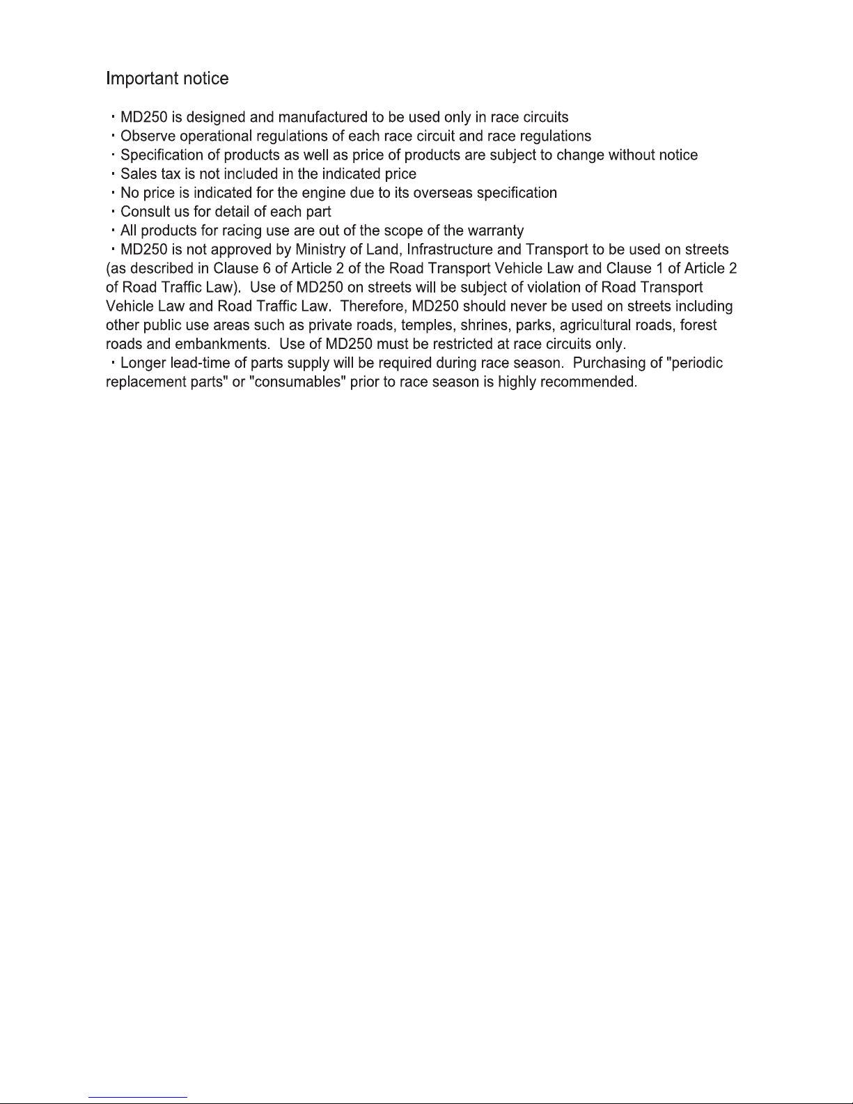
Remove the fuel tank cap.
Fuel tank capacity: 7.0 liter
Fuel: Unleaded high-octane gasoline
Be sure to install the fuel tank cap and breather tube before ride.
Coolant
MD250H uses water for its engine cooling system.
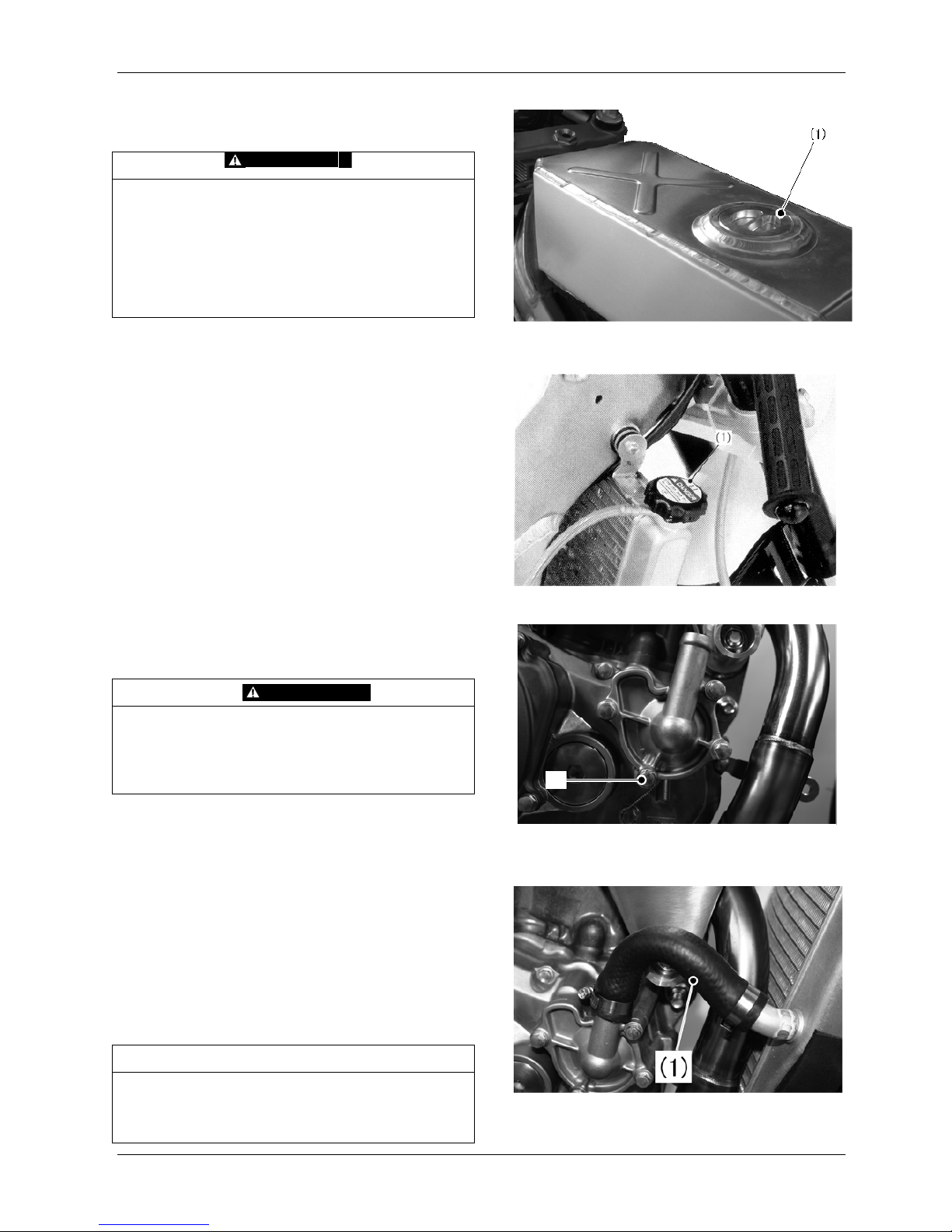
Remove the radiator cap and fill the radiator with coolant water up to
the filler neck.
Coolant: Tap water (soft water) or drinking water
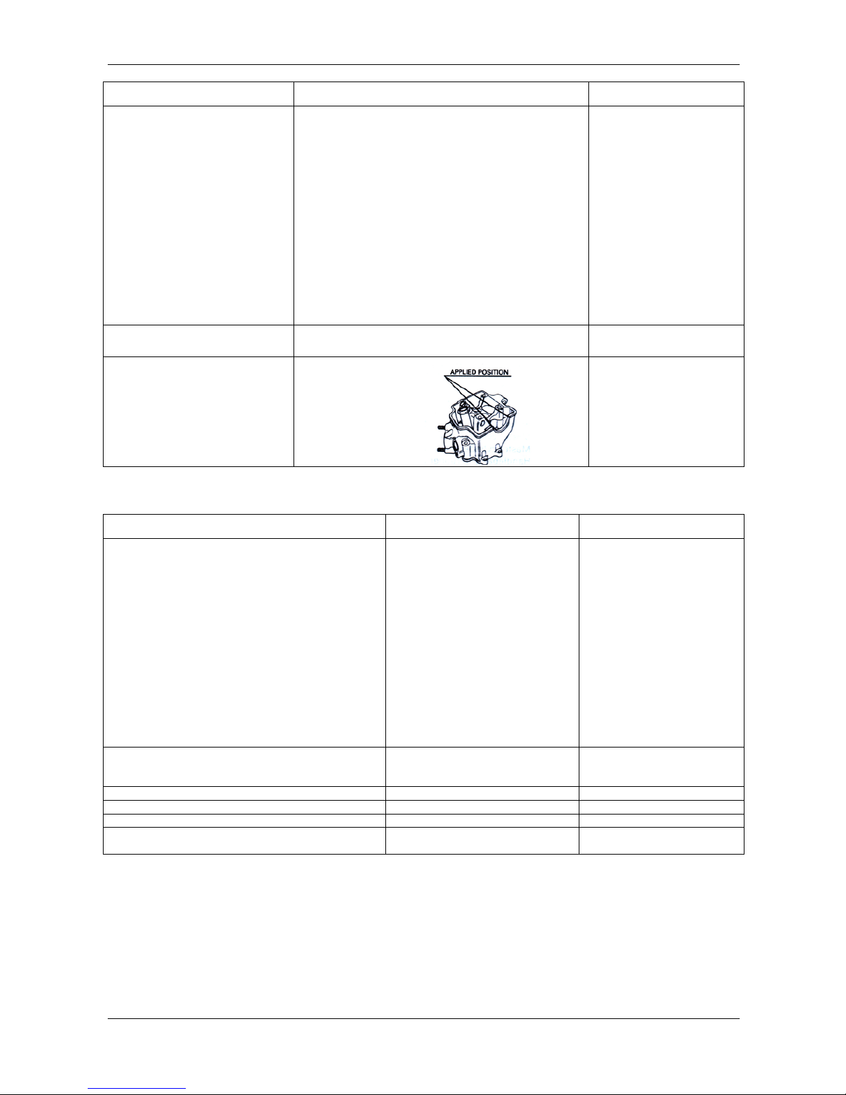
The “DANGER” label on the top of the radiator cap indicates
potential danger.
Be sure to bleed any air trapped in the coolant system after refilling
the coolant. Remaining air may cause the engine over heating.
Air bleeding procedure:
1. Remove the radiator cap and fill the radiator with coolant slowly
up to the filler neck.
2. Loosen the drain bolt and release any trapped air.
3. Hold the handle bars and lean the bike left to right for a few times
to release air. If the coolant level drops, add more coolant.
4. Repeat above procedure until the coolant level doesn’t drop.
5. Reinstall the radiator cap and fasten it securely.
Gasoline is explosive. It can cause you to be burned or
seriously hurt due to explosion.
When you handle gasoline;
・ Engine must be stopped. The work area must be free form
flames, sparks or heat source.
・ Work in a well ventilated area.
・ If you spill gasoline, wipe and remove it immediately.
WARNING
Removing the radiator cap while the engine is hot can allow the
coolant to spray out, seriously scalding you.
Always let the engine and radiator cool down before removing
the radiator cap.
Notice
The radiator cap has a double-lock fasten system.
Be sure to fasten the radiator cap completely, otherwise the system will
not hold the required pressure and cause coolant leakage and serious
troubles.
(1) Fuel tank cap
DENGER
DANGER
(1)
Radiator ca
p
(1)
(1)
Drain bolt
(1)
Radiator hose
GENERAL INFORMATION
(1)
(2)
6. Remove the radiator cap and start the engine when it is cold.
Check the coolant flow at the filler neck (coolant will not flow if
there is trapped air in the system). Stop the engine and re-check
the coolant level. Add more coolant if necessary, then reinstall
the radiator cap.
Drain any coolant in the catch tank before ride.
Drain coolant from the cooling system after finish riding to avoid
troubles in the system such as corrosion or clogging.
Riding
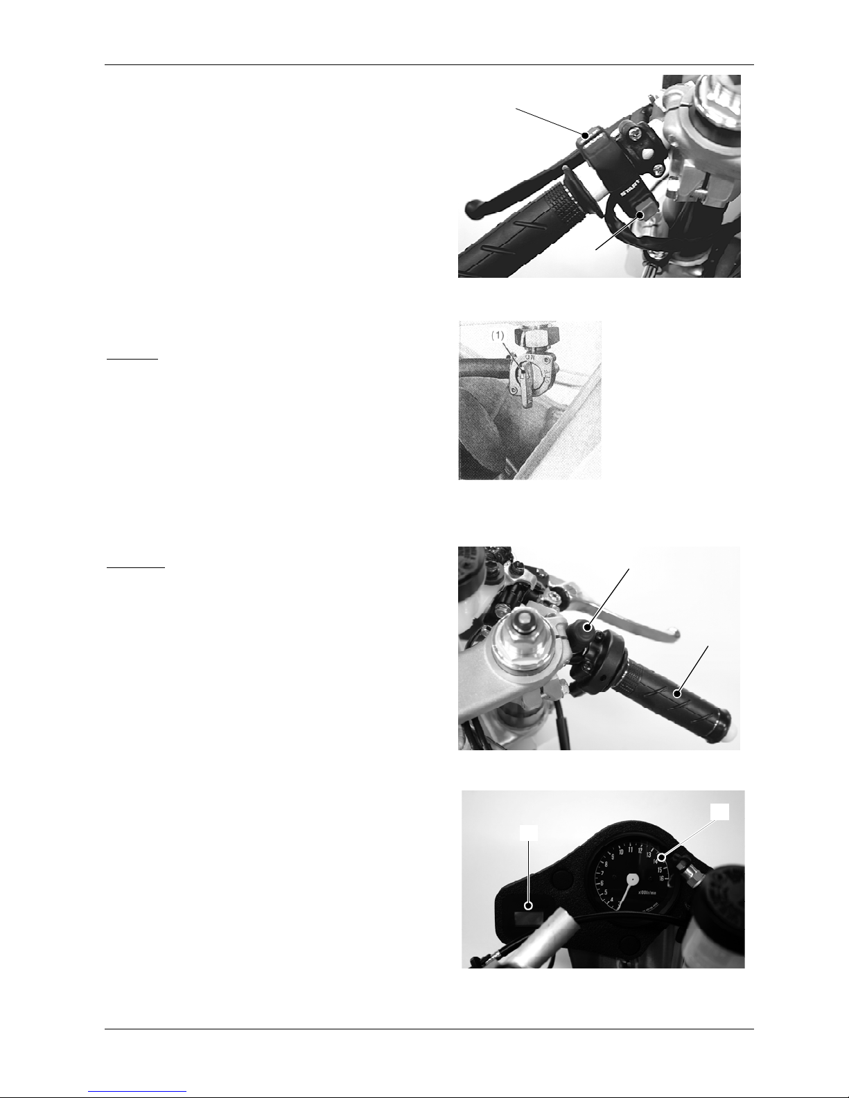
(1)
Main switch (2) Starter button
Starting
Check the coolant level before start the engine. (→1-1)
Cold start:
1. Switch the main switch to “RUN”.
Tachometer and water temp. indicator start operating
(Power ON)
Tachometer: Indicator goes all the way and back to the minimum
value; 3000rpm and the back light turns on.
Water temp. indicator: Start indicating the coolant temperature.
2. Turn the fuel valve to “ON”.
3. Open and close the throttle 2 to 3 times in quick motion.
(1) Fuel valve
4. Push the starter button to start the engine.
(1)
(2)
War m s ta rt :
Follow the “Cold start” procedure above except #3 and start the engine.
Stopping
1. Shift the transmission into neutral.
2. Turn the fuel valve to “OFF”.
3. Push the engine stop button when the engine rev drops and keep
until the engine stops completely.
4. Switch the main switch to “OFF”.
Leaving the fuel valve “ON” may cause starting difficulty especially
when the carburetor overflow the gasoline.
(1) Throttle grip (2) Engine stop button
(1)
(2)
Engine warm up
Do not run the engine at high rev idle for too long during the warming
up.
1. Start the engine, then open the throttle instantaneously while
obtaining 5,000rpm~6,000rpm until the coolant temperature
rises to 40~50℃.
2. Then, open the throttle further in same instantaneous motion up
to 8,000rpm until the temperature rises to 70℃, and stop the
engine.
3. To stop the engine, close the throttle and push the engine stop
button until the engine stops.
(1) Tachometer (2) Water temp indicator
PRINT EDITION 2.1
1-2

GENERAL INFORMATION
PRINT EDITION 2.1
1-3
Break-in ride
First break-in ride
Keep the engine rev constant at the specified rpm during break-in ride. Shift speed up and down below the specified rpm. Use
relatively high gears and observe function of each part. Use 4 to 5 speed gears when riding through straight section of circuit tracks.
Up to 7,000rpm…………… about 50km (approx. 30min)
Up to 8,000rpm‥………… about 15km
Up to 9,000rpm…………… about 15km
Up to 10,000rpm ………… about 15km
Total: approx. 1hr or 95km
After parts change
・ Perform same amount of break-in ride as first break-in when cylinder or crankshaft is replaced: approx. 1hr (95km)
・ In case of replacement of engine parts such as piston, piston rings and gears:
Up to 7,000rpm………… about 20km
Up to8,000rpm………… about 10km
Up to 9,000rpm………… about 10km
Up to 10,000rpm……… about 10km
Total: approx. 30min or 50km
・ Replace the transmission oil(⇒3-6) after break-in rides. Check the contamination and foreign substances in used oil.
GENERAL INFORMATION
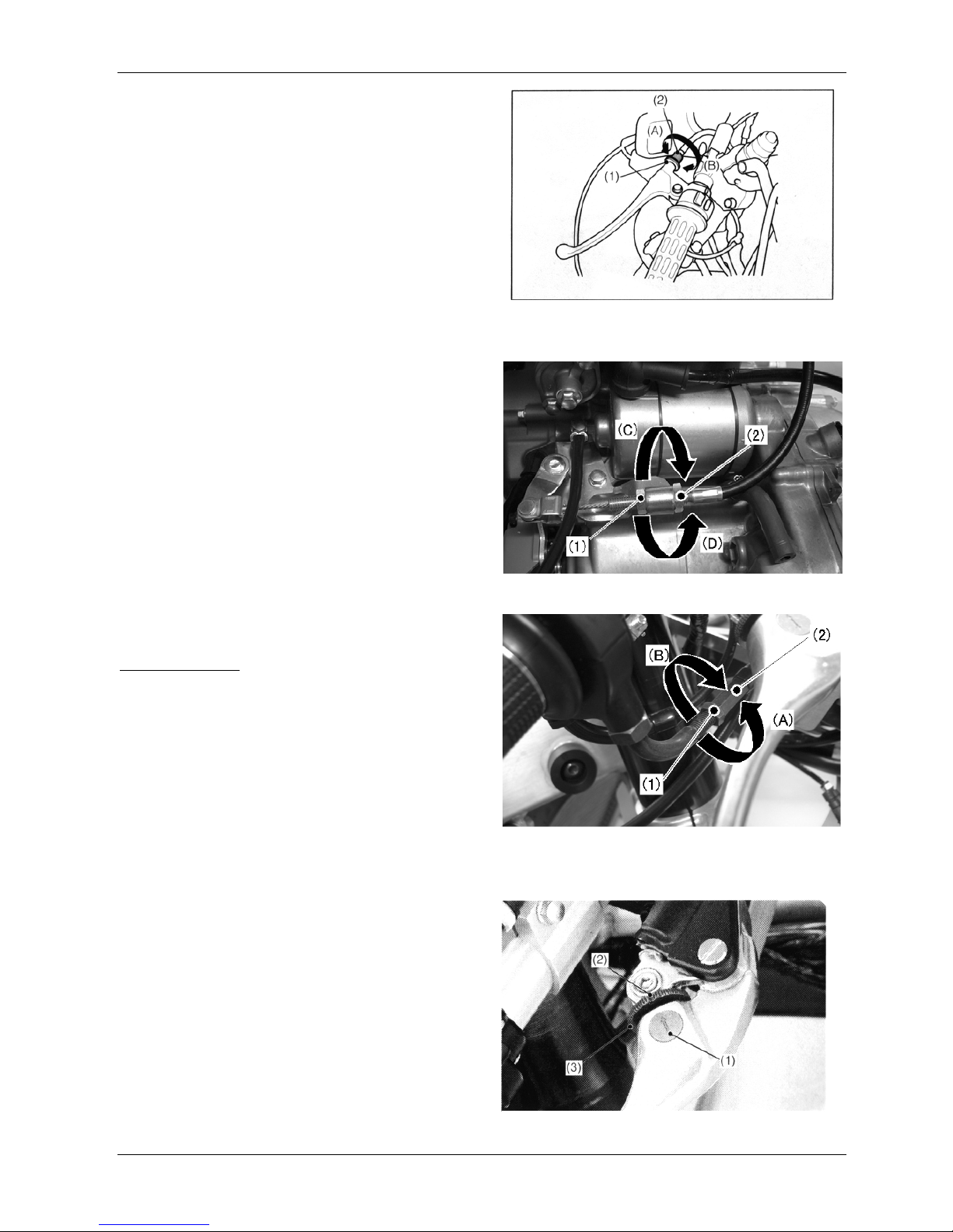
(1) Lock nut (2) Adjuster
(A) Increase the free play (B) Decrease the free play
Operation system
Clutch
Check the clutch lever free play at the lever end.
Free play: 10 – 20mm
Minor adjustments can be made at the cable end adjuster on the
lever.
・ Turning the cable end adjuster in direction A will increase free
play
・ Turning the cable end adjuster in direction B will decrease free
play.
Major adjustments can be made with the in-line cable adjuster
located behind the starter motor.
・ Turning the adjuster in direction C will increase free play
・ Turning the adjuster in direction D will decrease free play
Start the engine and check the clutch for disengaging or slips.
(1) Lock nut (2) Adjuster
(C) Increase the free play (D) Decrease the free play
Throttle grip
Throttle grip free play
Check the free play at the throttle grip flange.
Free play: 3mm
Minor adjustments are made with the throttle grip side adjuster.
・ Turning the adjuster in direction A will increase free play
・ Turning the adjuster in direction B will decrease free play
Tighten the lock nut after adjustment.
Check the throttle grip for its operation.
(1) Lock nut (2) Adjuster
(A) Increase free play (B) Decrease free play
(1)
Arrow mark (2) Alignment mark (3) Adjuste
r
Front brake lever adjustment
The brake lever position can be adjusted by adjuster.
Adjust the brake lever to appropriate position by using the arrow and
alignment marks as reference.
PRINT EDITION 2.1
1-4

GENERAL INFORMATION
Brake pedal height
Adjust the brake pedal to the desired height by loosening the lock nut
and turning the push rod.
Apply grease to the brake pedal axle at every ride.
(1) Lock nut (2) Adjuster
(A) Pedal goes higher (B) Pedal goes lower
Gear shift linkage
(1)
(2)
(1)
The change pedal height can be adjusted by changing the length of the
change rod.
Loosen the lock nuts at both ends and turn the change rod to adjust
the change pedal height. Measure the distance between 2 pillow b
as a reference to the pedal height.
alls
Change rod adjustable length (between the pillow balls)
minimum length: 311mm
maximum length: 332mm
One of 2 ends of the change rod had reverse threads.
Shift pattern: 1 up 4 down
(1)
Lock nut (2) Change rod
1 UP 4 DOWN
(1) Change arm (2) Change rod
(3) Change pedal
PRINT EDITION 2.1
1-5
GENERAL INFORMATION
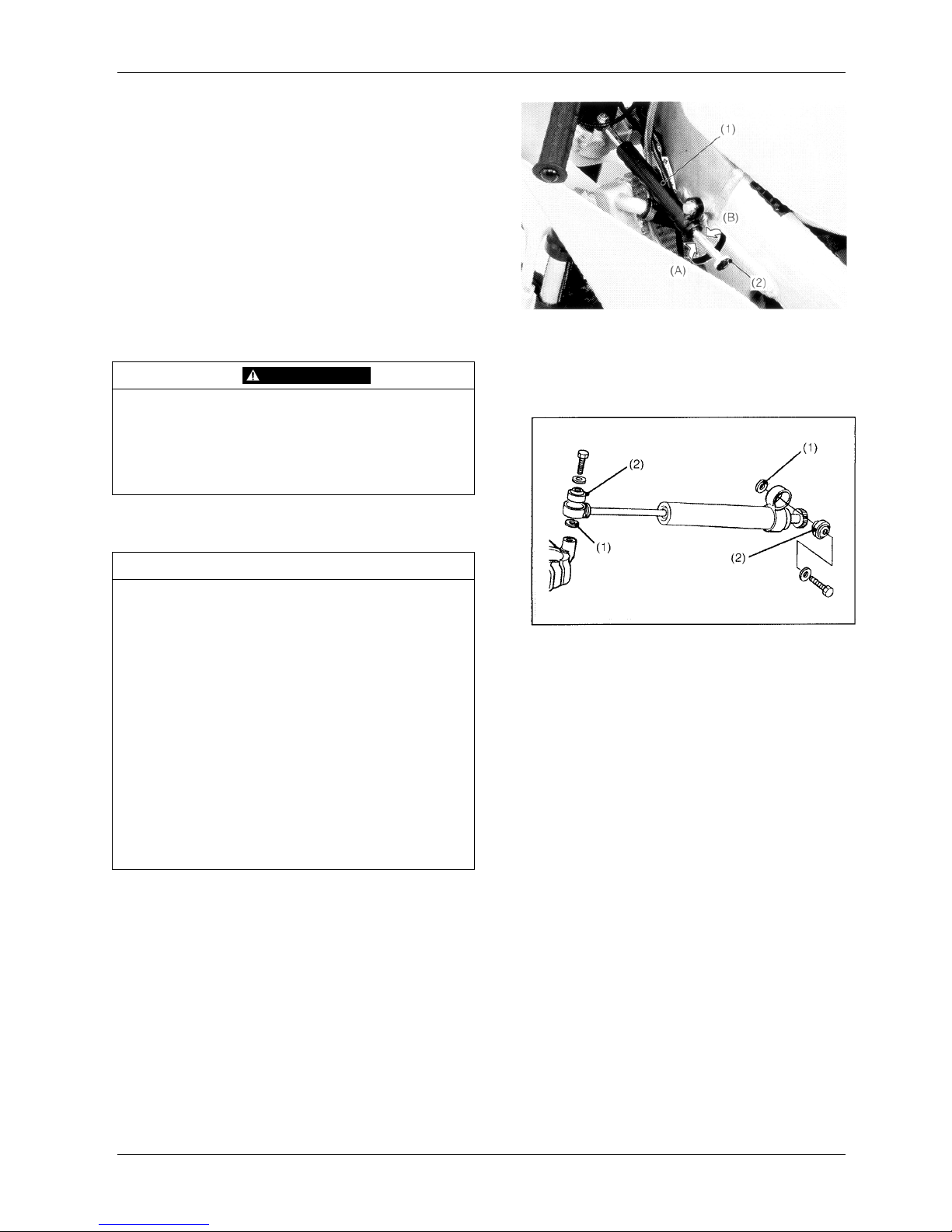
Steering damper
The steering damper damping force can be adjusted by its adjuster.
The damping force is adjusted in 7steps. The damping force increases
as turning the adjuster clockwise and obtain the maximum damping
force at the turning end.
The damping force decrease as turning the adjuster counter-clockwise.
Standard setting: Minimum damping force
(1) Steering damper (2) Adjuster
(A) Increase damping force (B) Decrease damping force
CAUTION
Do not start the steering damper setting from its maximum
damping force position. It will cause problem in handling of the
motorcycle.
Always start the steering damper setting from its minimum
damping force position.
Note
・Do not turn the adjuster to clockwise further than its turning
end. It will break the stopper in the steering damper and
cause damping force adjustment malfunction.
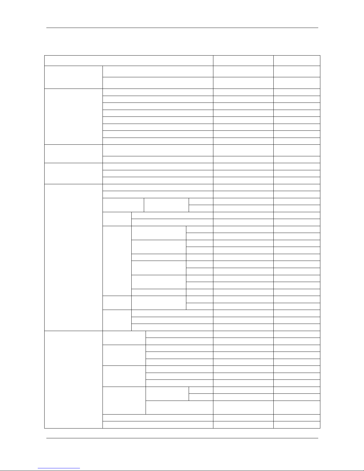
・Be sure to install the steering damper within the tolerance of 2
spherical bearings movement. Inappropriate installation will
create unnecessary stress on the piston rod and disturb
steering movement.
・Do not damage the sliding surface of the piston rod. Score
marks or hitting marks cause damper oil leaks.
・Make sure that the steering damper is not fully stretched at
both steering ends. Also check the steering damper for
interference with the frame or other parts of the motorcycle.
・Do not disassemble the steering damper unit
・Make sure to use the thick washers (2.3mm) between the frame
and spherical bearing, and bottom bridge and spherical
bearing, then tighten the bolts.
(1)
Washers(2.3mm) (2) Spherical bearings
PRINT EDITION 2.1
1-6
SERVICE INFORMATION
Service specification
Unit: mm
ITEM STANDARD SERVICE LIMIT
Recommended transmission oil
HONDA Ultra-G1 (4-stroke
motorcycle oil)
LUBRICATION
SYSTEM
SPECIFICATIONS
Recommended engine oil
HONDA Ultra-G1 (4-stroke
motorcycle oil)
Venturi diameter 40
Carburetor identification number FCR12C A
Float level 6.0
Main jet #160
Slow jet #42
Jet needle NCYR
Pilot screw initial opening 1-1/4 turns out
FUEL SYSEM
SPECIFICATIONS
Jet needle clip position(Standard)
4th groove from top
Coolant
Tap water (soft water) or
drinking water
COOLING SYSEM
SPECIFICATIONS
Radiator cap relief pressure
1.1-1.4kgf/c ㎡
Clutch spring free length 38.8 38.0
Clutch disc thickness 2.92-3.08 2.85
CLUTCH
SPECIFICATION
Clutch plate warpage
- 0.10
Cylinder compression 392kPa(0.95-1.25kgf/c ㎡) -
Cylinder head warpage - 0.05
IN 35.580-35.660 35.44 Camshaft Cam lobe height
EX 25.081-25.161 24.98
Valve lifter O.D. 22.478-22.493 22.47 Valve lifter
Valve lifter bore I.D. 22.510-22.526 22.54
IN 0.12±0.3 - Valve clearance
EX 0.28±0.3 -
IN 4.975-4.990 - Valve stem O.D.
EX 4.965-4.980 4.955
Valve guide I.D. IN/EX 5.000-5.012 5.052
IN 0.010-0.037 - Stem-to-guide
clearance
EX 0.020-0.047 -
IN 14.8-15.0 - Valve guide projection
above cylinder head
EX 19.9-20.1 -
Valve and
valve guide
Valve sea t w idth IN/EX 0.90-1.10 1.7
IN 39.47 38.5 Valv e
spring
Valve spring free
length
EX 43.07 42.1
Rocker arm I.D. 12.016-12.034 12.07
Rocker arm shaft O.D. 11.977-11.985 11. 93
CYLINDER
HEAD/VALVE
SPECIFICATION
Rocker
arm
Rocker arm-to-shaft clearance 0.031-0.057 0.11
War pa ge - 0.05 Cylinder
I.D. 78.00-78.015 78.025
Circularity / Cylindricity - 0.010
O.D. (7mm from the bottom of skirt) 77.970-77.980 77.940
Piston
Cylinder-to-piston clearance 0.020-0.045 0.085
Piston pin bore I.D. 16.002-16.008 16.03
Piston pin O.D. 15.994-16.000 15.98
Piston pin
Piston-to-piston pin clearance 0.002-0.014 0.04
Top ring 0.15-0.25 0.39 Piston ring end
gap
Oil ring 0.20-0.70 0.90
Piston ring
Piston ring-to ring groove
clearance (Top)
0.065-0.100 0.08
Connecting rod small end I.D. 16.016-16.038 16.04
CYLINDER/PISTON
SPECIFICATIONS
Connecting rod-to-piston pin clearance 0.016-0.044 0.06
PRINT EDITION 2.1
2-1

SERVICE INFORMATION
ITEM STANDARD SERVICE LIMIT
FRONT 1.8kgf/c ㎡ - Cold tire pressure
REAR
1.9kgf/c ㎡ -
Axle runout - 0.5mm
Radical - 0.3mm Wheel rim runout
Axial - 0.3mm
Drive chain slack 20mm±2mm -
WHEEL/TIRE
SPECIFICATION
Drive chain slider thickness
- 2.0mm
Fork tube runout - 0.20mm
Fork oil (type) HONDA Ultra Cushion Oil
Special (SAE5W), SHOWA
SS05 or equivalent
-
R L
(Std) 111mm 106mm -
(Upper) 92mm 87mm -
Fork oil level
(Lower) 152mm
147mm -
(Std) 233c㎥ -
(Upper) 257c㎥ -
Fluid capacity
(Lower) 210c㎥ -
Compression damping adjuster standard position 10 clicks out from full in -
FRONT
SUSPENSION
SPECIFICATION
Rebound damping adjuster standard position
6 clicks out from full in -
Damper gas pressure 10.0-13.0kgf/c ㎡ -
Damper rod compressed force (at 10mm compressed) 15.4-20.0kgf -
Spring installed length 147mm -
Compression damping adjuster standard position 6 clicks out from full in -
REAR
SUSPENSION
SPECIFICATION
Rebound damping adjuster standard position 10 clicks out from full in -
Brake fluid DOT4 -
Brake disk thickness 4.0mm 3.5mm
Brake disc runout - 0.3mm
Master cylinder I.D. 12.700-12.743mm 12.755mm
Front
Master piston O.D. 12.657-12.684mm 12.650mm
Brake disk thickness 4.0mm 3.5mm
Brake disc runout - 0.3mm
Master cylinder I.D. 12.700-12.743mm 12.755mm
Master piston O.D. 12.657-12.684mm 12.650mm
Caliper cylinder I.D. 27.000-27.005mm 27.06mm
HYDRAULIC
BRAKE
SPECIFICATION
Rear
Caliper piston I.D. 26.900-26.950mm 26.85mm
PRINT EDITION 2.1
2-2
SERVICE INFORMATION
Tightening torque values
Engine
ITEM
THREAD
DIA.(mm) QTY
TORQUE
N・m(kgf・m)
REMARKS
Engine oil drain bolt
Transmission oil drain bolt
Timing hole cap
Crankshaft hole cap
Rocker arm shaft cap
Spark plug
Throttle drum cover bolt
Needle jet
Main jet
Slow jet
Starter jet
Leak jet
Maintenance cover bolt
Carburetor top cover bolt
Throttle shaft screw
Float chamber screw
Diaphragm cover screw
Carburetor drain plug
SE valve lock nut
Hot start cable nut
Needle holder
Throttle position sensor mount torx screw
Water pump impeller
Cylinder head cover bolt
Camshaft holder bolt
Cylinder head nut
Cam chain tensioner bolt
Decompressor cam stopper bolt
Shift drum center bolt
Shift drum stopper arm bolt
Clutch center lock nut
Clutch spring bolt
Gear shift return spring pin
Crankshaft bearing set plate torx screw
Countershaft bearing set plate screw
Mainshaft bearing set plate bolt
Shift drum bearing set plate bolt
Drive sprocket bolt
Primary drive gear bolt
Balancer shaft nut
Oil jet mounting bolt
Flywheel nut
Pulse generator mounting bolt
Stator mounting screw
Clutch cover bolt
8
8
14
30
14
10
5
7
5
6
5
4
4
4
4
4
4
18
12
-
8
5
7
6
7
9
6
5
8
6
18
6
8
6
6
6
6
8
12
14
6
12
5
4
6
1
1
1
1
1
1
1
1
1
1
1
1
2
2
1
4
3
1
1
1
1
1
1
2
4
4
1
1
1
1
1
5
1
2
2
2
2
1
1
1
1
1
2
3
5
16 (1.6)
16 (1.6)
6.0 (0.6)
15 (1.5)
6.0 (0.6)
16 (1.6)
3.4 (0.3)
1.8 (0.2)
1.5 (0.2)
1.5 (0.2)
1.5 (0.2)
0.3 (0.03)
2.1 (0.2)
2.1 (0.2)
2.1 (0.2)
2.1 (0.2)
2.1 (0.2)
4.9 (0.5)
2.1 (0.2)
2.1 (0.2)
2.1 (0.2)
3.9 (0.4)
12 (1.2)
10 (1.0)
16 (1.6)
39 (4.0)
12 (1.2)
10 (1.0)
22 (2.2)
12 (1.2)
69 (7.0)
12 (1.2)
22 (2.2)
20 (2.0)
10 (1.0)
10 (1.0)
10 (1.0)
31 (3.2)
108 (11.0)
44 (4.5)
10 (1.0)
64 (6.5)
5.2 (0.5)
2.6 (0.3)
10 (1.0)
Apply engine oil
Apply engine oil
Apply grease
Apply grease
Apply locking agent
Apply locking agent
Reverse thread
Apply engine oil
Apply engine oil
Apply locking agent
Apply locking agent
Apply locking agent
(TB1373N or equivalent)
Apply locking agent
Apply locking agent
Apply locking agent
Apply engine oil
Apply locking agent
Apply engine oil
Apply locking agent
Apply locking agent
PRINT EDITION 2.1
2-3

SERVICE INFORMATION
FRAME
ITEM
THREAD
DIA.(mm) QTY
TORQUE
N・m(kgf・m)
REMARKS
Engine mounting bolt (1 crankcase bolt)
Steering thread
Steering stem bolt
Top / bottom bridge pinch bolt
Axle nut
Axle holder bolt
Fork bolt
Fork damper rod lock nut
Fork socket bolt
Swingarm pivot adjusting bolt
Swingarm pivot adjusting bolt lock nut
Swingarm pivot nut
Chain guard bolt
Rear cushion spring lock nut
Upper joint lock nut
Front brake caliper mounting bolt
Rear caliper pad pin
Rear caliper pad pin plug
Front brake hose oil bolt
Rear brake hose oil bolt
Front brake bleeder bolt
Front caliper bleeder screw
Brake bleeder screw
Front brake disc bolt
Rear brake disc bolt
Torque rod end nut
Fuel valve lock nut
Handle holder pinch bolt
Clutch cable nut
Clutch lever holder screw
Step holder socket bolt
Tw s ensor
10
26
18
8
14
8
39
20
10
30
30
18
6
50
16
10
10
10
10
10
8
10
8
6
8
8
18
8
8
5
8
12
3
1
1
6
2
4
2
2
2
1
1
1
2
1
1
2
2
2
2
2
3
1
1
6
3
2
12
1
1
2
4
1
41.2(4.2)
6(0.6)
59(6.0)
23(2.3)
69(7.0)
22(2.2)
34(3.5)
34(3.5)
34(3.5)
15(1.5)
44(4.5)
95(9.7)
8(0.8)
49(5.0)
64(6.5)
49(5.0)
18(1.8)
1(0.15)
24(2.4)
24(2.4)
24(2,4)
7(0.7)
7(0.7)
12(1.2)
42(4.3)
18(1.8)
19(1.9)
23(2.3)
10(1.O)
4(0.40)
15(1.5)
11(1.1)
Apply grease
Apply oil
Apply grease
Apply grease
Apply grease
Apply grease
Apply grease
Apply grease
・Do not apply oil or grease to fasteners unless otherwise specified in the table.
STANDARD TORQUE VALUES
FASTENER TYPE
TORQUE
N・m(kgf・m)
5mm bolt and nut
6mm bolt, SH flange bolt and nut
8mm bolt and nut
10mm bolt and nut
12mm bolt and nut
5mm screw
6mm screw
6mm flange bolt (NSHF type) and nut
8mm flange bolt and nut
10mm flange bolt and nut
5 (0.5)
10 (1.0)
22 (2.2)
34 (3.5)
54 (5.5)
4 (0.40)
9 (0.9)
12 (1.2)
26 (2.7)
39 (4.0)
PRINT EDITION 2.1
2-4
SERVICE INFORMATION
LUBRICATION & SEAL POINTS
ENGINE
ITEM LOCATION MATERIAL
Camshaft
Rocker arm
Valve stem
Valve lifter
Crankshaft
Clutch outer guide
Clutch lifter lever
Connecting rod
Mainshaft
Countershaft
Shift fork
Shift fork shaft
Each gears
Cam lobe, journal
Shaft, slipper surface
Valve guide sliding surface, stem end
Outer surface
Big end, small end
Sliding surface
Cam area
Small end inner surface
Spline area, sliding surface
Spline area, sliding surface
Claw, guide pin, sliding surface
Outer surface
Groove
Molybdenum oil solution
(mixture of the engine oil and
molybdenum grease with the ratio
1:1)
Engine oil drain bolt
Transmission oil drain bolt
Camshaft holder bolt
Crankshaft
Cylinder
Cylinder head nut
Decompressor cam
Balancer shaft nut
Piston
Piston pin
Piston ring
Clutch outer
Clutch lifter
Clutch disc / plate
Clutch center lock nut
Primary drive gear bolt
Flywheel nut
Shift drum
Shift spindle
Oil pump rotor
Seal ring
Each bearings
Each O-rings
Threads
Threads
Threads
Oil seal outer surface
Bore
Threads, seating surface
Sliding area
Threads, seating surface
Outer surface, pin hole
Outer surface
Whole surface
Sliding area
Needle bearing contact area
Lining surface
Threads, seating surface
Threads, seating surface
Threads, seating surface
Guide groove
Serration area
Sliding area
Whole surface
Rolling contact area
Whole surface
Engine oil
Crankshaft hole cap
Timing hole cap
Rocker arm shaft cap
Camshaft set ring
Oil filter spring
Dust seal
Wat er se al
Oil seals
Threads
Threads
Threads
Whole surface
Contact area
Lips
Lips
Lips
Multi-purpose grease
PRINT EDITION 2.1
2-5
SERVICE INFORMATION
ITEM LOCATION MATERIAL
Shift drum center bolt
Stator screw
Pulse generator bolt
Mainshaft bearing set plate bolt
Countershaft bearing set plate screw
Shift drum bearing set plate bolt
Oil jet mounting bolt
Breather plate bolt
Cam chain tensioner pivot bolt
Throttle shaft screw
Throttle position sensor torx bolt
Brake pedal pivot bolt
Decompressor cam stopper plate bolt
Oil guard plate bolt
Threads(Coating width: 6.5±1mm/ from 1~2mm off tip)
Threads(Coating width: 3.0±1mm)
Threads(Coating width: 4.5±1mm)
Threads
Threads(Coating width: 3.5±1mm)
Threads
Threads(Coating width: 6.5±1mm/ from 1~2mm off tip)
Threads(Coating width: 6.5±1mm/ from 1~2mm off tip)
Threads(Coating width:6.5±1mm/ from 1~2mm off tip)
Threads
Threads
Threads
Threads(Coating width: 6.5±1mm/ from 1~2mm off tip)
Threads
Locking agent
Crankshaft bearing set plate torx screw Threads(Coating width: 6.5±1mm) High strength locking agent
(TB1373N or equivalent)
AC generator wire grommet
Cylinder head
Seating surface
Semi-circular portion
Liquid sealant
FRAME
LOCATION MATERIAL REMARKS
Handle lever pivot bolt sliding area
Cable adjuster bolt threads
Axle shaft outer surface
Driven sprocket washer seating surfaces
Driven sprocket collar O-ring
Steering head bearing / race
Steering stem bolt threads / seating area
Caliper bracket both surfaces
Brake pedal pivot sliding area
Shift pedal pivot sliding area
Swingarm pivot ball bearing / needle bearing
Swingarm pivot dust seal lip
Swingarm pivot adjuster bolt threads / seating area
Cushion arm needle bearing
Cushion arm dust seal lip
Tw sensor threads
Multi-purpose grease
Master cylinder pivot sliding area / piston contact area
Rear brake caliper pin bolt
Rear brake caliper piston seal
Silicone grease
Silencer joint area Heat resistant sealing agent (ME30) MORIWAKI
Drive chain slider screw threads Locking agent
Steering thread Honda Ultra U
Handle grip / Throttle pipe Honda Bond A The material must not come
out more than 3mm
※Heat resistant sealing agent (ME30) Part number: 860-806-0600
PRINT EDITION 2.1
2-6

MAINTENANCE
PRINT EDITION 2.1
3-1
・Fuel leak, oil leak and coolant leak
・ Coolant level
・ Engine oil level
・ Transmission oil level
・Spark plug burning condition, coloration, tightening, cap loose
・Clutch lever play, clutch operation
・Throttle grip free play, throttle valve operation
・Steering head operation, loose, deformation or damages
・Frame damages, cracks
・Tire pressure, wear
・Front and rear suspension operation, oil leak
・Brake lever and pedal free play, brake performance, fluid level
・Drive chain slack, lubrication
・Drive chain slider damage, wear
・Exhaust spring fatigue, damage
・Nuts, bolts, fasteners tightening, loose (oil drain bolt wire-lock, specially)ock, specially)
Pre-ride inspection
Perform maintenance operation according to following chart to obtain performance of your MD250H. The maintenance
schedule may differ depending on condition of use. Machines subjected to severe use require more frequent servicing.
I: Inspect and Clean, Adjust, Lubricate or Replace if necessary. C: Clean. L: Lubricate
MAINTENANCE SCHEDULE
ITEMS
FREQUENC
Y
Inspection Replace Note
Throttle operation I
Carburetor box C
Breather tube I Bend, Break
Cooling system I
Engine oil I 500 km
Engine oil filter I 1,000 km
Transmission oil I 500 km Replace every after wet race
Camshaft 1,000 km 4,000 km Score, wear
Valve, Intake 1,000 km 2,000 km Bend, seat damage, Do not lap the intake valve
Valve, Exhaust 1,000 km 4,000 km Bend, seat damage
Cylinder head 1,000 km 4,000 km Valve seat face damage
Valve spring 1,000 km 2,000 km Break, Valve spring fa tigue
Piston 1,000 km 2,000 km Score, wear, Replace in case of a collision with valves
Piston rings 1,000 km 2,000 km Score, wear
Crankshaft 2,000 km 4,000 km Runout check, Service limit: L 0.05, R 0.03
Clutch I Every race Clutch spring fatigue
Spark plug 1,000 km 2,000 km
Drive chain I・L
Drive chain slider I
Drive / Driven sprocket I
Brake fluid I Replace every 3 races (Replace every after wet race)
Brake syste m I
Control cables I・LClutch, Axel
Exhaust silencer I
Suspension I
Overhaul operation is recommended after every
2,000km or every 4 races
Swingarm / Cushion linkage C
Fork oil I
Replace after the first 100km, then replace after every
3 races
Wheels / Tires I
Nuts, Bolts, Fasteners I
WARNING
Improper inspection or maintenance service can be a
cause of unpredictable troubles or serious accidents.
・Be sure to perform inspection and maintenance
service correctly
・Perform Pre-ride inspection before use
・All defectives or abnormalities must be repaired
before use

MAINTENANCE
During engine warm-up
・Thermometer, rev counter operation
・Fuel leak, oil leak and coolant leak
During running
・Thermometer, tachometer indicating value
・Carburetor setting
・Gear ratio setting
・Control system (shift pedal, throttle or others) operation
・Brake performance
Post-ride inspection
・Fuel leak, oil leak and coolant leak
・Nuts, bolts, fasteners tightening, loose or fall
Note
Periodic replacement parts and consumables must be
checked every after riding and replaced if necessary.
・Parts replacement schedule is based upon sprint race conditions and therefore, it is reference for your use. Machines subjected to severe use
require more frequent replacement operation. MORIWAKI ENGINERRING is not responsible for lifetime of any periodic replacement
parts or consumables.
ITEMS REMARK
Engine
Clutch disc, plates
Clutch springs
Drive sprocket
Spark plug
Thickness, discoloring, wear
Fatigue
Wear, damage
Wear on electrode, gap, insulator damage
Frame
Tires
Brake pads
Drive chain slider
Driven sprocket
Exhaust spring
Silencer glass wool
Wear
Wear
Wear
Wear, damage
Fatigue, damage
Exhaust noise increase
PRINT EDITION 2.1
3-2
MAINTENANCE
Engine oil / Oil filter
Oil level inspection
CAUTION
・Support the machine upright on a level surface when you
perform oil level inspection or adding oil.
・Be aware that the engine and the transmission have
individual lubrication systems.
Start the engine and let it idle for 3 minutes.
Stop the engine and wait 3 minutes.
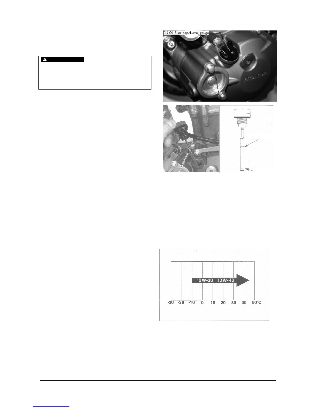
Remove the oil filler cap / level gauge and wipe the oil with a
clean cloth.
Insert the level gauge without screwing it in, remove it and
check the oil level.
Oil level must be within upper and lower level lines.
Lower level line
(1) Oil filler cap / Level gauge
Upper level line
If the oil level is below or near the lower level line on the
level gauge, add the recommended engine oil to the upper
level line
SUGGESTED OIL:
・Honda Ultra G1 (4-stroke motorcycle oil)
SAE10W-30
Or an equivalent oil with following specifications.
・API classification: SG, SH or SJ
・JASO standard: MA
・SAE viscosity: Refer to the chart
Oils with API classification specified above may not be
suitable to your machine due to slight difference in
characteristics.
PRINT EDITION 2.1
3-3
MAINTENANCE
PRINT EDITION 2.1
3-4
Engine oil / Oil filter change
Note
It is easier to drain the engine oil when it is warm.
Start the engine and let it idle for 3 minutes. Stop the
engine and support the machine upright on a level surface.
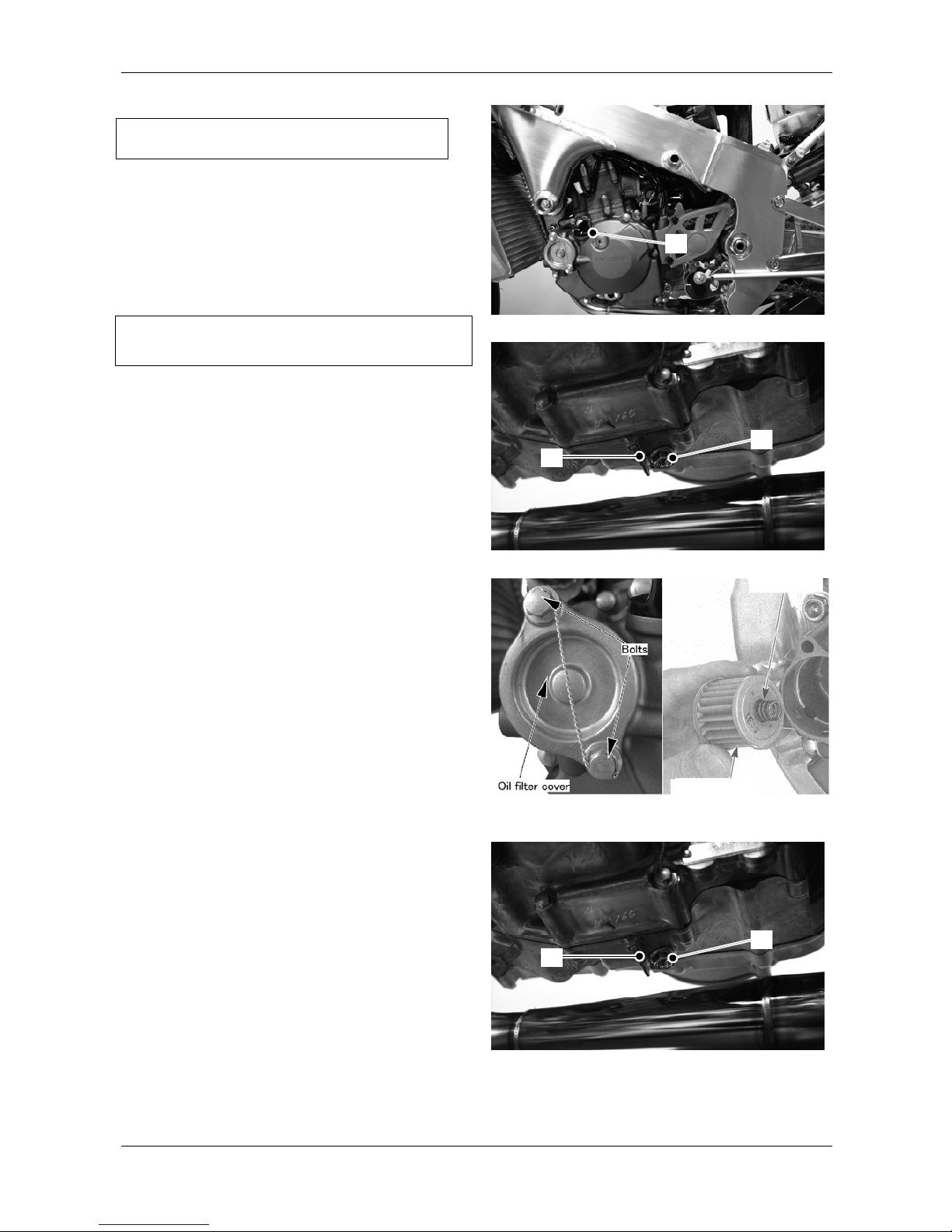
Remove the oil filler cap / level gauge.
Remove the bolts and oil filter cover.
Remove the oil filter and spring.
Install the engine oil drain bolt with a new sealing washer after
engine oil completely drains.
Tighten the drain bolt to the specified torque.
Torque: 1 6N ・m (1.6 kgf・m)
Wire-lock the drain bolt with the engine case.
Remove the engine oil drain bolt and sealing washer, and drain the
engine oil.
Note
Operate the starter motor for a few seconds while pushing the
engine stop button, so the engine oil completely drains.
(1)
(1)
(2)
(1)
Drain bolt / Sealing washer (2) Wire-lock
(1) Oil filler cap / Level gauge
Oil filter
Spring
(1)
Drain bolt / Sealing washer (2) Wire-lock
(1)
(2)
MAINTENANCE
PRINT EDITION 2.1
3-5
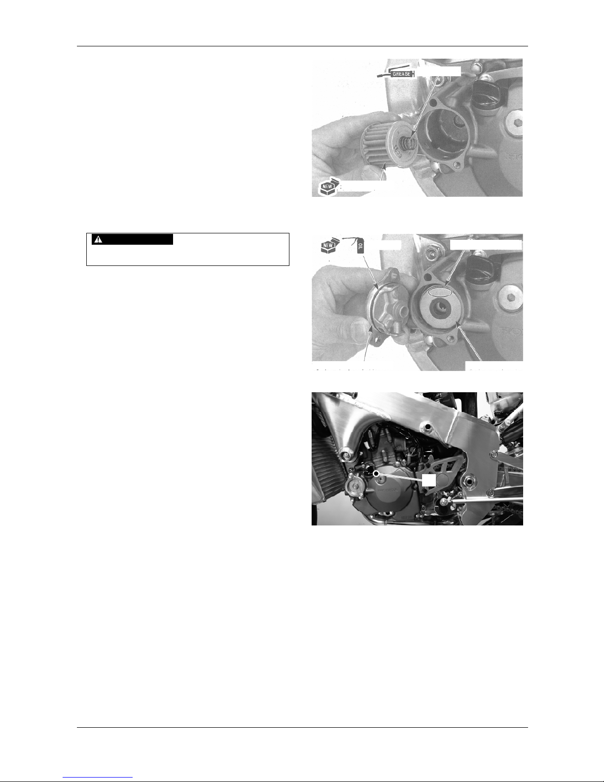
A
pply grease to the filter side of the spring end, then install the
spring into the new oil filter.
Install the oil filter assembly.
CAUTION
Be sure to install the oil filter with the “OUTSIDE”
mark facing out
A
pply engine oil to a new O-ring and install it to the oil filter
cover.
Install the oil filter cover and tighten the bolts securely.
Torque: 1 0N ・m (1.0 kgf・m)
Wirelock the bolts to each other.
Fill the engine with the recommended oil.
Oil capacity:
0.66 liter (at draining)
0.69 liter (at oil filter change)
0.85 liter (at engine disassemble)
Install the oil filler cap / level gauge and tighten it securely.
Start the engine and make sure there are no oil leaks.
Stop the engine and check the oil level.
Wirelock the bolts to each other.
(1)
(1) フィラキャップ/レベルゲージ
Oil filter
Spring
“OUT SIDE” mark
O-rin
g
Oil filter cove
r
Oil filte
r
(1) Oil filler cap / Level gauge
MAINTENANCE
CAUTION
・Support the machine upright on a level surface when you
perform oil level inspection or adding oil.
・Be aware that the transmission and engine have
individual lubrication systems.
Start the engine and let it idle for 3 minutes.
Stop the engine and wait 3 minutes.
Support the motorcycle upright on a level surface, and remove
the oil filler cap, oil check bolt and sealing washer. A small
amount of oil should flow out of the check bolt hole. If a large
amount of oil come out from the hole, let it drain until stops.
If no oil flows out of the check bolt hole, add oil slowly through
the oil filler hole until oil starts to flow out of the check bolt
hole. Install the oil filler cap and oil check bolt with a new
sealing washer, then restart the engine and repeat the
procedures above.
CAUTION
After checking the oil level or adding oil, tighten the oil
check bolt and oil filler cap securely. And make sure
there are no oil leaks.
Transmission oil change
Note
Warm-up the engine before draining the oil. Support the
motorcycle upright on a level surface to drain the oil.
Remove the oil filler cap from the right crankcase cover and
the oil drain bolt from the left crankcase to drain oil.
A
fter the oil has drained completely, apply transmission oil
to the drain bolt threads and install the drain bolt with a
new sealing washer. Tighten the transmission oil drain bolt
to the specified torque.
Torque: 16 N・m (1.6 kgf・m)
A
dd the recommended transmission oil.
Recommended transmission oil:
・Honda Ultra G1 (4-stroke motorcycle oil)
SAE10W-30
Or an equivalent oil with following specifications.
(1)
(1) Oil check bolt / Sealing washer
(1)
(1) Drain bolt / Sealing washer
Wir-lock the oil filler cap.
・API classification: SG, SH or SJ
・JASO standard: MA
Oils with API classification specified above may not be suitable
to your machine due to slight difference in characteristics.
Transmission oil
Transmission oil level inspection
(1)
(1) Oil filler cap
Transmission oil capacity: 0.67 liter (at draining)
: 0.75 liter (at disassembly)
Check the oil level after performing the oil change operation.
Wire-lock the transmission oil drain bolt.
PRINT EDITION 2.1
3-6
MAINTENANCE
PRINT EDITION 2.1
3-7
A
fter the oil has drained completely, tighten the drain bolt
securely and wire-lock it.
(1) Overflow tube
Cooling system
Cooling system inspection
1. Check on coolant leak
2. Inspect the radiator houses for cracks or deterioration, or
loose of bands
3. Inspect the radiator installation
4. Check the overflow tube for its installation status and
clogging.
5. Check the radiator air passages for clogging.
6. Inspect the telltale hole for signs of coolant leakage
- If there is coolant leakage, the water pump sealing is
defective and it must be replaced.
- If there is oil leakage, the oil seal is defective and it
must be replaced.
WARNING
Removing the radiator cap while the engine is hot can
allow the coolant to spray out, seriously scalding you.
Always let the engine and radiator cool down before
removing the radiator cap.
(1) Telltale hole
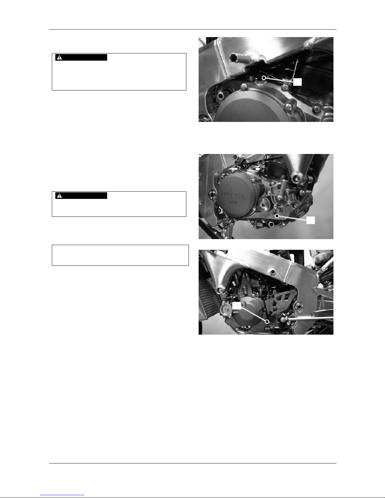
(1)
Oil catch tank is build-in to the left hand side of the main
frame.
Insert the breather tube of the crankcase to the carburetor
box attachment.
Remove the drain bolt to drain any oil left in the oil catch
tank before ride.
Oil catch tank
(1) Drain bolt
(1)
(1)
MAINTENANCE
PRINT EDITION 2.1
3-8
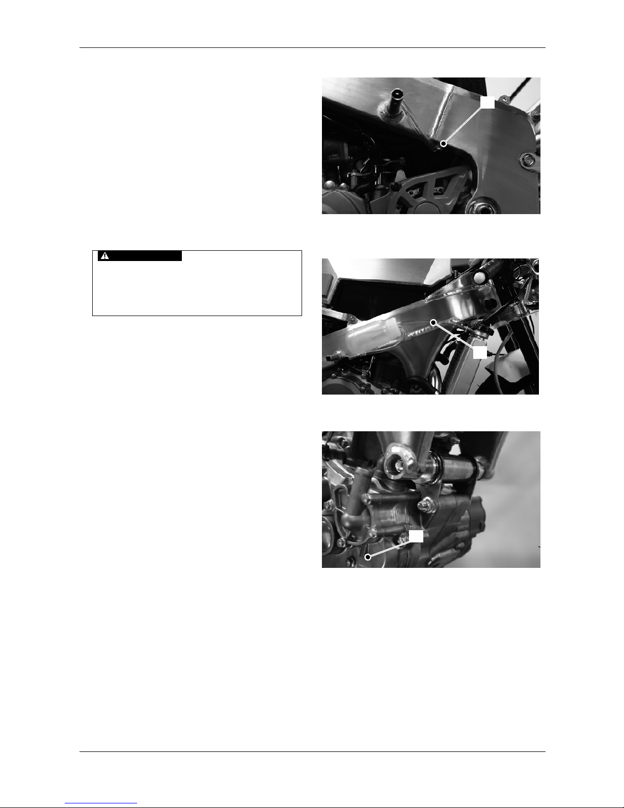
(1) Overflow tube
(2) Overflow catch tank
Coolant overflow catch tank is attached on right hand side
of the main frame with tei-wraps.
Make sure to put an end of the overflow tube into the catch
tank.
Drain any coolant in the catch tank by taking it off from
the frame before ride.
Coolant overflow catch tank
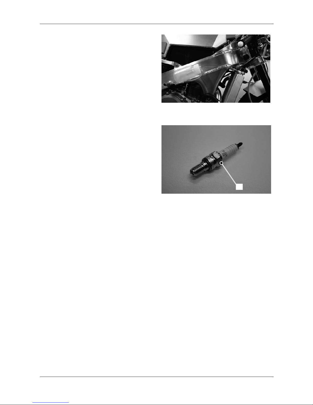
(1) Spark plug
Spark plug
Recommended spark plug
NGK: R0409B-10 (Standard)
A
lways use spark plug with correct thermal value.
Remove the spark plug and measure its gap.
Standard: 0.6―0.7mm
If the spark plug gap is out of specification, replace the plug
with a new one.
In case a spark plug with incorrect thermal value is used, it
may cause engine malfunctions.
Spark plug gap
(1)
MAINTENANCE
PRINT EDITION 2.1
3-9
Fuel tank / Fuel strainer
Check the fuel tube for bend or crack.
Make sure there is no gasoline leaks.
Gasoline is explosive. It can cause you to be burned or
seriously hurt due to explosion.
When you handle gasoline;
・Engine must be stopped. The work are must be free
form flames, sparks or heat source.
・Work in a well ventilated area.
・If you spill gasoline, wipe and remove it immediately.
Fuel strainer cleaning
Install the fuel tank and refill it with gasoline. Again,
make sure there is no gasoline leaks.
Torque: 1 9N ・m(1.9kgf・m)
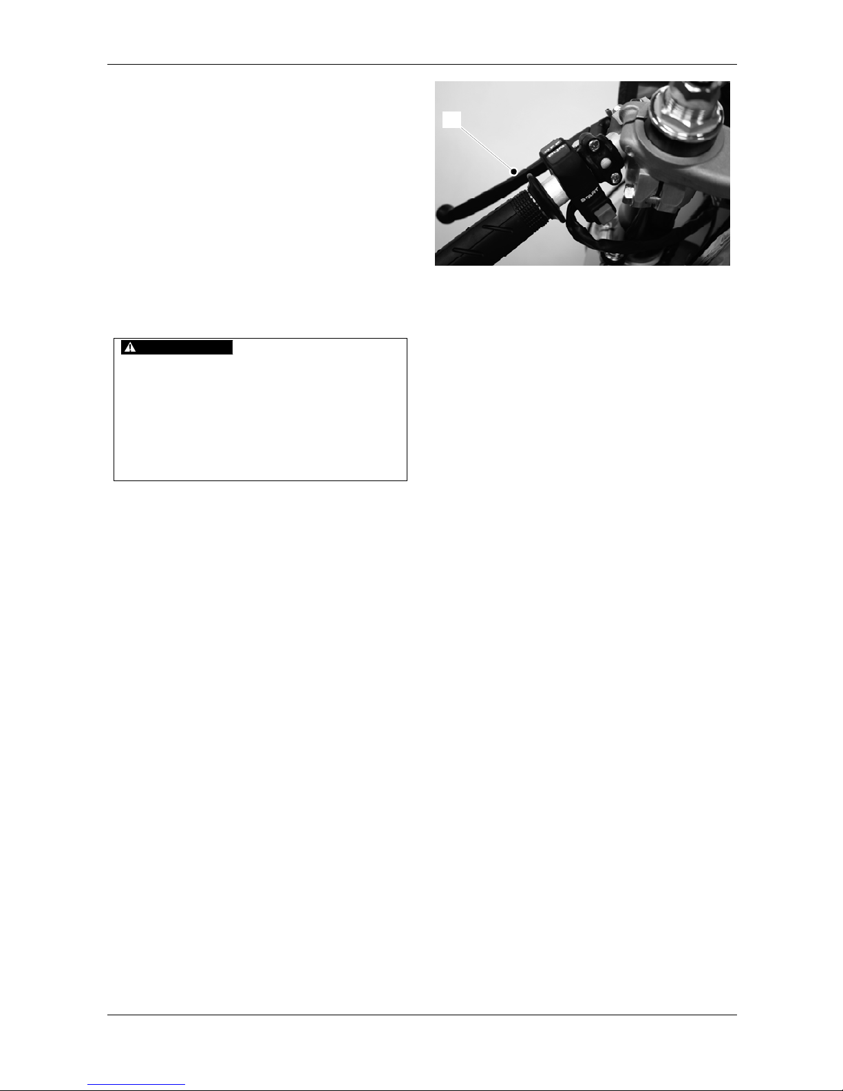
(1)
(1) Clutch lever
The fuel strainer is installed inside of the fuel valve which
is located below the fuel tank.
Perform the fuel strainer cleaning operation as follows;
1. Remove the seat cowl
2. Turn the fuel valve to OFF position and remove the
fuel tank
3. Drain gasoline from the fuel tank
4. Remove the fuel valve and clean the strainer screen
with treated oil
5. Open the fuel valve and air-blow it from outlet
6. Inspect the O-ring condition, then reassemble the
O-ring and the strainer screen into the fuel valve
7. Install the fuel valve with the outlet facing left.
Check the smooth operation of the clutch lever. Apply
grease to the pivot bolt and the clutch cable if necessary.
Inspect the clutch cable for damage.
Clutch
DENGER
DANGER
MAINTENANCE
PRINT EDITION 2.1
3-10
“888” will comes on for 3sec on the water temperature indicator
when you turn on the main switch to “RUN”, then it will start
indicating actual water temperature.
If the indicator shows “‐‐‐”, there will be the thermometer or
cable malfunctions.
(1) Water temperature indicator
Thermometer
Cover a part of radiator front with packing tape in case the
water temperature gets too low during running
A
ppropriate temperature: 70-80℃
(1) Radiator
(1) Drive chain slack
At the first break-in ride or after replacing the drive chain with
new one, inspect the initial slack and adjust the chain slack.
A
lways be careful not to catch your fingers between the drive
chain and sprockets.
Stop the engine and raise the motorcycle with the maintenance
stand.
Put the gear in neutral position, then measure the chain slack at
upper side of the chain run near the chain slider
Rotate the rear wheel and measure drive chain slack at a few
different areas.
If there is one or more areas have larger chain slack than other
areas, replace the drive chain with new one.
Drive chain slack inspection
Drive chain slack: 20±2mm
(1)
※Indicated chain slack value is out-of-factory value.
The value may differ depending on the chassis setting.
MAINTENANCE
PRINT EDITION 2.1
3-11
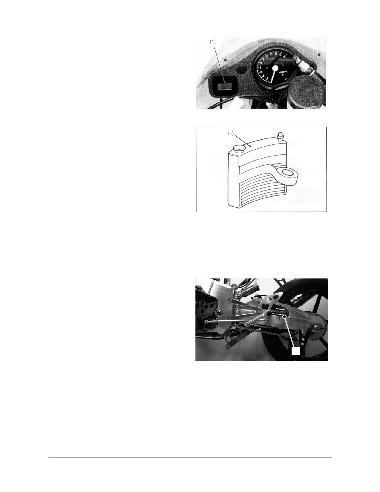
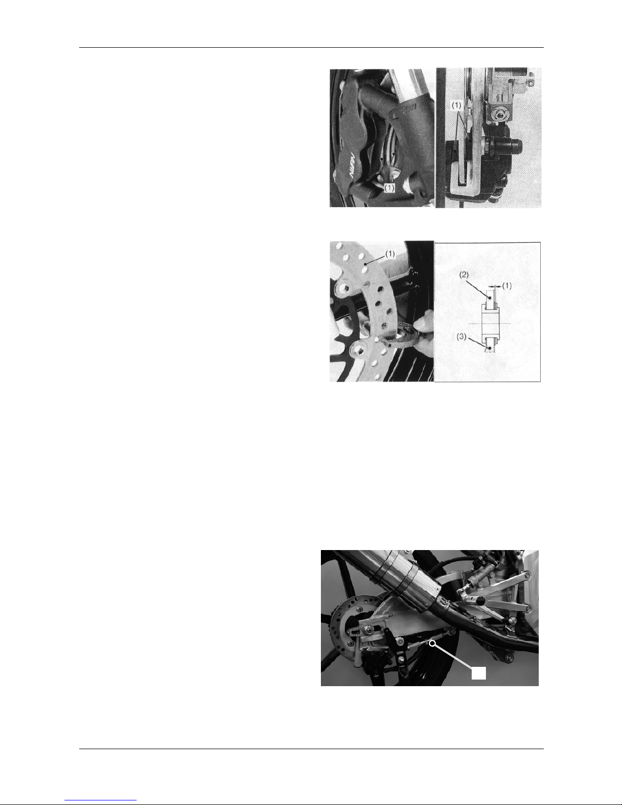
(1) Adjust bolt (2) Alignment mark
Loosen the rear axle nut.
Turn the drive chain adjust bolt and adjust the chain slack.
Turn the adjust bolt counter-clockwise to reduce the
amount of chain slack
CAUTION
Improper drive chain slack will lose not only the
engine power but also the motorcycle running
performance. Make sure to check the chain slack
before ride.
A
dvice
Inspect the drive chain slack again, and check if the wheel
rotate smoothly. Then, lubricate the drive chain.
A
fter performing the drive chain slack adjustment, check
alignment of wheels and adjust it if necessary.
Drive chain slack adjustment
Torque: 6 9N ・m(7.0kgf・m)
Tighten the axle nut to the specified torque.
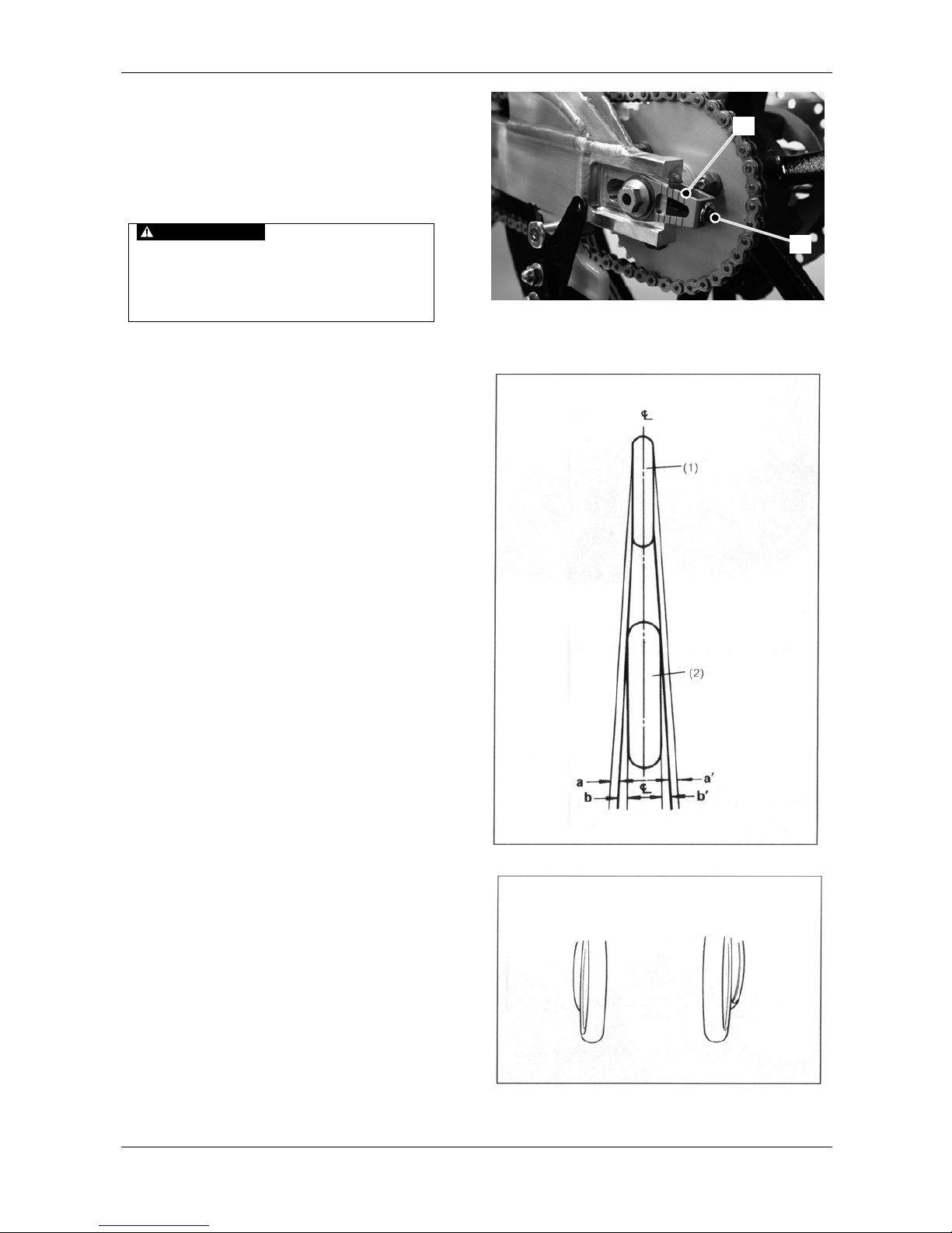
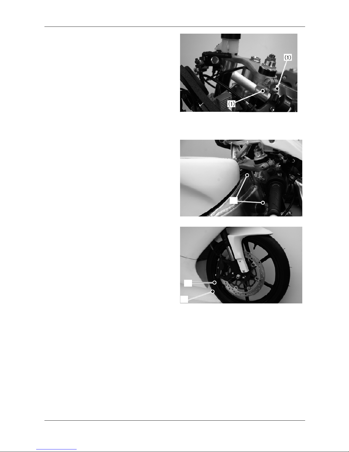
(1) Front tire (2) Rear tire
Wheel alignment
Inspect the alignment of wheels after performing the drive
chain slack adjustment.
1. Support the motorcycle upright on a level surface
2. Sit 1-2m behind the motorcycle and see both sides of the
wheels from axle down.
The handle is steered to the right
3. Steer the handle to left and right until the front wheel
becomes straight. Align the front edge of the rear tire
and rear edge of the front tire, then equalize the amount
of visible area of both side of the front tire.
Loose the axle nut and adjust the wheel adjustment by
adjusting the drive chain adjust bolts.
(1)
(2)
Straighten up the front wheel.
MAINTENANCE
PRINT EDITION 2.1
3-12
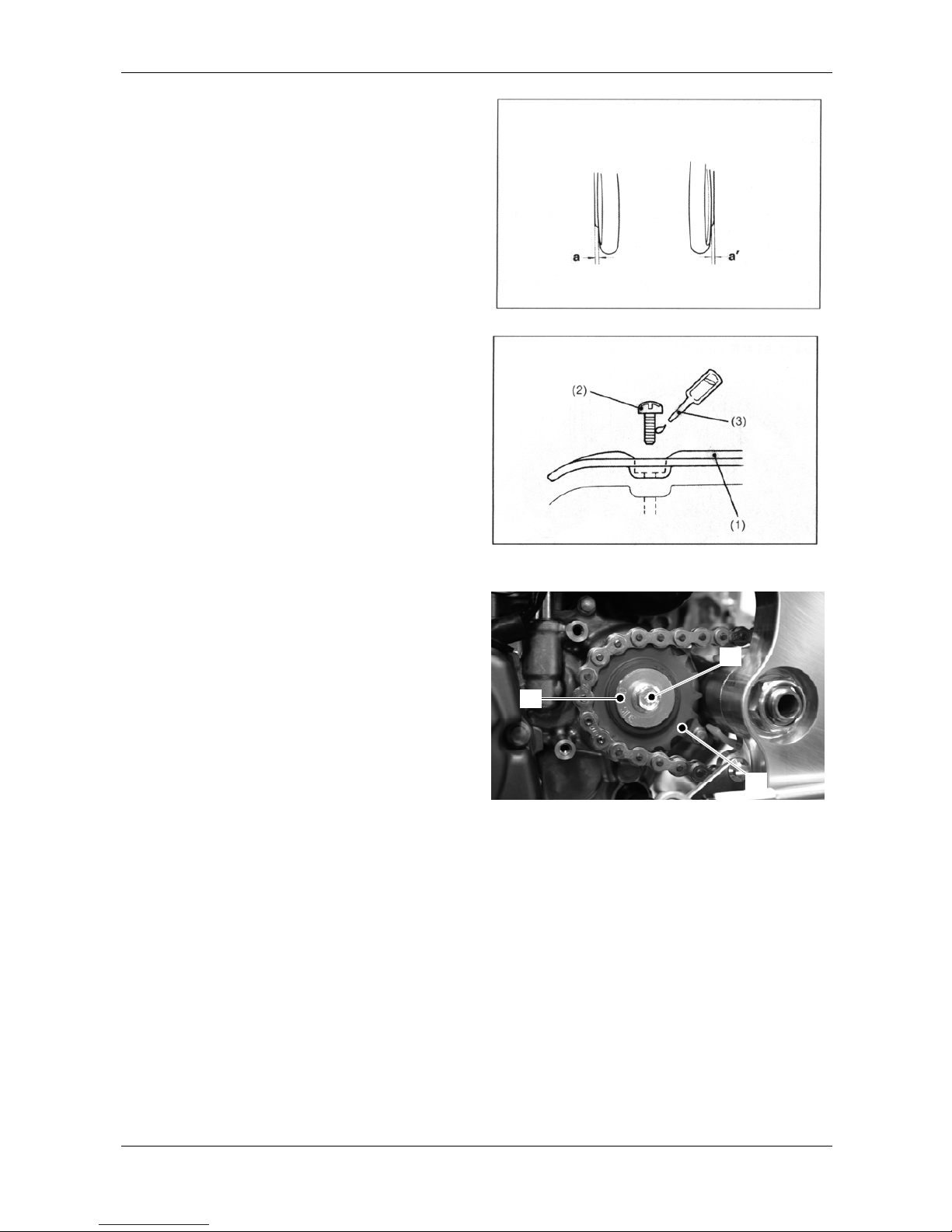
Equalize the [a] and [a’] appearance
(1) Drive chain slider (2) Screw (3) Locking agent
Drive chain slider
Check the chain slider for wear or damage.
Replace with new one if 2mm or more wear is noticed.
When you install a new drive chain slider, apply locking
agent to the screw and tighten it.
Re-tighten the screw after the first break-in ride.
Inspection
(1) Drive sprocket bolt (2) Spring washer (3) Drive sprocket
Drive / Driven sprocket
Drive sprocket change
Remove the lower front cowling.
Loosen the drive chain .
Put the motorcycle into the low gear and put the rear brake
on.
Remove following parts;
- Drive sprocket cover and chain guide
- Drive sprocket bolt
- Spring washer
- Drive sprocket
If inner surface of the spring washer has scratches, replace
it with new one.
Put the motorcycle into the low gear and put the rear brake
on.
Apply transmission oil to the thread and seating face of the
drive sprocket bolt.
Tighten the drive sprocket bolt to the specified torque.
Torque: 39 N・m (4.0kgf・m)
(1)
(2)
(3)
Handle is straight.
MAINTENANCE
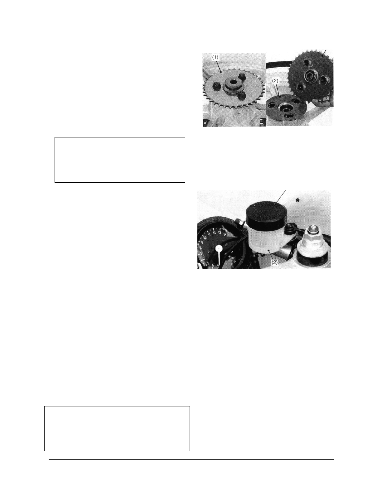
Driven sprocket change
Remove the rear wheel.
Remove the driven sprocket collar, driven sprocket and
washer.
Reverse sequence to install the driven sprocket.
※It may require shim adjustment at installation.
A
djust the drive chain slack.
Check the alignment of the wheels.
(1) Driven sprocket (2) Sprocket washer
Advice
・Make sure to check the driven sprocket nut tightening
after riding.
・The sprocket nuts must be replaced with new ones after
every 3 detaching and attaching operation.
・Always use the specified driven sprocket nuts
(1) Oil cup cap (2) Lower level line
Open the oil cup cap to release remaining pressure in the
reservoir and check the brake fluid level.
Remove the screws and oil cup cap.
If the level is near the lower level line, check the brake pads
for wear, and replace them if necessary.
Check the brake system for brake fluid leaks.
Front master cylinder
Brake fluid
・Replace the brake fluid every after 3 races.
・The brake fluid has high hygroscopicity. Performing the
brake fluid replacement on high humidity day is not
recommended.
・Replace the brake fluid every time after riding in wet
condition.
Brake fluid type: DOT4
Open the oil reservoir plug to release remaining pressure in the
reservoir and check the brake fluid level before ride.
A vinyl tube is used for the remaster cylinder reser voir.
Measure the brake fluid level from the top of the vinyl tube.
Rear master cylinder
Fluid level: 40-50mm
If the level is near the lower level line, check the brake pads for
wear, and replace them if necessary.
Advice
・The vinyl tube may get smeared with brake fluid. Clean the
vinyl tube regularly.
・Do not change the handling of the vinyl tube. Changing the
handling may damage the vinyl tube and cause brake fluid
leaks.
The vinyl tube deteriorates naturally. Replace it every 6 months.
PRINT EDITION 2.1
3-13
MAINTENANCE
PRINT EDITION 2.1
3-14
(1) Rear brake torque rod
Rear brake torque rod
The rear brake is floating type.
The rod length must be adjusted around the standard length.
The length is measured between the center of pillow balls.
Standard length: 160mm
(1)
(1) Brake pads
V
isually check the brake pads for wear.
Replace the brake pads if either pad is worn to the bottom
of the wear limit groove.
Use genuine HRC brake pads.
Brake pads
(1)
Brake disc
Brake system
(1) Floating amount
(2) Brake disc
(3) Hub
Brake lever position adjustment. (⇒1-4)
Brake pedal height adjustment. (⇒1-5)
Measure the brake disc thickness with a micrometer.
Service limits: Front: 3.5mm
Rear: 3.5mm
Measure the rear brake disc warpage with a dial indicator.
Replace the brake disc if one or more of above measurements
exceeds the service limits.
Relace the front brake disc.
Replace the rear brake disc.
Brake disc
Service limit: 0.3mm
Service limit: 0.5mm
Measure the floating amount of the front brake with a
feeler gauge.
Maximum length: 167mm
MAINTENANCE
PRINT EDITION 2.1
3-15
(1) Flange bolts
Handle bar / Head pipe bearings
Handle bar
Check the handle bars for bend, crack and damage.
Confirm that the handle bars are on appropriate position.
Make sure that the flange bolts of handle holder and fork
top bridge are securely tightened.
Torque: 2 3N ・m(2.3kgf・m)(8mm bolt)
Torque: 1 0N ・m(1.0kgf・m)(6mm bolt)
Handle bar position: Touching the fork top bridge bottom
(1) Head pipe bearings
Remove the steering damper.
Raise the front wheel off the ground and check that the
handle bar moves freely from side-to-side.
Check the head pipe bearings for play by grabbing the bottom of fork
legs and attempting to move the fork toward to engine.
If the movement isn’t smooth or excessive play has detected, check
the head pipe bearings and make adjustment.
Head pipe bearings
(1) Wheel (2) Tire
Wheels / Tires
・Choose suitable wheels and tires for race condition.
・Tire pressure influences the motorcycle controllability and
durability of the tires. Tire pressure should be checked
and adjusted before ride.
・Tire pressure should be checked when the tires are cold.
Check the cold tire pressure.
Tire pressure: Front: 1.8 kgf/c ㎡
Rear: 1.9kgf/c ㎡
Inspect the wheels for damage.
Check wheels for loose. If excessive play has detected,
replace with new one. (⇒2-2)
Check the axle runout and wheel bearing for damage.
(1)
(2)
(1)
MAINTENANCE
Front suspension
1. Inspect slide pipes and oil seals for dirt.
2. Check the entire assembly for signs of fork oil leaks. Replace the
oil seals with new ones before ride in case oil leak is detected.
3. Check the action of the forks by operating the front brake and
compressing the front suspension several times.
Advice
Damage on suspension components will cause severe problems on
the machine controllability, therefore, make sure to inspect them
before ride..
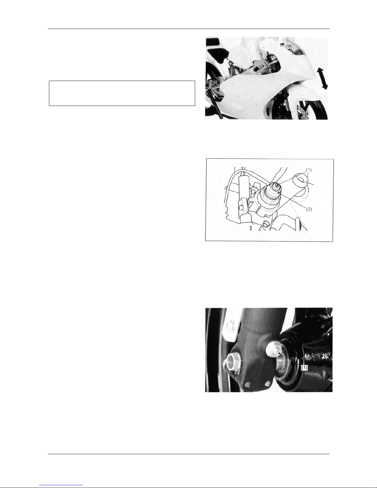
(1) Rebound adjuster (2) Pre-load adjuster
The front suspension is adjustable. Suitable settings for different
condition can be obtained by performing following adjustment
procedure.
・Rebound adjuster
The rebound adjuster is located in the center of the fork bolt.
Turn the rebound adjuster to change rebound damping force
(extending).
・Compression adjuster
The compression adjuster is located at behind the axle holder.
Turn the adjuster to change compression damping force
(compressing).
・Turn the pre-load adjuster to change initial pre-load of the fork
springs.
・Change the amount of fork oil contained in the fork to change fork
travel.
・Different springs can be chosen (harder or softer) to adjust the
front suspension.
Fork
Grease is applied to the slide pipes at shipping. This is not a sign
of oil leaks.
・Perform the first break-in ride for suspension.
・The first break-in ride must be performed under Out-of-factory
suspension setting.
・To sustain the performance of the suspension, overhaul at HRC
service shop at every 2,000km is recommended.
(1)
Compression adjuste
r
・To obtain maximum performance of the front fork, disassembly
and inspection operation is recommended every after 3hrs of
riding.
・Fork oil should be changed every 3 races or after 7.5hrs of
riding. See Chapter5 for oil change and oil level check
operation.
・Honda Ultra Cushion Oil Special or equivalent oil is
recommended to obtain maximum performance.
・Regularly inspect and clean the front suspension components.
Check the oil seal for dirt or foreign substance. Deterioration
of the fork oil should also be inspected.
・For suspension setting operation, only turn 1 step at a time
when you adjust the compression or rebound adjuster.
Always set the both fork legs simultaneously, and perform test
run after change the settings.
・Always go back to standard setting when you have trouble
getting wishful settings, then re-try the setting
PRINT EDITION 2.1
3-16
 Loading...