

Morita Root ZX II, Root ZX II OTR Module Operation Instructions Manual

Low Speed Handpiece for Apex Locator
OTR Module
Operation Instructions
ROOT ZX II OTR Module must be connected to ROOT ZX II Canal Measurement
Module, which is sold separately. This unit cannot be used as an independent unit.
This manual is for the OTR Module.
To measure a canal, refer to the manual for the Canal Measurement Module.


Thank you for purchasing the ROOT ZX II OTR Module.
For optimum safety and performance, read this manual thoroughly before using the unit and pay close attention to
warnings and notes. Keep this manual in a readily accessible place for quick and easy reference. This manual
contains essential safety information.
ATTENTION
*
• J. MORITA MFG. CORP. will not be responsible for accidents, instrument damage, or bodily injury
resulting from:
(1) Repairs made by personnel not authorized by J. MORITA MFG. CORP.
(2) Any changes, modifications, or alterations of its products.
(3) The use of products or instrument made by other manufacturers, except for those procured by J.
MORITA MFG. CORP.
(4) Maintenance or repairs using parts or components other than those specified by J. MORITA MFG.
CORP. and other than in their original condition.
(5) Operating the instrument in ways other than the operating procedures described in this manual or
resulting from the safety precautions and warnings in this manual not being observed.
(6) Workplace conditions and environment or installation conditions which do not conform to those
stated in this manual such as improper electrical power supply.
(7) Fires, earthquakes, floods, lightning, natural disasters, or acts of God.
• The useful life of the ROOT ZX II OTR Module is 6 years (based on self-certification) from the date of
shipment provided it is regularly and properly inspected and maintained.
• J. MORITA MFG. CORP. will supply replacement parts and be able to repair the product for a period of 10
years after the manufacture of the product has been discontinued.
* Inspect the unit every 6 months in accordance with “8. Inspection” on page 43.
* See “
10. Replacement Parts List” on page 46 and replace worn parts whenever necessary.
Operation 2018-06-21

Table of Contents
Page
Prevent Accidents ............................................................................................................................................... 1
1. Parts Identification ........................................................................................................................................ 3
2. Assembling the Unit ....................................................................................................................................... 5
Attaching OTR Module to Canal Measurement Module............................................................................ 5
Charging Battery ........................................................................................................................................ 6
3. Before Using the Unit ..................................................................................................................................... 7
Handpiece Cord .......................................................................................................................................... 7
Assembling Micromotor ............................................................................................................................. 8
Assembling File .......................................................................................................................................... 9
Attaching Contrary Electrode ..................................................................................................................... 9
Attaching Foot Switch .............................................................................................................................. 10
Calibration ................................................................................................................................................ 10
Checking the Function ............................................................................................................................... 11
4. Operating the Unit ....................................................................................................................................... 12
Overview of Features and Functions ........................................................................................................ 12
<OTR Mode> ........................................................................................................................................... 12
<Normal Mode> ....................................................................................................................................... 13
Root Canal Measurement (Two Methods) ................................................................................................ 14
Preparing the Root Canal .......................................................................................................................... 15
Liquid Crystal Display and Switches ....................................................................................................... 16
<OTR Mode> ..................................................................................................................................... 16
Torque Settings ............................................................................................................................... 17
Settings and Changing Memory ...................................................................................................... 17
<Normal Mode> ................................................................................................................................. 18
Torque Settings ............................................................................................................................... 19
Settings and Changing Memory ...................................................................................................... 19
Setting Memories for Other Functions ..................................................................................................... 20
<OTR Mode> ..................................................................................................................................... 20
<Normal Mode> ................................................................................................................................. 21
Meter Display ........................................................................................................................................... 22
Operating the Micromotor ........................................................................................................................ 23
Manual Mode Using the Foot Switch ....................................................................................................... 26
Manual Mode Using the Operation Switches ........................................................................................... 27
Replace Buit-in Electrode with Cap with External File Electrode ........................................................... 28
5. After Using the Unit ..................................................................................................................................... 30
6. Maintenance ................................................................................................................................................. 32
7. Replacement Parts, Transportation and Storage ...................................................................................... 41
Replace the Built-In Electrode ................................................................................................................. 41
Replacing the Battery ............................................................................................................................... 42
Transportation and Storage ....................................................................................................................... 42
8. Inspection ...................................................................................................................................................... 43
Regular Inspection .................................................................................................................................... 43
9. Troubleshooting ............................................................................................................................................ 44
10. Replacement Parts List .............................................................................................................................. 46
11. Technical Specifications ............................................................................................................................. 47
Specifications ........................................................................................................................................... 47
Symbols .................................................................................................................................................... 48
Operating, Transport and Storage Environments for the Main Unit and AC Adapter .............................. 49
Disposal .................................................................................................................................................... 49
Service ...................................................................................................................................................... 49
12. Electromagnetic Declaration ..................................................................................................................... 50
Essential Performance .............................................................................................................................. 53
Length ....................................................................................................................................................... 53
13. Warranty ..................................................................................................................................................... 54
Operation 2018-06-21

Prevent Accidents
Most operation and maintenance problems result from insufficient attention being paid to basic safety
precautions and not being able to foresee the possibilities of accidents.
Problems and accidents are best avoided by foreseeing the possibility of danger and operating the unit in
accordance with the manufacturer’s recommendations.
First thoroughly read all precautions and instructions pertaining to safety and accident prevention; then,
operate the equipment with the utmost caution to prevent either damaging the equipment itself or causing
bodily injury.
Note the meaning of the following symbols and expressions:
This warns that it may result serious injury of the patient or
operator if the instructions are not followed properly.
The user can not use in such a way that may result in serious injury
of the patient or operator.
This alerts the user to the possibility of damage to the equipment,
potential injury of the patient or operator, or important points
concerning operation and performance.
The user (e.g., healthcare facility, clinic, hospital etc.) is responsible for the management, maintenance
and use of medical device.
The ROOT ZX II OTR Module must only be used by dentists and other legally licensed professionals.
Do not use this equipment for anything other than its specified purpose.
Caution: Federal law restricts this device to sale by or on the order of a dentist. (for U.S.A.)
In Case of Accident
If an accident occurs, the ROOT ZX II OTR Module must not be used until repairs have been completed by
a qualified and trained technician authorized by the manufacturer.
Intended Operator Profile
This equipment must only be used by dentists and other legally licenced professionals
Patient Population
Age Child to Elderly
Weight N/A
Nationality N/A
Sex N/A
Health It is not intended for use on patients wearing pacemakers or ICDs.
Condition Conscious and mentally alert person. (Person who can stay still during treatment.)
• This device is not recommended for use in children under 12 years of age.
1
Operation 2018-06-21

• No modification of this equipment is allowed.
• This unit must not be connected to or used in combination with any other apparatus or system. It must
not be used as an integral component of any other apparatus or system.
J. MORITA MFG. CORP. will not be responsible for accidents, equipment damage, bodily injury or any
other trouble which results from ignoring this prohibition.
• Do not injure your fingers when inserting or removing files.
• Do not use damaged file holders; an accurate measurement cannot be made with a damaged file holder.
• When continuous tone is heard while the main power switch is on and without any operation, some
electrical part may be malfunction. Do not use the unit and send the unit to J. MORITA OFFICE for
repairing.
• This unit is for prescription use only.
• A rubber dam should be used when performing endodontic treatment.
• Caution: US Federal law restricts this unit to sale by or on the order of a dentist in U.S.A.
• The ROOT ZX needs special precaution regarding EMC and needs to be installed and put into service
according to the EMC information provided in the Accompanying Documents.
• Portable and mobile RF communications equipment can affect the ROOT ZX II.
• The ROOT ZX II should not be used adjacent to or stacked with other equipment and that if adjacent or
stacked use is necessary, the ROOT ZX II should be observed to verify normal operation in the
configuration in which it will be used.
• Do not use this unit in conjunction with an electric scalpel or on patients who have a pacemaker.
• Do not use this unit in the medical operation room.
• Blocked canals cannot be accurately measured.
• This unit must not be connected to or used in combination with any other apparatus or system. It must
not be used as an integral component of any other apparatus or system.
J. MORITA MFG. CORP. will not be responsible for accidents, equipment damage, bodily injury or any
other trouble which results from ignoring this prohibition.
• Illumination devices such as fluorescent lights and the Film viewer which use an inverter can cause the
ROOT ZX II to operate erratically. Do not use the ROOT ZX II near devices such as these.
• Electromagnetic wave interference could cause this unit to operate in an abnormal, random and
possibly dangerous manner. Cellular phone, transceivers, remote controls and all other devices which
transmit electromagnetic waves located inside the building should be turned off.
• Do not perform maintenance while using the instrument for treatment.
Operation 2018-06-21
2

1. Parts Identification
OTR Module is used as a low voltage motor and as a base unit for other electronic dental devices.
OTR Module
Canal Measurement Module
(Sold separately)
Liquid Crystal Display
Handpiece Cord
AC Adapter
Cord Clips
Foot Switch
* Connect OTR Module to Canal Measurement Module.
* OTR Module cannot be used as an independent unit.
Micromotor
Contra Angle
Contrary Electrode
(Canal Measurement Module accessory)
3
Operation 2018-06-21
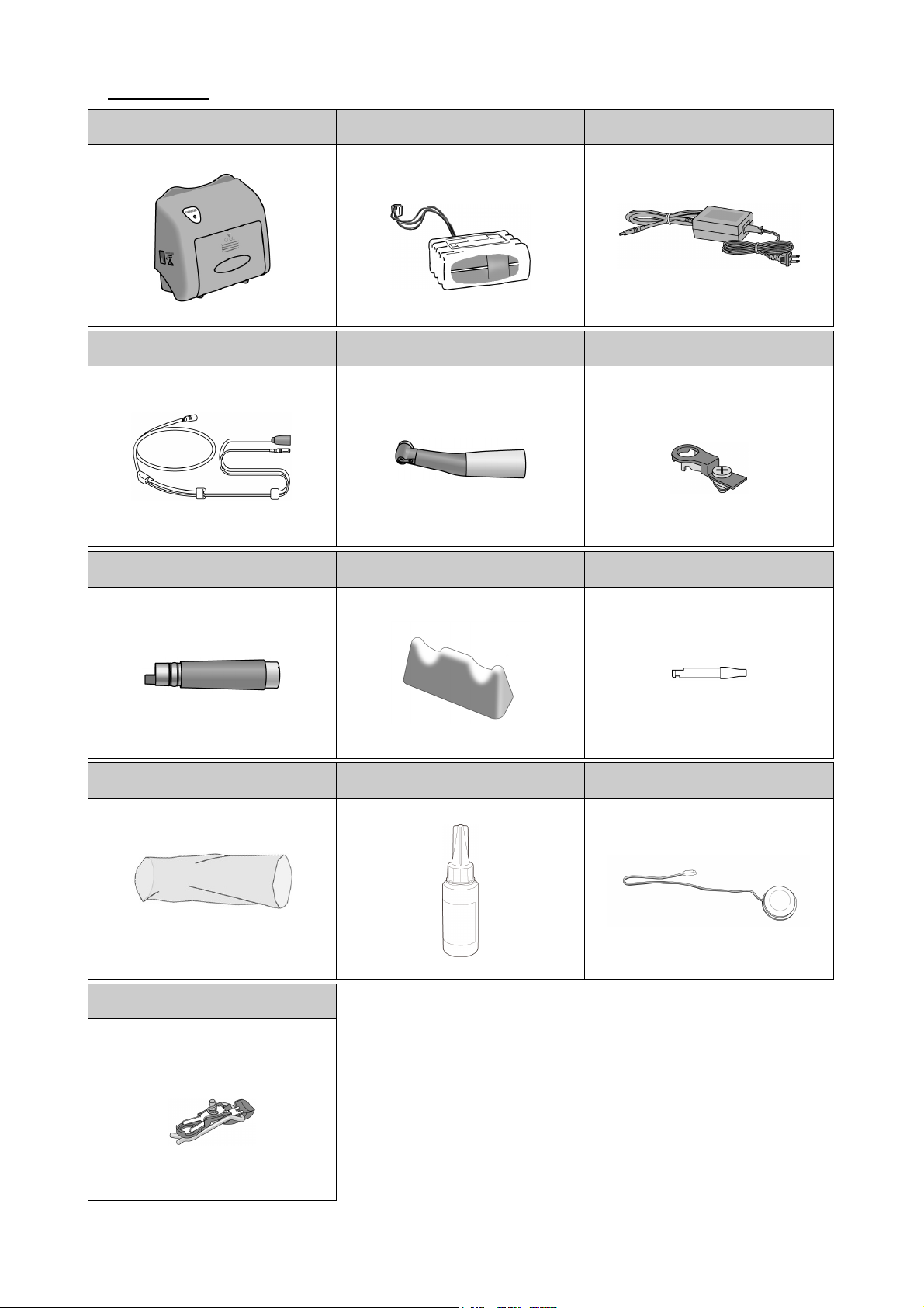
Components
OTR Module (1)
(Pre-installed in OTR Module)
Handpiece Cord (1) Contra Angle (1) Built-in Electrode (1)
Micromotor (1) Handpiece Rest (1) Guide Bar (1)
Battery (1) AC Adapter
(Pre-installed in Contra Angle)
Plastic Sleeve (20) LS Oil (1) Foot Switch (1)
Cap with External File Electrode
(Sold Separately)
Operation 2018-06-21
4
2. Assembling the Unit
* OTR Module will not operate unless connected to Canal Measurement Module.
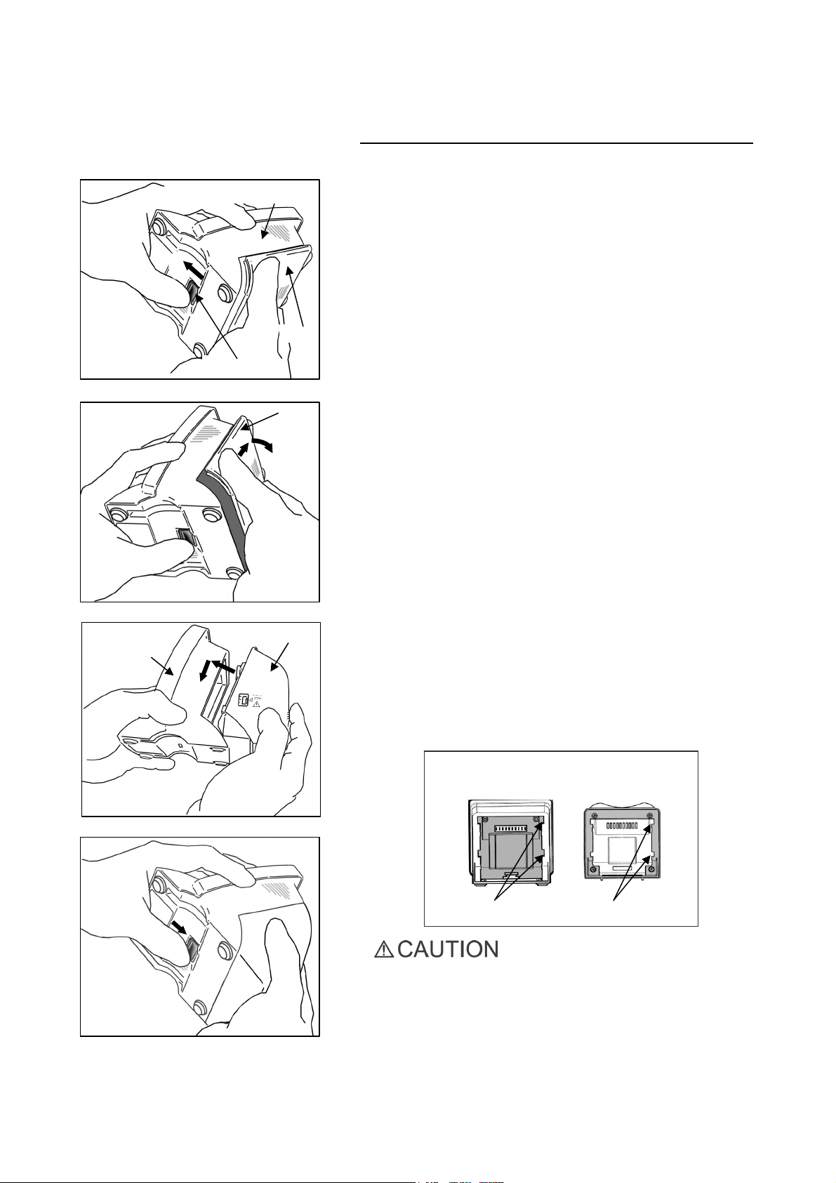
Attaching OTR Module to Canal Measurement Module
1. Hold the cover and slide the stopper on the bottom towards
Canal Measurement Module
1
Cover
Stopper
Cover
the liquid crystal display.
2. Slide the cover in the direction indicated by the arrow in the
illustration and remove it from Canal Measurement Module.
Canal
Measurement
Module
4
3
2
OTR Module
* The cover and batteries will not be used.
3. Line up the tabs on OTR Module with the notches in Canal
Measurement Module and put the two modules together.
4. Slide OTR Module all the way down until it is securely
attached.
Canal Measurement
Module
OTR Module
Notches Tabs
• If the catch on the bottom is not back in its original place
after attaching, push it in the direction shown by the arrow
in the illustration.
• After installation, give OTR Module a light tug to confirm
it is securely attached.
5
Operation 2018-06-21
Charging Battery
The battery is built into OTR Module.
• The battery is not charged when the unit is shipped from
the factory and must be charged before using the unit.
• If the plug for the AC adapter does not fit the electrical
power receptacle, it is the user’s responsibility to find a
suitable plug adapter.
• Use only the AC adapter made for ROOT ZX II.
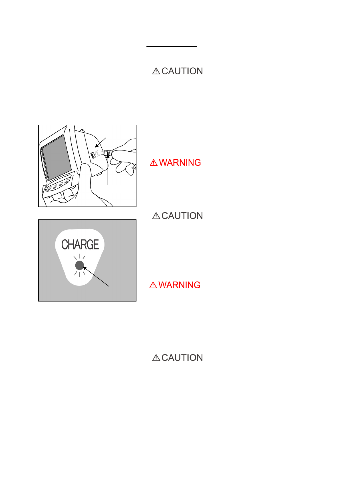
OTR Module
AC Adapter Plug
1. Line up the arrow on the AC adapter’s connector with the
small triangle above its jack on the side of OTR Module and
plug it in. Then plug the adapter into the electrical power
receptacle.
• Do not use the unit when the AC adapter is connected.
2. The amber Charge LED on the back of OTR Module starts
flashing on and off and then, after a few seconds, it will stop
flashing and stay on to show that the battery is being charged.
It takes about 60 minutes to fully charge the battery.
Amber Charge LED On
• If [F.02] appears in the display, noise has been detected.
Turn the unit off and then back on again. If [F.02] still
appears, stop using the unit and contact your local dealer
or J. MORITA OFFICE.
3. Amber Charge LED goes out when the battery is fully
charged.
4. Disconnect the AC adapter from OTR Module and unplug it.
• Never operate the unit with an external power supply.
• If an electrical storm occurs while the battery is being
charged, do not touch the AC adapter or the charger’s
power supply cord as there would be a risk of receiving an
electric shock.
• The AC adapter must be located outside the patient
environment (2.0m / 6ft. around the patient location) when
the AC adapter is connected.
• Do not pull or yank the cord when disconnecting the AC
adapter.
Operation 2018-06-21
6

3. Before Using the Unit
Handpiece Cord
Handpiece Cord Plug
OTR Module
Cord Clips
Plug in until the tip of the
arrow reaches the
surface marked with the
small triangle (▼).
1. Line up the arrow on the handpiece cord’s plug with the
little triangle above its jack and plug it all the way in
until the arrow disappears inside the jack.
• Handle OTR Module carefully; do not drop, bump or
expose the unit to other kinds of impacts or shocks.
Rough handling could cause damage.
• Make sure the plug is all the way in; otherwise there could
be measurement, operation or display problems.
• Do not drop anything on or bang the plug after it has been
inserted into the jack.
2. Slide the cord clips one at a time down to where the
cords fork so that they do not interfere with the use of
the cord for the contrary electrode.
Fork
Handpiece Cord
• Sliding the cord clips with too much force could cause the
tube to wrinkle or twist, making it hard to slide the clips.
It could also cause the cord for the contrary electrode to
come off.
• It may be hard to slide the clips if the cord is wet with
ethanol or some other liquid.
7
Operation 2018-06-21
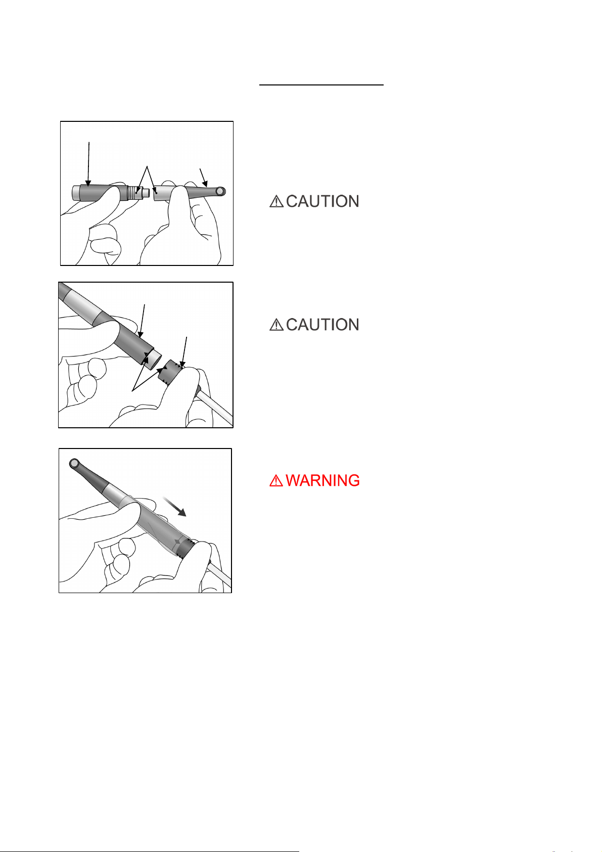
Micromotor
Dots (●)
Micromotor
Contra Angle
Assembling Micromotor
* Contra angle must be lubricated with the LS Oil before using
for the first time. See “
1. Line up the dots on the micromotor and contra angle and slide
the contra angle straight onto the micromotor until it clicks
securely into place. The contra angle has a simple snap-on
connection.
• After attaching contra angle into the micromotor, give the
contra angle a light tug to confirm it is securely attached.
2. Line up the triangle marks to connect the micromotor to
handpiece cord.
6. Maintenance” on page 32.
▲Triangle Marks
Handpiece Cord
• After attaching the micromotor into handpiece cord, give
the micromotor a light tug to confirm it is securely
attached.
3. Put a plastic sleeve on the micromotor portion.
• Plastic sleeves must be replaced after each patient.
Operation 2018-06-21
8
File Release Button
Assembling File
* Use only nickel-titanium files for root canal preparation.
• Never use stretched, deformed or damaged files.
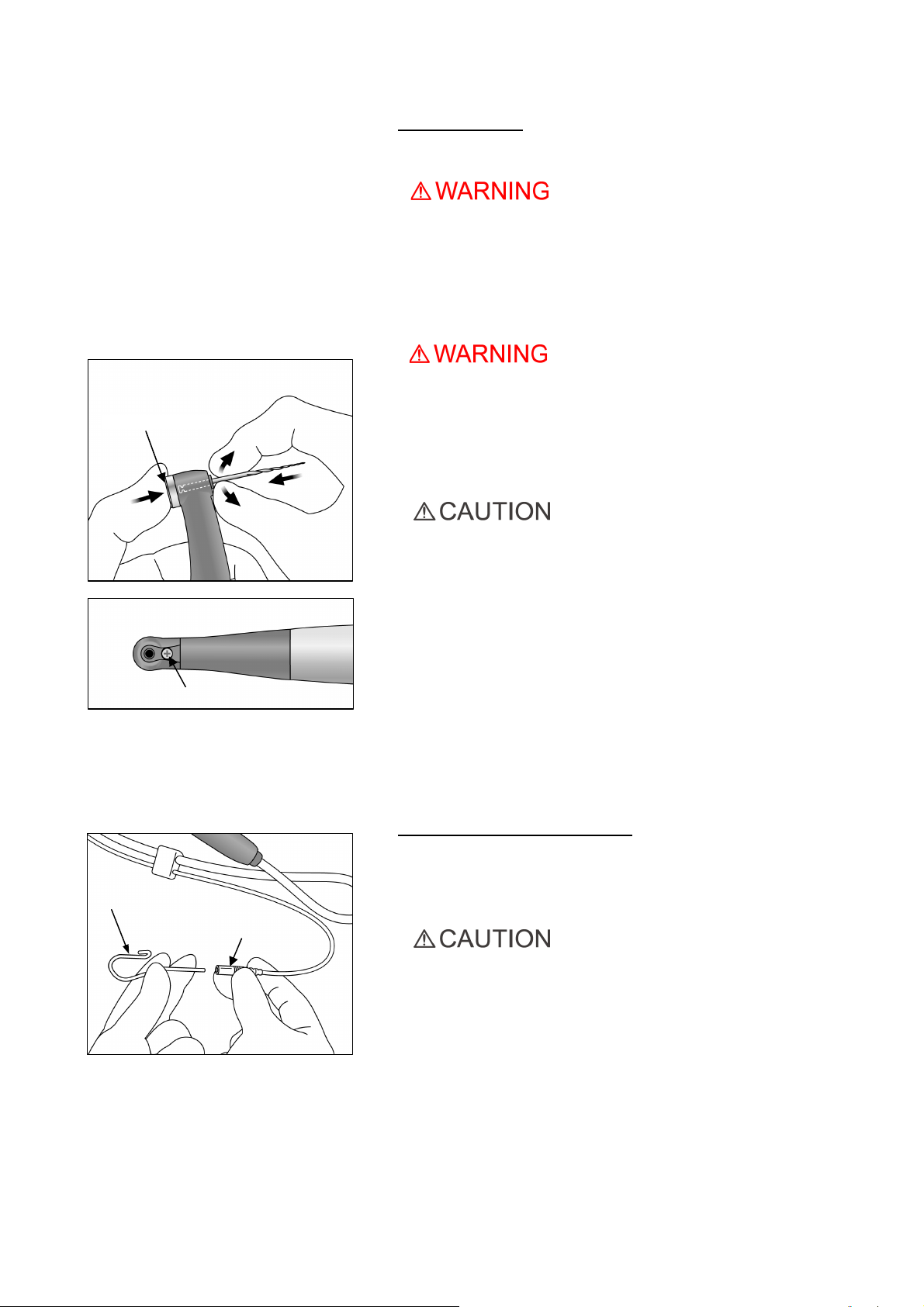
1. Hold down the file release button on the contra angle and
insert the file. Turn the file back and forth until it is lined up
with interior latch groove and slips into place. Release the
button to lock the file into the contra angle.
• Give the file a light tug to confirm it is securely held in place.
If the file is not securely placed, it could come out and injure
the patient.
Make sure the screw is properly tightened up. It could come
•
out and be swallowed if it is loose; also canal measurements
may not be accurate.
Screw
Contrary Electrode
• Use caution when inserting and removing files to avoid
injury to fingers.
• Inserting and removing files without holding the file
release button may damage the chuck.
• If there is no electrical conductivity between the file and its
shank, replace the cap with the one that has an external
file electrode. (See page 28.)
• Do not clip the file electrode to the cutting part of the file.
• The file electrode cannot be attached onto some files.
• Do not use files with shanks larger than the ISO standard.
ISO Standard: Diameter 2.334 to 2.350 mm
Attaching Contrary Electrode
Insert the contrary electrode (lip clip) into the connector of the
handpiece cord. (The contrary electrode is an accessory
provided with Canal Measurement Module.)
Connector
• Always hold the connector to connect or disconnect cords.
9
Operation 2018-06-21
Attaching Foot Switch
Foot Switch Plug
Insert the foot switch plug all the way into its jack on the side of
OTR Module.
[This jack is marked with a small triangle (►) pointing right.]
• Always hold the connector to connect or disconnect cords.
* Operate the handpiece with the foot switch if a canal cannot
be accurately measured.
Calibration
* Before using right after purchase, whenever the motor handpiece
or contra angle has been replaced, or if the motor alternates
between forward and reverse rotation outside the canal, calibrate
the instrument in the following way.
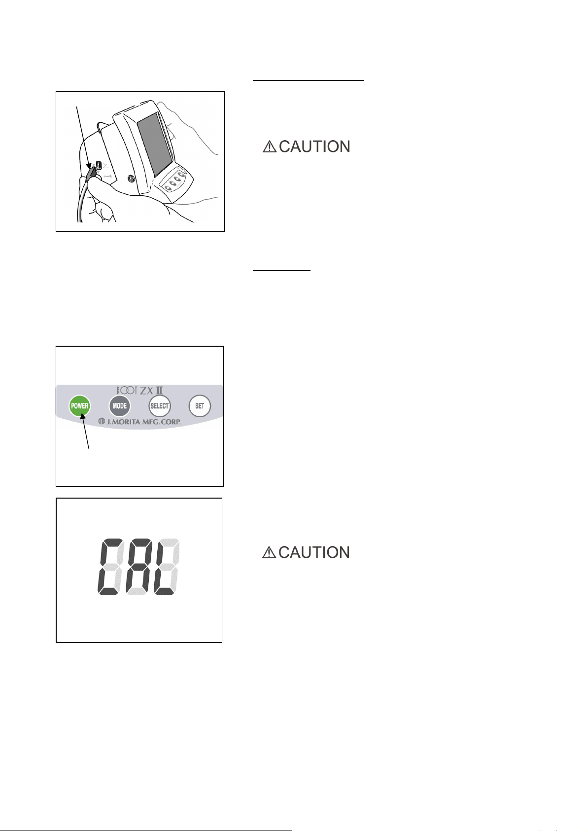
1. Press the POWER switch and turn the unit on.
POWER Switch
2.When the M1 display comes up, hold the SELECT switch.
While still holding the SELECT switch, press and hold
the MODE switch until “CAL” is displayed in the lower
left part of the display.
3. Hold the motor with the file pointing down and press
the Set switch.
The motor will start running and adjust itself.
• Do not exert any load on the file while the motor is running
(about 15 seconds).
• To perform calibration, attach an ordinary file.
4. When the motor stops, press the POWER switch to turn the unit off.
Operation 2018-06-21
10
POWER Switch
Checking the Function
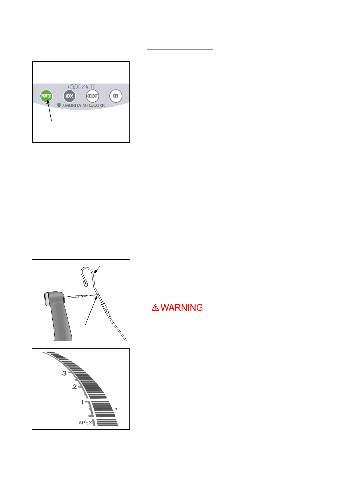
1. Press the POWER switch to turn the unit on. Display used for
root canal preparation will appear.
* The unit will automatically turn off after 10 minutes of
non-use.
* Wait at least 3 seconds after the power goes off before
turning it back on again.
* Do not turn the power on while stepping on the foot switch.
* If there is a sequence of single and double beeps right after
you turn the unit on, the built-in electrode needs to be
replaced. When connecting the motor handpiece to the
handpiece cord and using the module in conjunction with
the root canal measurement function, clean the rotor axle
and replace the electrode before making any measurements.
(See page 41.)
After replacing the built-in electrode, press the SET switch
while the alarm is beeping. Then the beeper alarm will be
OFF until next estimated replacement timing.
Contrary Electrode
File Holder Contact
2. Check that the handpiece cord is properly plugged into the
jack.
3. Check that the contra angle is securely attached to the
micromotor.
4. Check that the file is properly installed. Give it a light tug to
confirm.
5. Check that the contrary electrode is attached to the connector
of the handpiece cord.
6. Contact the file with contrary electrode and check that all the
root canal length indicator bars on the display are lit, the word
“APEX” flashes and audible beep becomes continuous. Use
caution when contacting the file with contrary electrode as the
file starts to rotate as soon as the file touches the contrary
electrode.
• Check the ROOT ZX II’s operation before each patient. If
the indicators in the display do not all appear normally, the
instrument may not be able to make an accurate
measurement. In this case, stop using the instrument and
have it repaired.
11
Operation 2018-06-21

4. Operating the Unit
•
If there is a lightning storm while the battery is being charged, do not touch the main unit, the AC
adapter or the main power cord; you could get a shock.
• Stop using the instrument and have it repaired if the display does not appear properly or if the instrument
suddenly turns off (except in the case where it automatically turns itself off after 10 minutes of not being
used).
Overview of Features and Functions
The combination of OTR Module with Canal Measurement Module allows the micromotor to be
controlled in a variety of ways. The root canal can be enlarged and prepared with great precision and
delicacy.
Easy Operation
Press the POWER switch to turn the unit on and press the MODE switch to select any one of three memories.
Each memory can be set for different motor control parameters. The desired set of parameters can be easily
selected by pressing MODE switch button.
<OTR Mode>
If the file torque is less than the set value, the file will keep rotating in the forward direction. When the file torque is
more than the set value, the file will automatically start rotating 90º in reverse and 180º forward repeatedly.
Furthermore, the OTR mode can set various motor controls as described below.
▪ File Rotation Speed
There are 3 speed settings: 100, 300, and 500 rpm.
▪ Auto Start and Stop
The file automatically starts rotating when inserted inside the canal (when meter reading is at least 2 lines)
and stops when it is withdrawn.
▪ Auto Apical Reverse and Auto Apical Stop (You may also turn off this function.)
The motor will stop (Auto Apical Stop) or reverse (Auto Apical Reverse) itself when the file tip reaches the
point specified by the meter reading (bar) selected to indicate the working length.
You may select either Stop or Reverse.
▪ Torque Setting
The torque for the OTR function can be set at 4 different levels.
* These torque values vary somewhat depending on the condition of the micromotor and the gears.
Torque Line
1 20 0.2
2 40 0.4
3 60 0.6
4 100 1.0
Torque (g·cm)
Approx.
Torque (N·cm )
Approx.
▪ Adjustable sound volume
Volume of audible signal can be adjusted.
▪ The unit will automatically go into the root canal measurement mode if it detects any abnormality such as the
one caused by electrical noise. However, it will return to the normal mode when the file is taken out of the
root canal.
▪ The motor handpiece can also be operated with the foot switch.
Operation 2018-06-21
12

<Normal Mode>
If the file torque is less than the set value, the file will keep rotating in the forward direction. When the file torque is
more than the set value, the file will automatically start rotating in reverse direction.
Furthermore, the Normal mode can set various motor controls as described below.
▪ File Rotation Speed
8 speeds setting from 150 rpm to 800 rpm can be selected.
▪ Auto Start and Stop
The file automatically starts rotating when inserted inside the canal (when meter reading is at least 2 lines)
and stops when it is withdrawn.
▪ Auto Apical Reverse and Auto Apical Stop (You may also turn off this function.)
The motor will stop (Auto Apical Stop) or reverse (Auto Apical Reverse) itself when the file tip reaches the
point specified by the meter reading (bar) selected to indicate the working length.
You may select either Stop or Reverse.
▪ Setting Stopping Time before the File Reverses
When Auto Apical Reverse function is triggered, the interval between the file stopping the rotation and
reversing can be set.
▪ Torque Setting for Auto Torque Reverse
There are 11 settings available for the value of the torque that will trigger the Auto Torque Reverse function.
The Auto Torque Reverse function can also be turned off. Please refer to the table below.
* These torque values vary somewhat depending on the condition of the micromotor and the gears.
Torque Line
1 20 0.2
2 40 0.4
3 60 0.6
4 100 1.0
5 150 1.5
6 180 1.8
7 250 2.5
8 300 3.0
9 350 3.4
10 400 3.9
11 500 4.9
ALL OFF OFF
Torque (g·cm)
Approx.
Torque (N·cm )
Approx.
* Setting the torque level for line 10 or 11 could result in the file preparing into the canal wall and locking up.
▪ Auto Apical Slow Down
The file automatically slows down as it approaches the apex so that the region near the apical foramen can
be treated with a slow gentle rotation. This function can also be turned off.
The rate at which the file slows down depends on the speed setting. The charts below show the rate at
which the file slows down.
▪ Auto Torque Slow Down Function:
The file slows down automatically as the torque on it approaches the set limit. This function can be turned
off.
▪ Adjustable sound volume
Volume of audible signal can be adjusted.
▪ The unit will automatically go into the root canal measurement mode if it detects any abnormality such as the
one caused by electrical noise. However, it will return to the normal mode when the file is taken out of the
root canal.
▪ The motor handpiece can also be operated with the foot switch.
13
Operation 2018-06-21
Root Canal Measurement (Two Methods)
Plug the probe cord into Canal Measurement Module and connect the file
holder and contrary electrode.
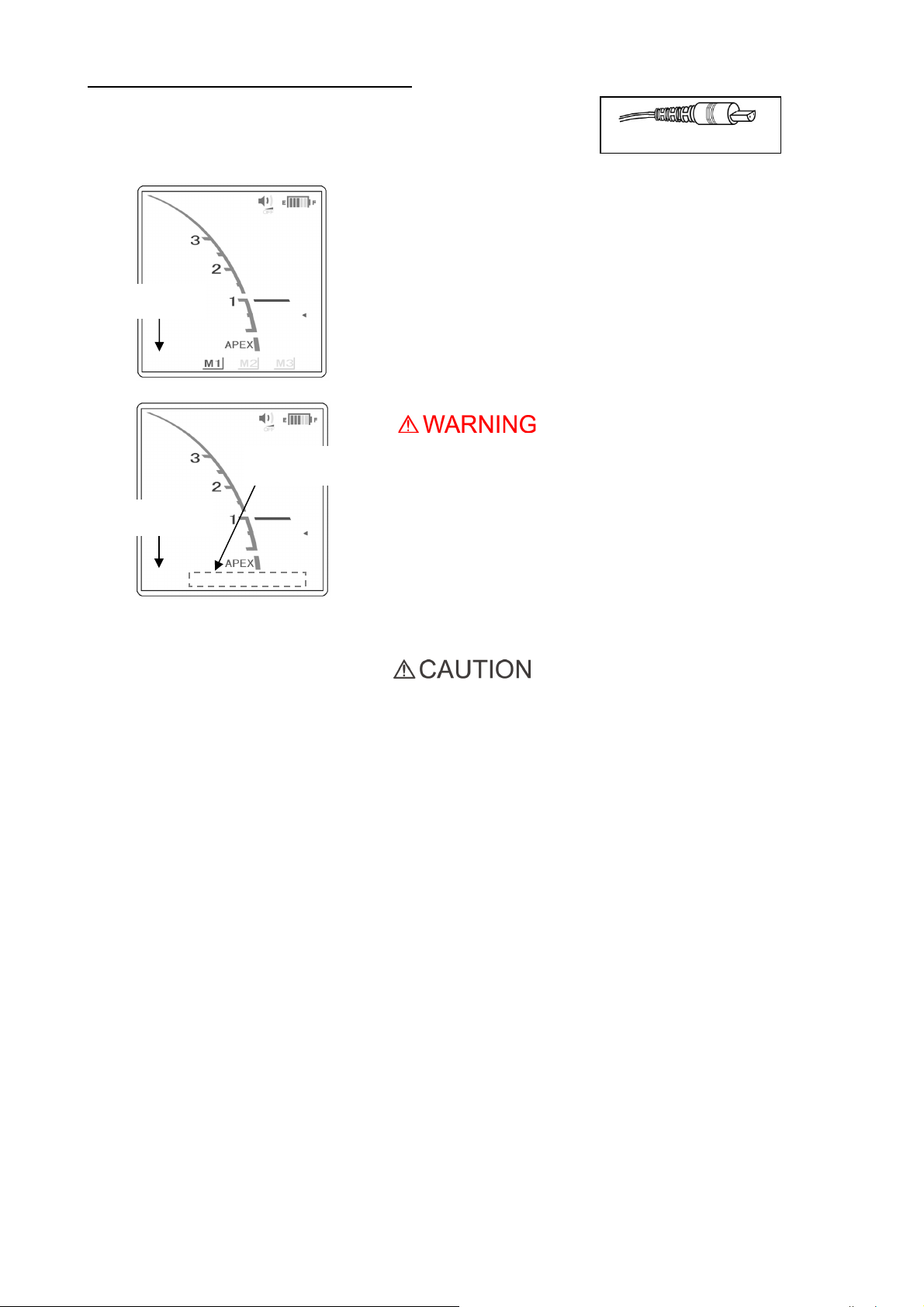
a: Detach the micromotor from handpiece cord. Select M1, M2
or M3 with pressing the MODE switch and measure length of a
root canal. (Refer to the operation manual for Canal
Measurement Module.)
Rotation speed
is not displayed.
b: Leaving the micromotor connected and press the MODE switch
until the speed and memory displays disappear. (Refer to the
operation manual for Canal Measurement Module.)
Memories are not
displayed.
Rotation speed is
not displayed.
• Make sure that the contrary electrode, file holder, handpiece file
electrode etc. do not come into contact with an electric power
source such as an electrical socket. This could result in a
severe electrical shock.
• Before measuring length of a root canal, make sure that the
rotation speed does not appear on the display. If the rotation
speed appears on the display, the unit is set for root canal
preparation mode, and the handpiece will start running. This
could result in an injury.
Probe Cord Plug
• It is best to disconnect the handpiece when measuring the
root canal.
• Remove the file from the contra angle when taking a
measurement.
Operation 2018-06-21
14
 Loading...