

Morita Root ZX II User manual

Dental root canal measurement and treatment unit
Low Speed Handpiece Module
Operation Instructions
* Low Speed Handpiece Module must be connected to Canal Measurement Module,
which is sold separately. This unit cannot be used as an independent unit.
This manual is for Low Speed Handpiece Module.
To measure a root canal refer to the manual for Canal Measurement Module.
USP. 5980248
USP. 5897315
USP. 5902105
USP. 5096419
USP. 5211556
USP. 5295833
DBP. PAT. 4126753
DBP. PAT. 4139424
DBP. PAT. 4232487
KOREA PAT. 159070
JAPA N PAT. 2873722
JAPA N PAT. 2873725
JAPA N PAT. 3071245
JAPA N PAT. 3071270
JAPA N PAT. 3113109
JAPA N PAT. 3113095
JAPA N PAT. 3213484

Thank you for purchasing ROOT ZX II Low Speed Handpiece Module.
For optimum safety and performance, read this manual thoroughly before using the unit and pay
close attention to warnings and notes. Keep this manual in a readily accessible place for quick and
easy reference. This manual contains essential safety information.
CONTENTS
Page
1. Prevent Accidents.................................................................................................................... 1
2. Parts Identification................................................................................................................. 5
3. Assembling the Unit............................................................................................................... 6
4. Before Using the Unit............................................................................................................. 8
5. Operating the Unit ................................................................................................................11
6. After Using the Unit..............................................................................................................22
7. Sterilization, Replacement Parts and Storage....................................................................24
I
(1) Sterilization ................................................................................................................24
(2) Replacement Parts......................................................................................................26
(3) Storage ........................................................................................................................27
Maintenance and Inspection.................................................................................................28
8.
9. Troubleshooting......................................................................................................................29
10. Replacement Parts List.........................................................................................................31
11. Technical Specifications ........................................................................................................32
12. Warranty.................................................................................................................................37
Operation 12. 21. ’04
Page 1
1. Prevent Accidents
Most operation and maintenance problems result from insufficient attention being paid to basic
safety precautions and not being able to foresee the possibilities of accidents.
Problems and accidents are best avoided by foreseeing the possibility of danger and operating the
unit in accordance with the manufacturer’s recommendations.
Note the meaning of the following symbols and expressions:
WARN ING This warns that it may result serious injury of the patient or
operator if the instructions are not followed properly.
PROHIBITION
NOTE
This alerts the user to the possibility of damage to the equipment,
The user ( e.g. the hospital, clinic etc. ) is the party responsible for the maintenance and proper
operation of ROOT ZX II Low Speed Handpiece Module.
ROOT ZX II Low Speed Handpiece Module must only be operated by dentists and other legally
licensed professionals.
The user can not use in such a way that may result in serious
injury of the patient or operator.
potential injury of the patient or operator, or important points
concerning operation and performance.
Do not use this equipment for anything other than its specified purpose.
Operation 12. 21. ’04

WARN ING
•
This unit must not be connected to or used in combination with any other apparatus or
system. It must not be used as an integral component of any other apparatus or system.
J. Morita Mfg. Corp. will not be responsible for accidents, equipment damage, bodily
injury or any other trouble which results from ignoring this prohibition.
•
Do not injure your fingers when inserting or removing files.
•
Do not use damaged file holders; an accurate measurement can not be made with a
damaged file holder.
•
When continuous tone is heard while the main power switch is on and without any
operation, some electrical part may be malfunction. Do not use the unit and send the unit
to J. Morita office for repairing.
•
This unit is for prescription use only.
•
A rubber dam should be used when performing endodontic treatment.
•
Caution: US Federal law restricts this unit to sale by or on the order of a dentist in U.S.A.
•
Do not use the unit when the AC adapter is connected. ( see page 7, 22 )
•
Never operate the unit with an external power supply. ( see page 7, 23 )
•
If an electrical storm occurs while the battery is being charged, do not touch the AC
adapter or the charger’s power supply cord as there would be a risk receiving an electric
shock. ( see page 7, 23 )
•
After attaching contra angle to the micromotor, give the micromotor a light tug to confirm
it is securely attached. ( see page 8 )
After attaching the micromotor to handpiece cord, give the micromotor a light tug to
•
confirm it is securely attached. ( see page 8 )
Plastic sleeves must be replaced after each patient. ( see page 8 )
•
Never use stretched, deformed or damaged files. ( see page 9)
•
•
Give the file a light tug to confirm it is securely held in place. If the file is not securely
placed, it could come out and injure the patient. ( see page 9)
•
Take care to avoid the risk of a file being swallowed by the patient. ( see page 9)
•
Check the unit’s operation before each patient. If the indicators in the display do not
appear normally, the unit may not be able to make an accurate measurement. In this
case, stop using the unit and have it repaired. ( see page 10)
•
When measuring the length of a root canal, make sure that the file electrode does not
come into contact with an electric power source such as an electrical socket. This could
result in a severe electrical shock. ( see page 12)
•
Before measuring length of a root canal, make sure that the rotation speed does not
appear on the display. If the rotation speed appears on the display, the unit is set for
root canal preparation mode, and the handpiece will operate. ( see page 12)
•
When shaping a root canal, make sure that the file or contrary electrode does not come
into contact with an electric power source such as an electrical socket. This could result in
a severe electrical shock. ( see page 13)
•
Check the settings on the display after selecting memories. ( see page 14 )
•
In some cases such as a blocked root canal, a measurement can not be made.( see page 16 )
•
Accurate measurement is not always possible, especially in cases of abnormal or unusual
root canal morphology; make sure to take an x-ray to check the measurement results.
( see page 16 )
•
Stop using the unit immediately if it does not seem to be working properly. ( see page 16 )
•
If the motor overheats, remove the micromotor from the patient’s mouth, wait until it
cools down to resume treatment. ( see page 18 )
•
Electric noise could cause malfunction of the unit. Do not depend entirely on the unit
controlling itself; always watch the display, listen to the sound and be aware of tactile
feedback. ( see page 19 )
Page 2
Operation 12. 21. ’04
WARN ING
•
Accurate measurement is not always possible depending on the root canal condition.
Make sure to take an x-ray to check the results. Also Nickel-Titanium files can
sometimes wear out rather quickly depending on the shape and the degree of curvature of
the root canal. Stop using the unit immediately if it does not seem to be working properly.
( see page 19 )
•
When shaping and cleaning a root canal, make sure that the file or contrary electrode
does not come in contact with an electrical power source such as an electrical socket.
This could result in a severe electrical shock. ( see page 19 )
•
Nickel-Titanium files are more easily broken than stainless steel files by the amount of
torque applied to them. Do not try to force the file down the root canal. Also do not use
these files for the root canals that have a relatively sharp curve near the apical foramen.
( see page 19 )
•
Nickel-Titanium files will eventually break due to metal fatigue and should be replaced
before they reach this point. ( see page 19 )
•
Always examine files for separation and other deformities or damage before using them.
Any type of deformity could result in the file breaking. ( see page 19 )
•
If the file touches the oral mucosa or a tooth, it will automatically start to rotate and
could injure the patient. ( see page 19 )
•
Do not touch the oral mucosa with the metal part at the end of the contra angle. This
could result in injuring the patient. ( see page 19 )
•
If the contra angle’s file release button is pressed against the teeth opposite the one being
treated, the file could come out and injure the patient. ( see page 19 )
•
Never press the file release button while the micromotor is running. This could cause
the button to heat up and burn the patient or the file to come out and injure the patient.
( see page 19 )
•
Be careful when using the foot switch; the motor may rotate regardless of the
measurement results. ( see page 20 )
•
If [F.02] appears in the display, noise has been detected. Turn the unit off and then back
on again. If [F.02] still appears, stop using the unit and contact your local dealer or the
J. Morita regional office. ( see page 22 )
•
Autoclave the contra angle after each patient. ( see page 24 )
Page 3
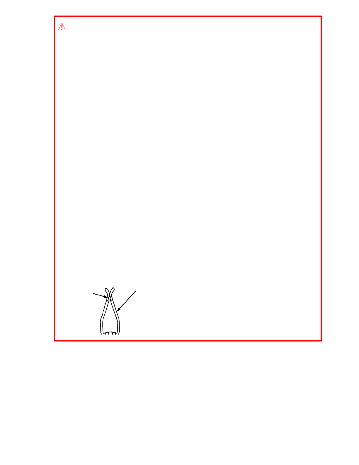
Worn Area
Worn Area
File Electrode
•
Replace the file electrode when it is worn to the
extent indicated in the illustration. It could
break if used after reaching this point.
( see page 26 )
Operation 12. 21. ’04

Page 4
PROHIBITION
•
Do not use this unit in conjunction with an electric scalpel or on patients who have a
pacemaker.
•
Do not use this unit in the medical operation room.
•
Blocked canals cannot be accurately measured.
•
This unit must not be connected to or used in combination with any other apparatus or
system. It must not be used as an integral component of any other apparatus or system.
J. Morita Mfg. Corp. will not be responsible for accidents, equipment damage, bodily
injury or any other trouble which results from ignoring this prohibition.
•
Illumination devices such as fluorescent lights and the Film viewer which use an inverter
can cause ROOT ZX II to operate erratically. Do not use ROOT ZX II near devices such
as these.
•
Electromagnetic wave interference could cause this unit to operate in an abnormal,
random and possibly dangerous manner. Cellular phone, transceivers, remote controls
and all other devices which transmit electromagnetic waves located inside the building
should be turned off.
Operation 12. 21. ’04
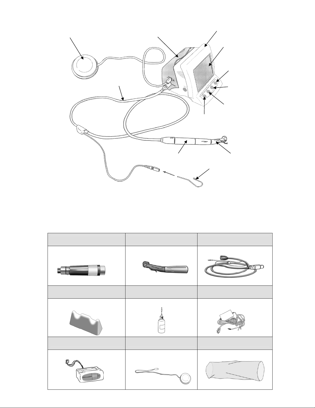
2. Parts Identification
Foot Switch
Low Speed Handpiece Module
Handpiece Cord
Micromotor
Page 5
Canal Measurement Module
(Sold separately)
Liquid Crystal Display
Set Switch
Select Switch
Mode Switch
Power Switch
Contra Angle
Contrary Electrode
(Canal Measurement
Module accessory)
* Low Speed Handpiece Module must be connected to Canal Measurement Module.
* Low Speed Handpiece Module cannot be used as an independent unit.
* In this manual, root canal measurement unit is called Canal Measurement Module and root
canal treatment unit is called Low Speed Handpiece Module.
Accessories
Micromotor (1) Contra Angle (1) Handpiece Cord (1)
TR800-Blue Line
TR400-Green Line (Option)
Handpiece Rest (1) AR Oil (1) AC Adapter (1)
Battery (1) Foot Switch (1) Plastic Sleeve (20)
(Pre-installed)
Operation 12. 21. ’04
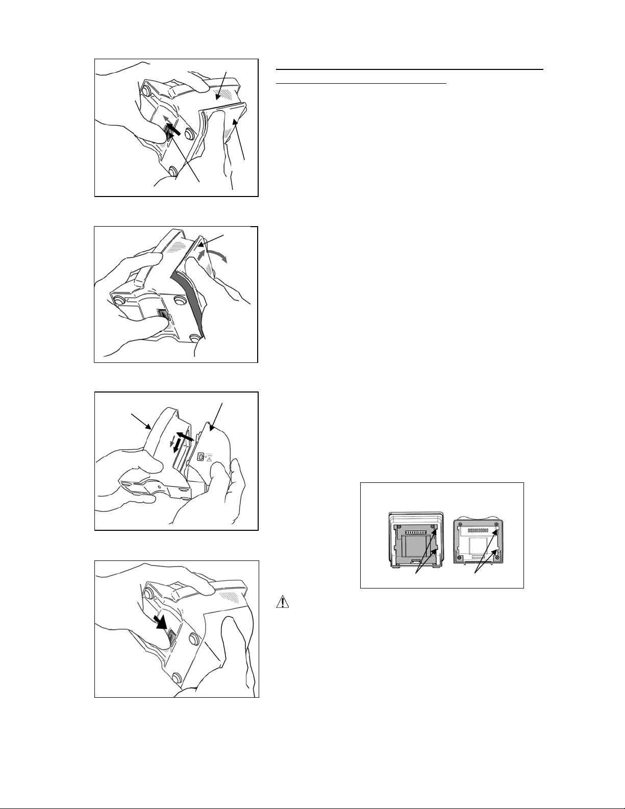
3. Assembling the Unit
p
Canal
Measurement
Module
Canal Measurement Module
Cover
Stopper
Cover
Low Speed Handpiece Module
Page 6
Attaching Low Speed Handpiece Module to
Canal Measurement Module
1. Hold the cover and slide the stopper on the bottom
towards the liquid crystal display.
2. Slide the cover in the direction indicated by the arrow in
the illustration and remove it from Canal Measurement
Module .
* The cover and batteries will not be used.
3. Line up the tabs on Low Speed Handpiece Module
with the notches in Canal Measurement Module and put
them together.
4. Slide Low Speed Handpiece Module all the way down
until it is securely attached.
Canal Measurement
Module
Low Speed
Hand
iece Module
NOTE
•
If the catch on the bottom is not back in its original
Notches
Tab s
place after attachment, push it in the direction shown
by the arrow in the illustration.
•
After installation, give Low Speed Handpiece Module
a light tug to confirm it is securely attached.
Operation 12. 21. ’04
Page 7
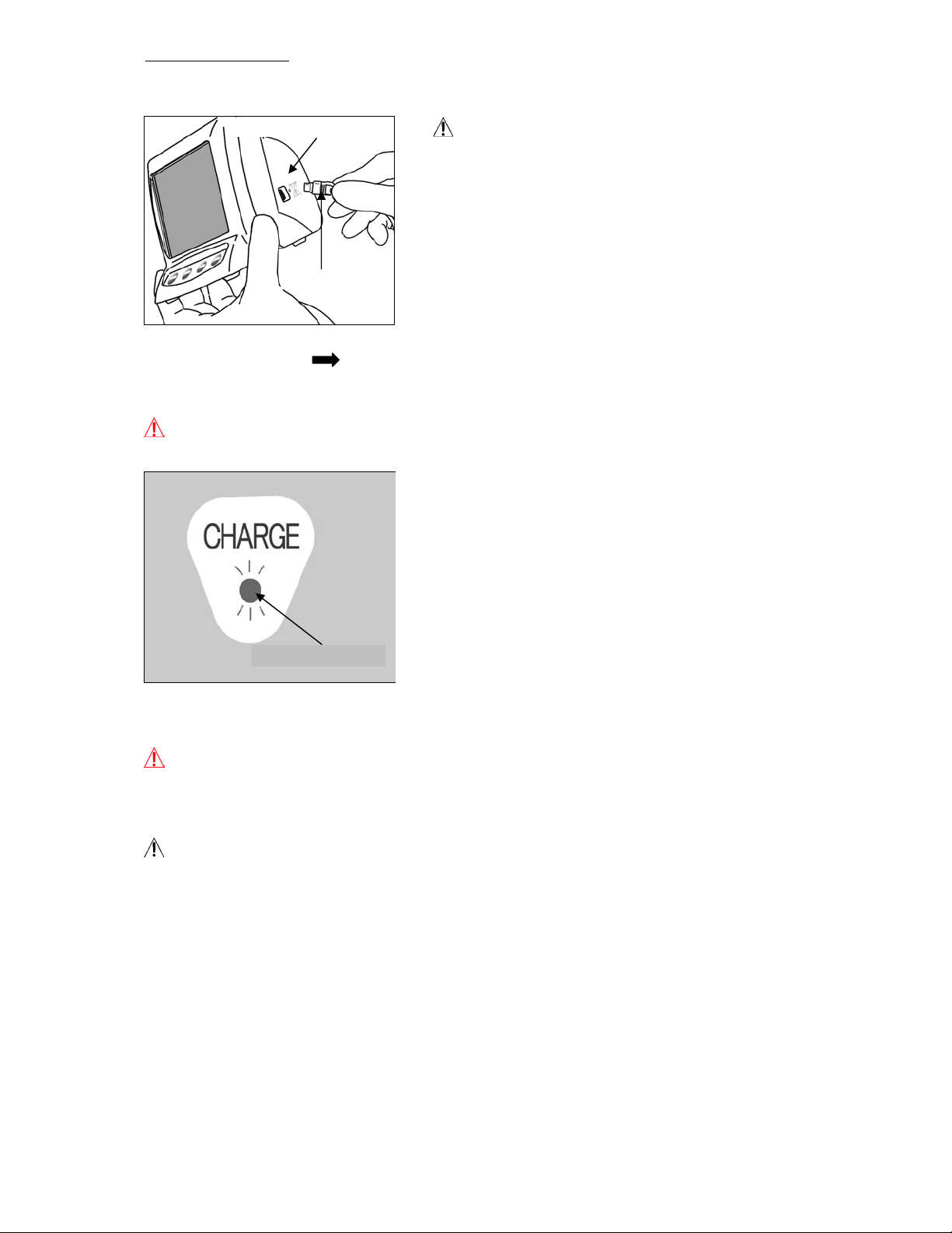
Charging Battery
The battery is built into Low Speed Handpiece Module.
Low Speed Handpiece Module
AC Adapter Plug
1. Line up the arrow ( ) on the AC adapter’s connector with the triangle ( ◀ ) above its jack on
the left side of Low Speed Handpiece Module and plug it in. Then plug the adapter into the
electrical power receptacle.
WARN ING
•
Do not use the unit when the AC adapter is connected.
NOTE
•
The battery is not charged when the unit is shipped
from the factory and must be charged before using
the unit.
•
If the plug for the AC adapter does not fit the socket,
it is the user’s responsibility to find a suitable plug
adapter.
2. The Amber Charge LED on the back of Low Speed
Handpiece Module starts flashing on and off and then,
after a few seconds, it will stop flashing and stay on to
show that the battery is being charged. It takes
about 60 minutes to fully charge the battery.
3. Amber Charge LED goes out when the battery is fully charged.
4. Disconnect the AC adapter from Low Speed Handpiece Module and unplug it.
WARN ING
•
Never operate the unit with an external power supply.
•
If an electrical storm occurs while the battery is being charged, do not touch the AC adapter or
the charger’s power supply cord as there would be a risk receiving an electric shock.
NOTE
•
Do not pull or yank the cord when disconnecting the AC adapter.
Amber Charge LED On
Operation 12. 21. ’04
4. Before Using the Unit
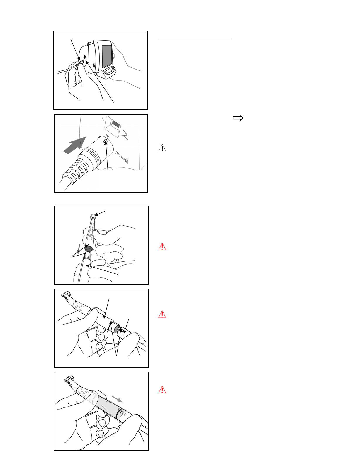
Handpiece Cord Plug
Page 8
Assembling Micromotor
* Contra angle must be lubricated with AR Oil before
using for the first time. Refer to “Lubricating the
Contra Angle” on page 25.
●Dots
Low Speed Handpiece Module
1. Line up the arrow ( ) on the handpiece cord
connector with the triangle (▼) above its jack on the left
side of Low Speed Handpiece Module and plug it in.
NOTE
•
Handle Low Speed Handpiece Module carefully; do not
drop, bump or expose it to other kinds of impacts or
Plug in until the tip of
the arrow reaches the
surface marked with
the small triangle (▼).
shocks. Rough handling could cause damage.
•
Make sure the plug is securely plugged into the jack.
A poor connection can cause malfunction.
•
Do not drop anything on or bang the plug after it has
been inserted into the jack.
Contra Angle
2. Line up the dots on the micromotor and contra angle
and slide the contra angle straight onto the micromotor
until it clicks securely into place. The contra angle has
a simple snap-on connection.
WARNING
•
After attaching contra angle to the micromotor, give
the micromotor a light tug to confirm it is securely
attached.
Micromotor
Micromotor
3. Line up the triangle (▼) to connect the micromotor to
handpiece cord.
Handpiece
Cord
WARNING
•
After attaching the micromotor to handpiece cord, give
the micromotor a light tug to confirm it is securely
attached.
▲Triangle Marks
4. Put a plastic sleeve on the micromotor portion.
WARNING
•
Plastic sleeves must be replaced after each patient.
Operation 12. 21. ’04
Page 9
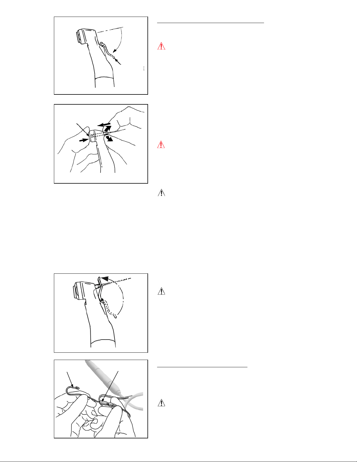
Assembling File and File Electrode
Use only nickel-titanium files for root canal preparation.
WARNING
•
Never use stretched, deformed or damaged files.
File Release Button
File Electrode
1. Gently pull back the file electrode.
2. Hold down the file release button on the contra angle
and insert the file. Turn the file back and forth until it
is lined up with interior latch groove and slips into place.
Release the button to lock the file into the contra angle.
WARNING
•
Give the file a light tug to confirm it is securely held in
place. If the file is not securely placed, it could come
out and injure the patient.
•
Take care to avoid the risk of a file being swallowed by
the patient.
NOTE
Use caution when inserting and removing files to
•
avoid injury to fingers.
•
Inserting and removing files without holding the file
release button may damage the chuck.
•
Do not attach the file electrode to files with a shaft
diameter of 1.2mm or greater, or large shafted tools
such as Largo bur. The file electrode cannot be
attached to files and Gates-Glidden reamers that do
not have circular shafts. Set the unit for manual
mode when using these types of instruments.
3. Gently clip the file electrode securely onto the file.
Contrary
Electrode
NOTE
Do not clip the file electrode to the cutting part of the
•
file.
•
The file electrode cannot be attached onto some files.
Connector
Attaching Contrary Electrode
Insert the contrary electrode (lip clip) into the connector of
the handpiece cord. (The contrary electrode is an accessory
provided with Canal Measurement Module.)
NOTE
Always hold the connector to connect or disconnect
•
cords.
Operation 12. 21. ’04
Page 10
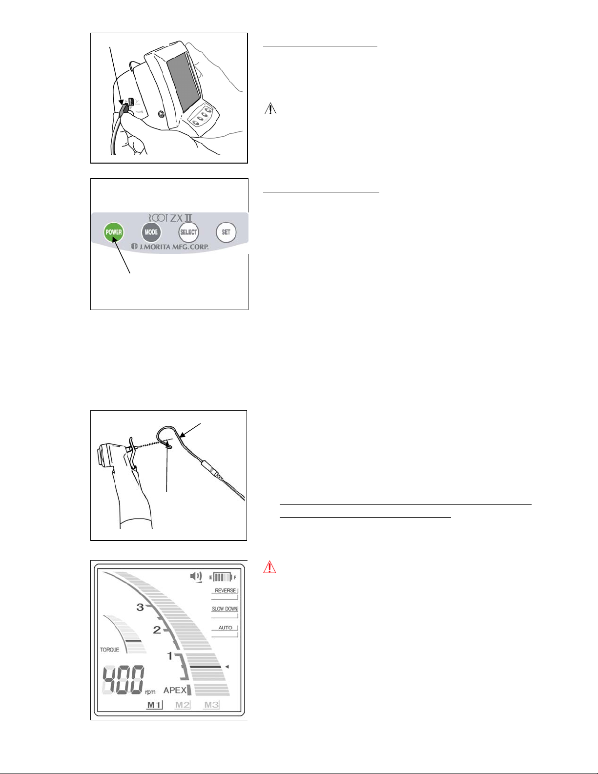
Foot Switch Plug
Power Switch
Attaching Foot Switch
Insert the foot switch plug all the way into its jack on the
left side of Low Speed Handpiece Module. [This jack is
marked with a triangle (▲) pointing up.]
NOTE
●
Always hold the connector to connect or disconnect
cords.
Checking the Function
1. Press the Power switch to turn the unit on. Display used
for root canal preparation will appear.
* The unit will automatically turn off after 5 minutes of
non-use.
2. Check that the handpiece cord is properly plugged into
the jack.
3. Check that the contra angle is securely attached to the
micromotor.
4. Check that the file is properly installed. Give it a light
tug to confirm.
5. Check that the file electrode is properly clipped onto the
file.
Contrary
Eelectrode
File Holder Contact
6. Check that the contrary electrode is attached to the
connector of the handpiece cord.
7. Contact the file with contrary electrode and check that
all the canal length indicator bars on the display are lit,
the word “APEX” flashes and audible beep becomes
continuous. Use caution when contacting the file with
contrary electrode as the file starts to rotate as soon as
the file touches the contrary electrode.
WARNING
●
Check the unit’s operation before each patient. If the
indicators in the display do not appear normally, the
unit may not be able to make an accurate
measurement. In this case, stop using the unit and
have it repaired.
Operation 12. 21. ’04
 Loading...