

Page 1
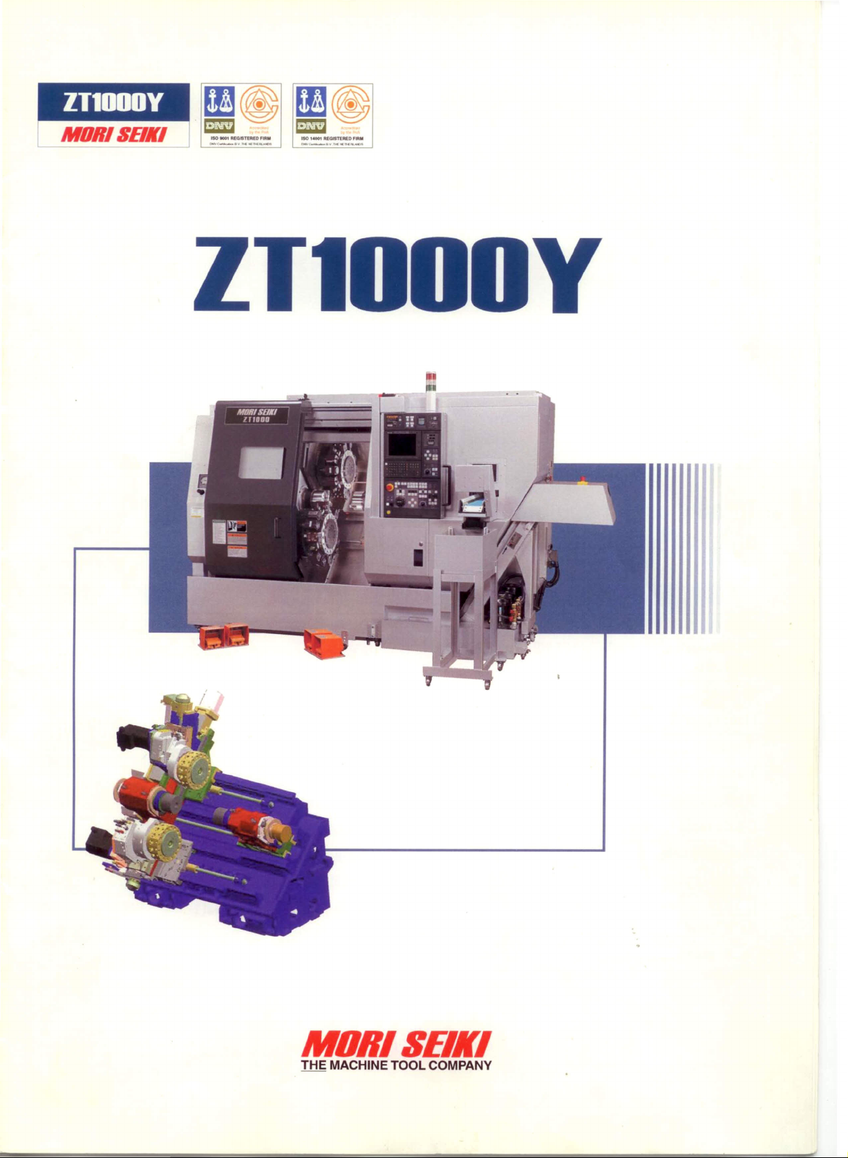
lTl000Y
MORI SElli
., ••• ~1nDlLDAUI 1:10,--.
_c-."......-__ _c- ....
1IIlGISTl1IIUI,....
M...-N ••.-
MORISElli
THE MACHINE TOOL COMPANV
Page 2
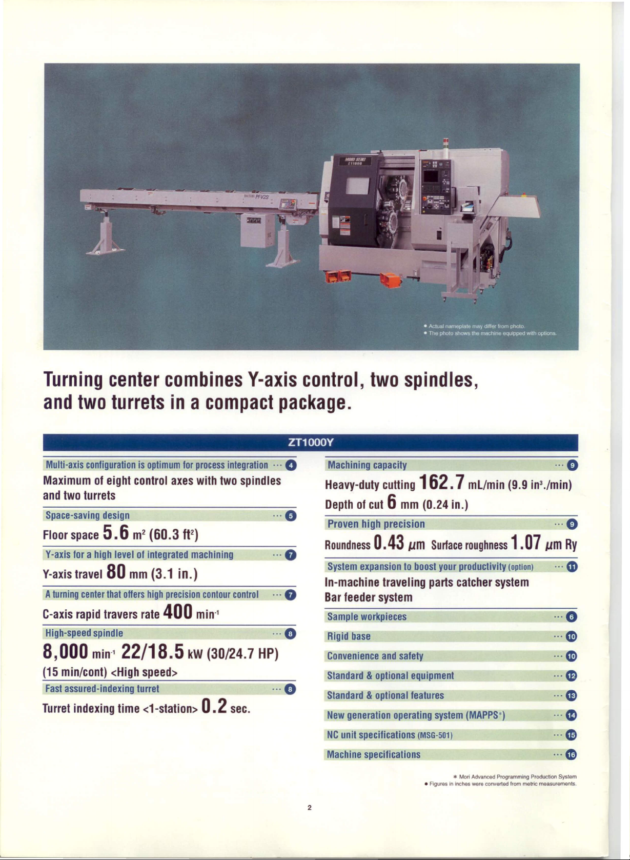
Turning center combines Y-axis control, two spindles,
and two turrets in a compact package.
ZT1000Y
Multi-axis configuration is optimum for process integration ...
Maximum01eight control axes with two spindles
and two turrets
Space-saving design ...
Floor space
Y-axis for a high level of integrated machining ...
Y-axis travel
Aturning centerthat offers high precision contour control ...
C-axis rapid travers rate
High-speed spindle ...
8,000
(15 mìn/com) <High
Fast assured-indexing turret ...
Turret indexing time et-statlon»
5.6
80
min·
2
m
(60.3 It
mm
(3.1 in.)
1
22/18.5
speens
2
)
400
mln'
kW (30/24.7 HP)
0.2
sec.
o
e
O
O
O
O
Machining capacity ...
Heavy-duty cutting
Depth01cut6mm (0.24 in.)
Proven high precision ...
Roundness
System expansion to boost your productivity
In-machine traveling parts catcher system
Bar leeder system
Sample workpieces
Rigid base
Convenience and safety
Standard&optional equipment
Standard&optional features
New generation operating system (MAPPS*)
NCunit specifications
Machine specifications ...
0.43
162.7
,.,m
Surface roughness
(MSG·501) •••
mL/min (9.9 in3./min)
1.07
(oplion) ...
,.,m
O
O
Ry
CD
O
O
O
G
eD
CD
CD
G
*
• Agures In inches were converted tram metrk: measurements.
2
Mori Advanced Programmlng Production System
Page 3
Laborsaving functions and a spindle configuration that are
ideai for integrating processes and lowering operation
costs.
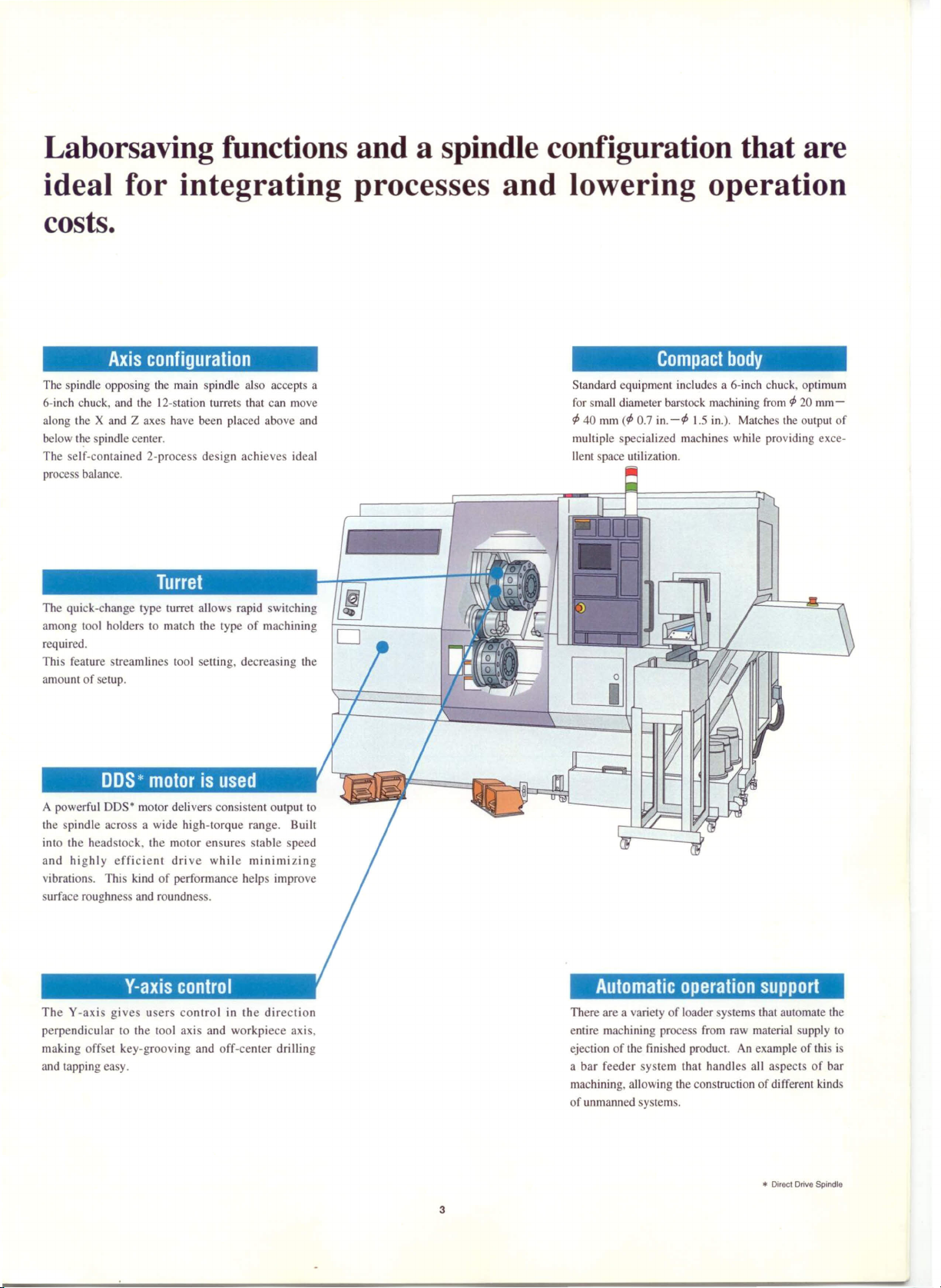
Axis configuration
The spindle oppo ing the main spindle al o accepts a
6-inch chuck, and the 12-station turret that can move
along the X and Z axes have been placed above and
below l~e spindle center.
The seI f-contained 2-process de ign achieves ideaI
proces balance.
lurret
The quick-change type turret allows rapid switching
among 1001 holders to match the type of machining
required.
Thi feature treamlines 1001 euing, decreasing the
amount of setup.
DDS*motor is used
A powerful DDS· motor delivers consistent output to
the spindle across a wide high-torque range. Built
into the headstock, the rnotor ensure stable peed
and highly efficient drive while minimizing
vibralions. This kind of performance helps improve
urface roughnes and roundnes .
Compact body
Standard equipment includes a 6-inch chuck, optimum
for small diameter barstock machining from<P20 mm+
<P
40 mm
(<p
0.7 in.
-<P
1.5 in.). Matches the output of
multiple specialized machines while providing exce-
llent space utilizalion.
o
The Y-axi gi ves users control in the direction
perpendicular lO the 1001 axi and workpiece axi ,
making off et key-grooving and off-center drilling
and tapping easy.
Automatic operation support
There are a variety of loader y tems that automate the
entire machining process from raw material supply to
ejection of the fini hed producI. An example of this i
a bar feeder ystem that handles ali a pects of bar
machining. allowing the construction of different kinds
of unmanned y tem .
*
Direct Orfva Spindle
3
Page 4
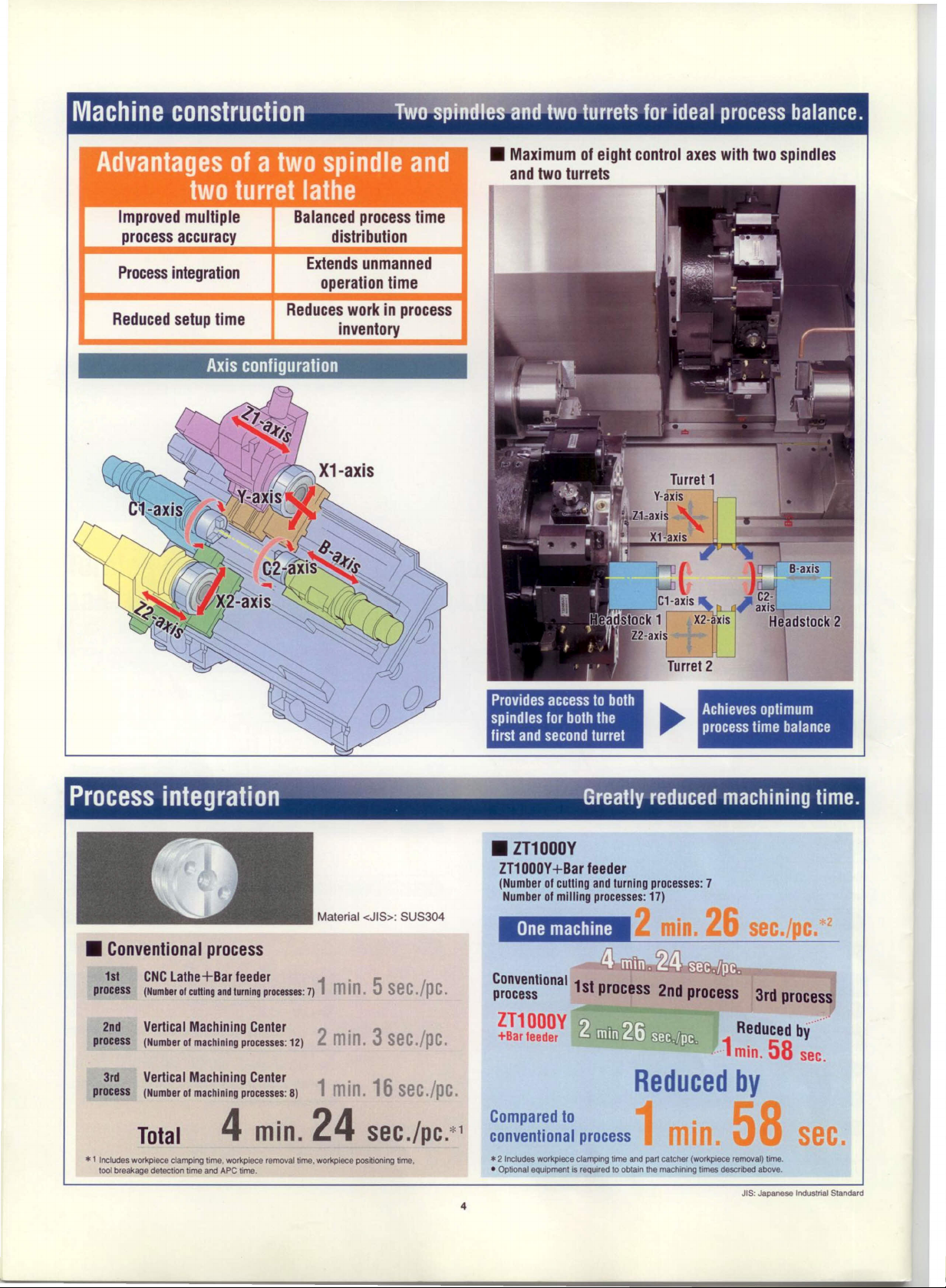
of a two spindle and
Improved multiple
process accuracy
turret lathe
Balanced process time
distribution
Processintegration
Reduced setup time
Axis configuration
Extends unmanned
operation time
Reduces work in process
inventory
Provides access lo bolh
spindles for bolh Ihe
first and second turret
Achieves optimum
process time balance
Material
<JIS>: SUS304
1s1 CNCLatha+Bar feeder
process (Number01cuttlngandlurningprocesses:7)
2nd Vertical Machining Center
process (Number 01machlnlng processes: 12)
3rd Vertical Machining Center
process (Numberolmachlnlngprocesses:8) 1
4
Total
• 1 Includes workptece clamping lime. workpiece removal lime. workpiece positioning tlme.
1001breakage detection lime and APe time.
min.
l'
mIn.5sec./pc.
2
min.3sec./pc.
min.16sec./pc.
24
sec./pc.*l
• ZT1000Y
ZT1OOOY+Bar feeder
(Number 01culling and turning processes: 7
Number 01milling processes: 17)
Onemachine
~~~::S~ional
1st process 2nd process 3rd process
ZT1000Y
+Bar leeder
Reduced
Compared to
conventional process
.2
Includes workplece clamping lime and part catcner (worl<plece removal) lime .
• Optional equipment is
4
reqUl1ed
lo obtain the machining limes descnbed above.
ec./pc.
Reducedby······
·1
min.
58
sec.
by
sec.
JIS: Japanese Industriai Standard
"'2
Page 5
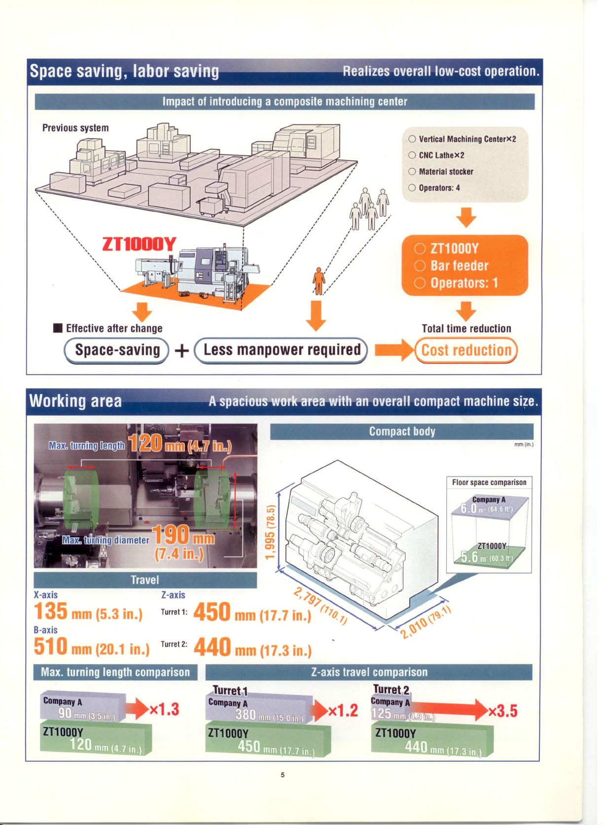
Space saving, labor saving'-Rèalizes overalllow-cosioperalion.
Impact01introducing a composite machining center
o
Vertical Machining Centerx2
o
CNClathex2
o
Material stocker
O
,
,
,
,
,
,
,
,
,
,
,
,
,
,
,
,
,
,
,
,
,
,
,
,
,
,
,
,
,
,
-,
Operators: 4
o
ZT1000Y
O
Barfeeder
O
Operalors:
•
1
• Effective after change
•
Space-saving
+
Less manpower required
Total time reduction
•
Cosl reduclion
Working area -':~òverall compaclmachinesìze.
Compact body
mm(ln.)
Floor space comparison
Travel
X-axis
135
B-axis
mm
(5.3
in.)
Z-axis
Turre! 1:
450
mm
(17.7
<';>9;>
in.)
(77Q lJ
510
Max. turning length comparison
mm
(20.1
in.)
Turre!2:
440
ZT1000Y
mm
j ,
(17.3
5
in.)
Z-axis travel comparison
Page 6

Sample workpieces .
• Sample workpiece machined with the ZT1000Y
~k
al whal precision machining can do.
Sample workpiece with Y-axis control
Sample workpiece with Y-axis control
Sample workpiece with Y-axis control
Sample workpiece with Y-axis control
6
Page 7

Y-axis control
_otary toolsforintegratedmachining.
l7
-aXis '---
-...-..,--::.=-----'
Largest of ali o e
Y-axis travellathes
mm
Y-axis machining range
Spindle cantar
(2.0)
50
(3.
in.)
3S 75
(1.4) (3.0)
mm(in.)
• Circurnferentialgroovingon a turningcenter with Y·axis
Milling without
It is hard to match the width of
outer (a) and inner (b) grooves.
~
Y-axis
b
control
Milling on the ZT1000Y
Groove width can be matched
•
using Y-axis control.
contro
• Comparison between polar coordinate interpolation
and Y-axis control
On a conventional turning center, polar coordinate interpolation is used for tool
motion control during grooving and contouring, as illustrated in the left figure.
In this control mode, however, the X-axis travel direction is reversed at points
"a", the intersections between the workpiece center line and the profile to be
machined. This reversal changes cutting conditions and subsequently effects
profile accuracy. Machining with v-axìs control, on the other hand, is Iree of
such changes and ensures a high level 01profile accuracy.
X·ax~
(-)
I
• Points -0-, inlerseclions belWeeo the wor!<piace center ine ard the prome IObe
C-axis rapid travers rate
Polar coordinate interpolation
Y-axìs control
machined.
C·axis exchangingtime
0.52 sec.
Milling is possible during spindle rotation. High preci-
sion contour control is delivered Irom a DDS· motor
acting as the c-axìs indexing servo.
(The pholo shows
*
Direct Drive Spindle
• The cutting test results indlcated in thls catalog are provided as an example. The results indicated In this catalog may not be
ZT2500Y.)
7
0.54 sec.
0.56 sec.
cotalned
due to differences in cutting conditions and environmental conditions durlng measurement.
Page 8

Spindle
'-~;-'a~e specificationsfor bothspindles.
High-output spindle for machining
diverse types of workpieces.
• For5-/6-inch chuck
• Through spindle holediameler49mm
(1.9
in.)
• Headstock 1
• Headstock 2
Oil cooler included as standard equiprnent
• Both spindles (headslock 1 spindle and headslock
2
spindle) are wrapped in an oil jackel lo minimize
I~
Di!
jacket
011
cooler
• Headstock 1 shown here.
11/7.5 kW (15/10 HP)
6,000 min·
1
<10 min/30 mln/cunt»
• I. 1
6,000
mln
100 .
80· . .
~ 60 TaS5.2N·m4Q.7ft· <ooob
~ 40 •.421 N'm 31.1h' <3OmJn>
30 T:3IJ9N'm 22.8fHb
{!
~
2O~----h~'+-
7.5/5.5 kW (10/7.5 HP)
<30 min/conl>
>
<CXlI'Ib
0433ISAOl
l'' I
8,000 min'l 22/18.5 kW (30/24.7 HP)
<15 min/cnnt»
~r-----.--==~~
=r-----t--~~~
E1100
~ Tz:42
N'm
f!
40
~ 5O~'~5~min~>~~~~~~~;E
(:!.
30 T-:35N'm
20 ~~~'lbf,L....,.4L-+---;........c>~
(31.0 tt-tbt)
04331'801
• Oplion
• Quick-change type turret head
(VOI)
O,
'.
,
Oual lurrets come standard including a quick-change type
turret for VOI tools. This draslically shorlens
lime.
(The photo snows ts-toot specification.)
1001
change
Indexing time
(1-station)
Number of tool stations
0.2 sec.
32
(16+16)*
t
I
(turret 1+2) 00 S
=
Opticn
• Bolt-tightened turret head
(option)
3.7/2.2 kW (5/3 HP)
6,000 min'
l
<15 mln/eunt»
40t~=;;;~=.:;;==tA3=.7=kW=<='5~m=1ln>
rl:
=23.5
N'm
17.3ft'lbf : 2.2
i
=14N'm (10.3fHbf); S
g
con :
>-
IO [
5
100
Rotary tool spindle
speed
(mio
kW
l)
<COnI> :
043S11AOl
4
§'~
S
,O
8
Page 9

Processing speed
~'''''--';rl~rmance
in ali machining ranges.
Tapping (O.D.): M12XP1.75
Material <JIS> S45C"
Rotarytool 398 min
spindle speed
Feedrate 1.75 mm/rev (0.069 ipr)
Cutting speed 15 m/min (49.2 fpm)
Drilling
Material <JIS> S45C"
R~tarytool 612 rnln'
spindle
speed
Cutting speed 25 m/mln (82.0 fpm)
Feedrate 0.24 mm/rev (0.009 ipr)
Machining rate 19.5 mUmin
per minute (1.2 in'Jmin)
End mill
Material <JIS> S45C"
R~tarytool 530 min
splndle
speed
Cutting speed 20 m/min (65.6 fpm)
Feedrate 0.2 mm/rev (0.008 ipr)
Machlning rate 12.7 mUmin
per minute (0.8 in'.!min)
Throw-away drill
Heavy-duty cutting
• Headstock 1, Turret 1
I
Making fuI! use of the high output DDS" motor, heavy-duty 0.0. cutting is powerful and
precise evenwilh large workpieces.
Machining rate per minute
162.7
(9.9
i 3./min)
Depth 01 cut
6
mm
Material<JIS> S45C"
Outerdiameter
Cutting speed
Feedrate
I
• Headstock 1
Turrels 1 and 2 move synchronously in 0.0. cutting lo ensure high precision balanced
cutting.
Balanced cutting
mUmin
(0.24
in.)
80 mm (3.1in.)
120 m/min (393.7 fpm)
0.2 mm/rev (0.008 ipr)
High precision
lO
jJm
/
-----
Tool
Material
Outerdlameter
Spindlespeed
Feedrate 0.05 mm/rev (0.002 ipr)
Diamondtool
enose
Brass
40mm(1.6 in.)
1,000 rnìrr
(filter:
radius0.4mm (0.02
Material<JIS> S45C"
Spindlespeed 1,091 min
Cutting speed 120 m/min (393.7fpm)
Feedrate 0.22 mm/rev (0.009 ipr)
Machining rate230.9 mUmin
per minute (14.1 in'Jmin)
I
*
l Carbon steel
*2 Dlrect D,lvo Splndlo
~-precision
1-50)
Roundness
ln.)
0.43
l'm
Turning precision
(/.lm
2.0
r:...
l=j...+=..+t..+ ..+t.+. '+'f'+' .=+..!,=I.. =i...j=1...IH=...j...,I=..f;::::... I=..+,..+=..+f..
0.0~·1tI.·.~.~.
-1"''T' .....
j
-2.0 ..
..
-+-+.-+-
Tool
Material
Outerdiameter 40mm(1.6 in.)
Splndlespeed
Feedrate
'M"'~"~"~~'
"'1
'i"
Diamond tool
enoseradius0.4 mm (0.02in.»
Brass
3,000 min
0.05 mm/rev (0.002 ipr)
~''-R'~~'~.~.
"'T-~~4:'
T'
,or
-1---+-t'. ~- ..~...
I
'T"'T"-r"'r'
JIS: Japanose Induslrial Standard
can be seen in the data.
+...
+.t +...+++... +-+=1.. =i,.t=1.. ::J.ff=.. I=...l=f.. +=...l=f._+..++.+..+.j +... +1+_
~'-~·~~M.iOO·
'"i"o
-j- T
-t' ••
-+..
+..
'--l-'
+-.+
"i"o
T-
.+- .--i-.
M.J,~.,.;.l,'"
oO
Surface roughness
1.07
lIm
Ry
O":
.y
4.0mm
(0.02
in.)
• The cutUng test resutts indicated in thlS cataJog SfO prov;ded as an example. The results indicated in this catalog may noi be obtained due to differenoos in cutting conditions and environmental condrtions during measurement
9
Page 10

High rigidity is ensured with slideways.
Ribbing was optimized by FEM' analysis.
*
Finite Elamenl Method
• Carefully designed ribbing
Achieves excellent chip removal by using a
45° slant construction.
Operability, Safety
Adjustable
operating panel
Swinging the operation panel reduces
eyestrain and improves operability.
device~rgonornic
Built for safety
Door interlock system
Footswitch with lock device Chuck jaw stroke end
e
Full covereCylinder check valve"eLow air pressure detecting switch
e
Low hydraulic pressure detecting switch
e
Danger sensing device interlace
e
Earth leakage breaker(opllon)eWorkpiece holding detector(option}
.1 Featured only when optional
*
2 Recommended whon
chucklcylinderIsselected.
oìt-based
coolanlls used or durlng unmanned operatlon.
Impact resistant viewing window Smaller maintenance area since the coolant
check-
'2
(optlon)
operating environrnent.
Operability
tanks both pull lorward, thereby allowing a
shorter right-side pull-out distance.
High maintainability
Allows the lubricating oillevel to be checked
at one glance by opening the cover 01 the
control pane!.
10
Page 11

Extended unrnanned
oper~"
Unmanned systems for
need greater efflclency.
us~r~
who
In-machine traveling parts catcher system
Parts catcher can receive workpieces trom both spindles. And,
unmanned operation is possible when coupled with a workpiece trans-
porting
conveyor.
• Receiver type
Headstock 1 side
(The p~oto shows ZT2500Y.)
In-machine traveling
Hand model
Max. transler weighl 1.2 kg (2.6Ib.)
Max. speed<Z-axis>
Applicable
workpiece
Ouler diameler
Lenglh 20-120 mm (0.8-4.7 in.)
parts catcher
Recelver typeISingle-hand
40 mm (1.6 in.)
specificalion
100 m/min (328.1 fpm)
10-40 mm
I
(0.4-1.6 in.)
type
• Single-hand type
~
----
(option)
In-machine traveling parts catcher (receiver type)
Workpiece transporting conveyor
Bar feeder system
Complele bar machining is possible on a single machine when coupled with
a parts catcher. You won't needa work loader/unloader or
• Recommended accessories
for bar feeder specification
• Bar feeder
• Signal tower
• Work stopper
• Multi counter
• Guide bushing
turnover
unit.
(option)
In-machine traveling parts catcher
(receiver type)
/
Workpiece transporting
conveyor
Slandard fealures
Toollife management lunction B (monitor)
Load monitoring function (monitor)
Work counter (monitor)
Total counter (monitor)
Optional fealures
Work counter
Tolal counler
x1.2
CompanyB
x1.1
*
Depending on tha chucklcylinder used and Il'5 restrlctions, il may noi be posslble lo reach
lun
bar work capacity.
11
Page 12

I
Standard&optional equipment
Automatic
operation support
o
Coolant
Spindle
Safetv features
Operation support
device/function
Turret 2
Collet chuck
Chip disposal, Automatic operation support
• Chip
Oil mist collector
*
Chip
conveyor
conveyors are
Tool presetter
(eptlcn)"
avallable in various types lor handllng chips of dlNerent shape and materìar.
• Far details contact Mori
Guide bushing
Guide bushing
Sand.
[ 5 3 I
Yr:'
(r--
ç,--
-
~Rr--' ,....--.
Work counter
~r
Chuck air blow
Dii skimmer
• The cotors and configuration shown in the photographs may differ 'rom Ihose of Ihe aclual product.
12
Coolant float switch
Page 13

Standard & optional features
e:
Standard features
Spindle Improved accuracy
Max. spindle speed eheadstock 1>
Max. spindle speed eneadstock 2>
Dii cooler
Spindle orientation
Turret
Quick-change type turret head
Bolt-tightened turret head
Max. rotary tool spindle speed 6,000 rnln: <3.7/2.2 kW (513HP)">
Workpiece holding device
Hydraulic chuck
Collet chuck
Chuck higMow pressure system
Index chuck eheadstock 1>
Soft jaws
Coolant
Coolant system
High-pressure coolant system
Coolant cooling unit
Coolant floal switch
011
sklmmer
Automal/c operal/on support
In-machlne traveling pans catcner
Workpiece transporting conveyor
Workpiece bucket
Workpiece push-out equipmenl
Work pusher
Bar leeder
Gantry-type loader
Work stocker
Pull-out finger
Guide bushing
Work stopper
Operal/on support device/funcl/on
Work counter
Total counter
Multi counter
Automatic door
Automatic power
011
system
6,000min' <7.515.5kW
6,000 min' <11fl.5 kW (15/10HP)">
8,000min"<22/18.5kW(30/24.7HP)">
6,000min' <7.515.5kW
6,000 min' <11fl.5 kW (15/10HP)">
8,000min' <22/18.5kW(30124.7HP)">
12-station cshank diameter
25 mm (1 ìn.)
16-station cshank diameter
25 mm (1 ìn.)
12-station <metric speciticatlons
16-station <metri c specììlcatlor»
12-slation «ncn specìfìcatior»
16-station cinch specificaìior»
5-inch eheadstock 1>
6-inch cheadstock 1>
5-inch eneadstock 2>
6-inch eheadstock 2>
Nominai diameler 40 mm (1.6 in.)
Interface 0.75 kW (1 HP)
Interface 1.5 kW (2 HP)
325/520 W <50/60 Hz>
635/1,040 W <50/60 Hz>
Receiver
Single-hand type
(1017.5
(1017.5
HP)">
HP)">
O
O
O
O
O
O
O
O
O
•
O
O
-(:
O
O
O
O
O
O
-((
O
-((
-(:
-((
-(:
O
O
O
*
O
O
•
o
-tt
•
O
-tt
•
O
•
O
-(:
-(:
-(:
-(:
•
o:
Options
*:
Please contact Mori Seiki
Direct scale leedback
Measurement
Automatic measuring system Dptical touch sensor
Manualtype in-machinetool presetter
Automatic in-machine tool preselter
Chip disposal
Chip conveyor coutsìde rnachìnes
Chip removable coolant system-
Alr blow system In-machine tool presetter
Chip bucket
Coolant gun
Oil mìst collector
Others
Built-in worklight
T
001
holders
Hand tools
Signaltower 3-stage
Chuck
1001
switch
Work stop per <in spindles
Safety features
Door inlerlock system
Impact resistant viewing window
Chuck jaw stroke end cneck-
Low hydraulic pressure detecting switch
Footswitch wlth lock device
Full cover
Cylinder cneck valve"
Low aìr pressure detecting switch
Danger sensing device interface"
Earth leakage breaker
Workpiece holding detector
• 130minlconl
.2
15 minlconl
• 3 For
rear
extIaction
.4
Headslock2is standard.
.5 Featured only when optional
• 6 Recommended when
• The det811s given abava and lhe spec:dications are subject lo change Wlthout
• Specirlcations.
• Some options are noi available in particutar regions. For details contact Moti Seiki.
accessories,
type chip conveyor.
chucklcytinderisselected.
ca-besee coolant
safety device. 800 function
G-axis
x-axìs
Y-axis
Z-axis
Removable
Hinge type <righI>
Seraper type <righI>
Hlnge type
crear»
Scraper type
Interface
Chuck" eheadstock 1>
Tool tip
2 loot switches
RighI extraclion s1yteis optional.
is used or dunng unmanned operation.
crear»
are avallable
upon
notee.
request.
o
o
O
O
O
•
-(:
O
-(:
O
-(:
-(:
•
O
-(:
-(:
O
O
-(:
•
•
•
O
O
-(:
•
•
•
•
•
•
•
•
O
O
-(:
13
Page 14

N
ew gene rati on op erati n
irsyStemriVi~pps~r\"~'~'
• Conversationalautomaticprogramming
By inputting the linal shape 01the workpiece, the
MAPPS can automatically select the necessary
tools, cutting conditions and the most efficient
machining sequence, thus minimizing the amount
01input.
• Program editing
.
~ :llfi.m-cu2
io,
rJnl4:.:
,. t.t •••.• ,,,,",
J :
Two programs can be opened at the same ti me
and data copied&pasted between thern.
04321 N00000
",
.••.
01111
0,
r:,
rFII(t):
1t:!02'
'-,
Sl3l1G
klK..n.
ti:
~l•. r.25 :
i.e r.n .
XIM.U:
'.:tU;
l"! Il' I • "\
~~[
• Simulation
OUI. ~'lItI
j"lnn
""
..
r.l...••#1J'
'''\/LtLl
..•.
tu·!It.~
QIl!l.Z*'l
...
A simulated image 01 the machining workpiece
can be displayed to check proçrarnrnlnp.v
• Network
(oplion)
*
1 Mori Advanced Programmlng Production system*2 Some machinlng programs cannot be graphically simulated.
ConversationalAutomatic ProgrammiiffilS~pjo~l~two-turret Turning Centers
CAPS-ZT
• Automatic programming software
Supports complex multi-axis programming,
such as turning, C-axis and Y-axis machining,
sub-spindles, and balance cutting,
Y-axìs machining menu
• Detailed setup possible
(option)
-------]t'
PC·'
• 2 turrets machining
requiremenls
lIem Requlrement
PCIAT compatible
OOSN
Pentium'm1 GHz or more
NC processor
SVGA
128 MB or more
50 Ma or more avaliable area requlred
Wlndows' 95/98/Me/NT 4,0 Wor1<stationl
2000 ProfessionaliXP
CD-ROM drlve,
Paraliel pori D-SUa 25 pin", Serial port
.,.. , t~
e
~, • 1.1111 $U
'l'CI~~~
:uo .nUII,"U."
oIoJ"..lfuu.r •••.II.1
...."nu'\<l.o' •••
".:.t,
41aO_IU; :n
"
Jao. _
_ .••,U.I':'
_lI:l\1Ct.r:U.IIIlJ.·
;::l:!I:' I!:I
\ti':.
I ••
Easy creation 01 programs tor balance cutting and syn-
chronizing the No, 1 and No, 2 turrets.
Hardware
CPU
Graphics
Memory
Hard dlsk
OIS
Other
(min. 800X600 resolution and 65,536 colors)
J
-------1
--------------- ----o-or
------
~
-------l\
Bydelayingthe position where the cutting
begins,we doubled the amount 01material cut.
By synchronizing tool movement, we
raised the amount 01teed.
14
*
1 Personal Computer
*
2 USB
conversion
• The producI names indicated In this catalog are ali trademarks or registered
trademarks of tha individuai companies.
ls not posslble .
Page 15

Ne
unit specifications
(MSG-501)
Standard
Controlled axes
Controlled axes
Simultaneously controllable axes
Least tnput increment 0.001 mm (0.0001 In.)
Least command Increment
Max. command valua
InctVmetric converslon G20/G21
Inlerlock·'
Machine lock
Emergency stop
Stored stroke IImlt 1
Programmable mlrror lmage
FOllow-UP
Chamfering ON/OFF
Backlash compensation ±9.999
Rapld traverse/cuttlng feed backlash compensation
Stored pitch error compensation
Abnormalload detectlon
Cutling feedrate
Operallon
Search function
Manual intervenlionlrBturn
Dry run
Singie block
Jog feedrate 0-1,260 mmlmln (0-50.0 Ipm) <15 stepss
Manual zero return
Zero polnt setting without dog
Manual pulse handle leed
Interpotation funcllons
Posltioning GOO(Llnear Interpolatlon type positloning Is possible)
Llnear Interpolation
Circular Interpolation G02/G03
Dwell
Polar coordinate Interpolatlon G12.1, G13.1 (Gl12, G113)
Cylindrlcallnterpolation G7.1 (Gl07)
Helical interpolation
Thread culling/Synchronous leed
Multl-start thread culling
Retraet during thread cUlling cycle
Continuous thread cunìnç
Sklp G31
Zero retum G28
Zero retum check G27
2nd zero retum
Balance cut
Feed functlons
Rapid traverse rate override FO.25/100
Feedper minute G98
Feedper revolution
Constant tangenllal velocity control
Cutting feedrate cìamp
Feedrateoverride 0- t 50%(lO%increments)
Jog feedrate override
Overrlde cancel M48, M49
Program Input
Tape code EIA RS244/1S0 840 code automatic recognHion
Label sklp
Optional block skip 1 block
Max. command value ±8 digits
Program number
sequence number 5-dlgit N code
Absolute (incrementai) programmlng
Decimai polnt programmlng/
Eleetrical calculator type decimai point programming
Piane seleetlon
Coordinate system selting
Work coordinate system G52, GS3. G54-G59
Manual absolute onloff PCparameter
Drawlng dimenslon dlrectlnput
sua-prouram cali Up to 4 nestlngs
Single repetitive cycle
Multiple repetmve cycle
Multiple repetitive cycle il Pocket profile, zigzag thread culting
Hole machlnlng canned cycle
Circular arc radlus command
F15 format
H 1: X, Z,c,Y H 2: X, Z, C, B
H 1: X. Z. C.Y H2: X. Z.
0.001 mm (0.0001 In.)
±99,999.999 mm (±9,999.9999 in.)
M code
pulses
Used for sottware damper and load monitor B
Workpiece number, seqeence number
1 unit per control systern:
G01
(CW/CCW)
G04
G30
%
G99
0-1.260 mmlmln (0-50.0 Ipm)
4-dlgit Ocode
x
(U), Z (W), Y (V), C (H)
Electrical calculator type decimai polnt programming is
changeable using parameter
G17, G18, G19
G50
c
xt.xto.xioo
Miscellaneous funcllon/Splndle speed funcllon
Miscellaneous funetlon
Auxillary lunetlon lock
Spindle
speed
Constant surface speed control
Spindle speed override 50 120 % (10% Increments)
Synchronlzed tapping
Splndle synchronlzed control
Tool function/Tool ottset funcllon
Tool funetlon (T function)
Number 01tool offsets 64+64 sets
Tool posltlon offset
Y-axls onset
Tool nose radius otìset G40-G42
ToOIgeometry onseVTool wear onset
Toollile management B
Ediling
Part program storage 80+80 m (262+262 h) <4kB':"10 m (33 ") in tape length>
Number 01stored programs 63+63 programs
Tape editing
Program protect
Background editing
Expanded tape edlting
Selling and dlsplay
Status display
Clock lunetion
Actual posltion display
Program dlsplay
Parameter selting display
Sen-diagnosls funetlon
Alarm display
Afarm history display
Operator's message hlstory display
Running time display/NO. of parts dlsplay
Actual leedrate display
Display 01 actual spindle speed and T code
Operation panel: Display section 10.4-inch TFTcolor LCD
Data fnpul/Output
Reader/puncher Interface
lunetlon
3-digit M code
S-dlgit S code
Wlth rotary tool splndle
4-dlgit T code
Program name: 48 characters
Page 16

Machine specifications
lIem
Max. swing of workpiece mm(in.)
Max. distance betweencenters mm(in.) 750 (29.5)
Capaclty
Max. turning diameter mm(in.)
Standard turning diameter
Max. turning length mm(in.) 120 (4.7)
Bar work capacity°'
X-axis travel mm(ln.) NO.1: 135 (5.3) NO.2: 135 (5.3)
Travel
Z-axls travel mm(in.)
Y-axis travel mm(in.)
Headstock 2 travel <B-axls> mm(in.) 510 (20.1)
Spindle speed rangeo,
Number of spindle speed ranges 1
Splndle
Type of spindle nose
Through spindle holediameter mm(in.)
Spindle bearing inner dlameter mm(in.) 80 (3.1)
Min. spindle indexing angle 0.0010eleast input incremenl>
Number of tool stations 12 [16J
Shank height far square tool
Turrel
Shank diameter far boring bar mm (in.) 25 (1)
Turret Indexing lime
Max. rotary tool spindle speedo,
Feedrale
Rapidtraverse rate
Jog feedrate mm/min (Ipm)
Spindle drive motor <30 min/conl> kW(HP)
Molor
Rotary tool spindle drive motor <15 min/cont> kW(HP) 3.7/2.2 (5/3)
Feedmotor <X1/X2/Z1/Z2/Y!B>
Coolant pump motor
Power sources
Tank capacily
Machine size
Electrical power supplyoJ
Compressed air supply MPa (psi), Umin (gpm)
Coolant lank capacity
Machine height <lrom
nooo
Floor space cchip conveyor not Included> mm(ln.)
Mass of machlne
I l Option
NO.1: Turrel I NO.2: Turrel 2 JIS: Japanese Induslnal Siandard
*
1
Depending on
• 2 Depending on restrictions imposed by lha workplece clamplng
• 3 LoaderlParts cetcner
*
4 AI
*
5 15
.6 Hlgh-output specifications for headstock 1
*
7 High-speed specif)eations far headstock 1 and headstock 2.
• 8 ANR refers to a standard atmospheric state:i.e., temperature al 20t(68 •
8,000
minlcont
min'
tha
chucklcylinder
used and It's resmctlons, il may not be
noI Included.
The
eectrcer
and headstock 2.
power
devce.
reculrements
fixture and tool used, Il may noI be possible lo rotate al tha maximum spindla speed .
vary depending on tha opnoo comblnat!ons.
.
possible
F); absokne
to reach full bar
work capacity .
pressure a1101.3 kPa (14.7
ZT1000Y
250 (9.8) <iRterferencewith turret
190 (7.4)
mm(in.) 170 (6.6)
mm(in.) 40 (1.5)
No. 1: 450 (17.7) NO.2: 440 (17.3)
±40 (±1.6)
mirr
60-6,000 [80-8,ooOJ
JIS A2-5
49 (1.9)
mm(in.)
minI
mm/min (ipm)
s
X1, X2: 18,000 (708.7) Z1, Z2: 24,000 (944.9) Y: 6,000 (236.2)
B: 24,000 (944.9) C: 400 min'
20
0.2
6,000
X, Z, B: 0-1,260 (0-50.0)
7.515.5(10n.5)
[11n.5 (1511O)J[22/18.5 (30/24.7)0"'J
kW(HP) 3/2/3/3/1.5/3 (412.7/4/4/2/4)
kW(HP) 0.52x2 (0.70X2)
kVA 46.0 [52.7"l[92.7 o'J
0.5 (72.5), 100 (26.4) <ANR°,>
L (gai.)
mm(in.)
200 (52.8)
1,995 (78.5)
2,797x2,010 (110.1
kg (Ib.) 5,000 (11,000)
psì): and
relative humk1ìty at 65
%.
(3/.)
X79.1)
coveo
.
.
--
I
194215A02
--
-
-
!
• The information In Ihls catalog Is valid as of August 2002. Deslgn and specifications subject lo ehange Wlthout notlce.
• MOri Seiklls not
responsiote
for differences between tha Information in tbe eatalog and tha aetual maehlne.
MORI SEIKI CO., LTD.
Head Office&Nera Pian'
D .362 ldono-cho. Yamato-Konyama CII)'. Naro 6:\9-11 IO, Japan
Nara No.2 O 106 KIIIl Kortynma-cho. Ynrnato-Konyama eh)'. Naro 6:\9·1160. Japan
Plonl l'hone: (0743) 53-1125
lga Piani O 20) Midal. lga-cho. Ayama-gun, Milo! 519-1-1)-1. Japan
• The export of
Check Wllh the governmenl agency tor authorization.
Phonc: (074~) 53-1121
l'hom: (11595) 45-4151
this prodoct is
subject lo an aulhonzation 'rom the governmenl of the exporting country.
www.moriseiki.com
ZTHJQOY ·EBOl
0209 CDr 0000
Crealed in Japan
 Loading...