

Page 1

PROGRAMMING MANUAL
Applicable Model
SL-150, 150MC, 150Y
SL-150S, 150SMC, 150SY
SL-200, 200MC
SL-200S, 200SMC
SL-250, 250MC
SL-250S, 250SMC
SL-303, 303MC, 303Y
SL-400, 400MC
SL-600, 600MC
SL-25E
SL-65, 65MC
SL-75, 75MC
TL-40, 40MC, 40Y
VL-25
VL-55, 55MC
LL-7, 8
CL1500, 1500T
CL2000, 2000T
Applicable NC Unit
MSC-500 MSD-501
MSC-501 MSD-518
MSC-518 MSD-501II
MSG-501 MSD-518II
Before starting operation, maintenance, or programming, carefully read the
manuals supplied by Mori Seiki, the NC unit manufacturer, and equipment
manufacturers so that you fully understand the information they contain.
Keep the manuals carefully so that they will not be lost.
PM-NLTMSC518-I1EN
Page 2

• The contents of this manual are subject to change without notice due to
improvements to the machine or in order to improve the manual.
Consequently, please bear in mind that there may be slight discrepancies
between the contents of the manual and the actual machine. Changes to
the instruction manual are made in revised editions which are
distinguished from each other by updating the instruction manual number.
• Should you discover any discrepancies between the contents of the
manual and the actual machine, or if any part of the manual is unclear,
please contact Mori Seiki and clarify these points before using the
machine. Mori Seiki will not be liable for any damages occurring as a
direct or indirect consequence of using the machine without clarifying
these points.
• All rights reserved: reproduction of this instruction manual in any form, in
whole or in part, is not permitted without the written consent of Mori Seiki.
The product shipped to you (the machine and accessory
equipment) has been manufactured in accordance with the laws
and standards that prevail in the relevant country or region.
Consequently it cannot be exported, sold, or relocated, to a
destination in a country with different laws or standards.
The export of this product is subject to an authorization from the
government of the exporting country.
Check with the government agency for authorization.
Copyright 2008 MORI SEIKI CO., LTD. All rights reserved.
990730
Page 3

CONTENTS
SIGNAL WORD DEFINITION
FOR SAFE OPERATION
FOREWORD
BEFORE READING THIS PROGRAMMING
MANUAL
A : BEFORE PROGRAMMING
B : G FUNCTIONS
C : M FUNCTIONS
D : T, S, AND F FUNCTIONS
E : AUTOMATIC TOOL NOSE RADIUS
OFFSET
F : MANUAL TOOL NOSE RADIUS OFFSET
G : CUTTER RADIUS OFFSET
H : MULTIPLE REPETITIVE CYCLES
I : HOLE MACHINING CANNED CYCLE
J : TOOL LIFE MANAGEMENT B
FUNCTION (OPTION)
K : EXAMPLE PROGRAMS
APPENDIX
INDEX
Page 4
SIGNAL WORD DEFINITION
A variety of symbols are used to indicate different types of warning information and advice.
Learn the meanings of these symbols and carefully read the explanation to ensure safe
operation while using this manual.
<Symbols related with warning>
The warning information is classified into three categories, DANGER, WARNING, and
CAUTION.
The following symbols are used to indicate the level of danger.
Indicates a potentially hazardous situation which, if not avoided, may result in
minor or moderate injury damages to the machine.
The information described following the caution symbol must be strictly
observed.
<Other symbols>
COMMAND
The format identified by this symbol gives information for programming.
Indicates an imminently hazardous situation
will result in death or serious injury.
The information described in the DANGER frame must be strictly
observed.
Indicates a potentially hazardous situation
could result in death or serious injury.
The information described in the WARNING frame must be strictly
observed.
which, if not avoided,
which, if not avoided,
Indicates the items that must be taken into consideration.
Indicates useful guidance relating to operations.
Indicates the page number or manual to be referred to.
The number in ( ) indicates the section number.
Indicates the procedure used for displaying the required screen.
Indicates the example of operations.
Page 5

FOR SAFE OPERATION
This machine is intended for use by persons who have a basic knowledge of machine tools,
including cutting theory, tooling and fixtures. Mori Seiki cannot accept responsibility for accidents
that occur as a result of operation or maintenance of the machine by personnel who lack this basic
knowledge or sufficient training.
Workpiece materials and shapes vary widely among machine users. Mori Seiki cannot predict the
chucking pressure, spindle speed, feedrate, depth of cut, etc., that will be required in each case
and it is therefore the user's responsibility to determine the appropriate settings.
Each machine is shipped with a variety of built-in safety devices. However, careless handling of
the machine can cause serious accidents. To prevent the occurrence of such accidents, all
programmers and other personnel that deal with the machine must carefully read the manuals
supplied by Mori Seiki, the NC unit manufacturer, and equipment manufacturers, before
attempting to operate, maintain, or program the machine.
Because there are so many "things that cannot be done" and "things that must not be done" when
using the machine, it is impossible to cover all of them in the Instruction Manual. Assume that
something is impossible unless the manual specifically states that it can be done.
FOR SAFE OPERATION -1-
The following manuals are supplied with your NC lathe:
I. Safety Guidelines prepared by Mori Seiki
II. Instruction Manual prepared by Mori Seiki
• MAINTENANCE MANUAL
• OPERATION MANUAL
• PROGRAMMING MANUAL
III. NC unit Operation and Maintenance Manuals prepared by the NC unit manufacturer
IV. Instruction Manuals prepared by equipment manufacturers
In addition to these manuals, ladder diagrams, parameter tables and electrical circuit diagrams are
also supplied with the machine to help with electrical maintenance. The ladder diagrams are
provided in the document box, parameter tables and electrical circuit diagrams are stored in the
document compartment inside the electrical cabinet. Please make use of these materials when
carrying out maintenance work.
Fundamental safety information is presented in the following pages.
All cautions on operation must be strictly observed when operating the machine, carrying out
maintenance work, or writing programs. Failure to observe fundamental safety information can
cause accidents in which the operator or other personnel working near the machine are seriously
injured, or the machine is damaged. All personnel that deal with the machine must carefully read
and thoroughly understand the information in the following pages before attempting programming
or operating the machine.
SO-NL-B16E/P
Page 6

-2- FOR SAFE OPERATION
The vocabulary and terms used for machine parts and operations in the warnings, cautions and
notes are defined or explained in the manual texts and illustrations.
If you are unsure of the meaning of any word or expression, please refer to the corresponding
textual explanation or illustration. If you still cannot understand or are unsure of the meaning,
contact Mori Seiki for clarification.
"Operator", as used in these cautions, means not only the operator who operates or supervises a
machine tool to perform machining, but also any person, including maintenance personnel who
maintain and inspect a machine tool or safety device or safety measures provided with it, and the
programmers who create programs used for machining, who are engaged in operations which
deal with a machine tool.
Therefore, all persons engaged in these operations must carefully read these cautions and related
materials, and thoroughly understand the contents before attempting to operate the machine.
SO-NL-B16E/P
Page 7

FOR SAFE OPERATION -3-
1 CONSIDERATIONS BEFORE OPERATING THE MACHINE
The cautions that must constantly be born in mind when operating the machine are listed
below.
Listed below are important cautions that apply to all machine-related work (machine
operation, maintenance, inspection, programming, etc.).
DANGER
1. Never touch a switch, button, or key with wet hands.
If it is not properly grounded or is leaking current, you could receive
an electric shock.
2. Before starting machine operation, check that there is nobody inside
the protective cover or close to rotating or moving parts of the
machine. Never touch or stand near the rotating or moving parts of
the machine while it is operating; you could be seriously injured by
being entangled in the rotating parts or crushed by the moving parts.
3. Never operate the machine with the protective cover removed or
while interlocks or other safety devices are ineffective, since the
machine could operate in an unexpected manner, causing accidents
involving serious injuries.
Contact Mori Seiki, the NC unit manufacturer or relevant equipment
manufacturers immediately if the protective cover or safety devices
are damaged.
4. Always lock out the power to the machine before carrying out work
inside the machine – such as setup work or cleaning the inside of the
machine – and before carrying out inspections, repairs, or
maintenance work. In addition, set the main switch to the OFF
position and lock it, and place "PERSONNEL INSIDE MACHINE" or
"UNDER MAINTENANCE" signs around the machine to stop anyone
from switching on the power or operating the machine while the
work is in progress. If work inside the machine or inspection or
maintenance work is carried out with the power switched on,
machine elements could be moved, and the personnel carrying out
the work could be seriously injured by being entangled in the
rotating parts or crushed by the moving parts of the machine.
5. Always switch off the power before carrying out inspection or
maintenance work in the electrical cabinet or on motors and
transformers. If work has to be done while the power is switched on,
it must be carried out by a qualified electrical engineer, taking the
proper precautions; there is a danger of electric shock.
6. Cover power supply cables that are run along the floor with rigid
insulated plates to prevent them from being damaged. Damage to
the insulation of the power supply cable could cause electric shocks.
SO-NL-B16E/P
Page 8
-4- FOR SAFE OPERATION
DANGER
WARNING
7. Even after the power is turned off, some devices will remain charged
and the temperature of motors, lights inside the machine, etc., will
remain high. Make sure that the charge has been discharged or the
temperature has fallen before carrying out maintenance work or
inspections on these devices. If you touch these devices/units
carelessly while they are still charged or while the temperature is still
high you could receive an electric shock or be burned.
8. Check that all cables are properly insulated before using the
machine. There is considerable danger of electric shock if damaged
cables are used.
1. Keep the floor area around the machine tidy and clean; do not leave
things lying on it, and clean up spilled water or oil immediately. If
you fail to do this, plant personnel may injure themselves by tripping
over or slipping on the floor.
2. Before operating the machine, check the area where you will have to
stand and walk to make sure you can operate the machine safely. If
you do not check your footing beforehand, you could loose your
balance while working and injure yourself by putting your hands in a
dangerous place while trying to find support, or by falling over.
3. Before using a switch, button, or key, check visually that it is the one
you intend to use, and then press or set it decisively. Pressing the
wrong switch, button, or key by mistake can cause accidents
involving serious injuries or damage to the machine.
4. Keep the doors closed during machine operation. Leaving the
machine running or operating it with doors open could cause
accidents involving serious injuries or damage to the machine; plant
personnel could be seriously injured by being entangled in the
rotating parts of the machine, crushed by its moving parts, struck by
broken tools, workpieces or jaws flying out of the machine, hit by
flying chips, or splashed with coolant.
5. The parameters are set on shipment in accordance with the machine
specifications; do not change them without first consulting Mori
Seiki. If the parameters are changed without consultation, the
machine may operate in an unexpected manner, causing accidents
involving serious injuries or damage to the machine.
SO-NL-B16E/P
Page 9

FOR SAFE OPERATION -5-
WARNING
6. The machine specifications are set before shipping so that the
machine can deliver its full performance. If the specifications and/or
settings have to be changed or the machine has to be modified to
meet new machining requirements or due to changes in the
operating conditions, consult Mori Seiki. Changing the settings
without consultation may lead to accidents involving serious
injuries, impaired machine performance, and considerable
shortening of the machine service life.
7. Before operating or programming the machine, or performing
maintenance work, carefully read the instruction manuals provided
by Mori Seiki, the NC unit manufacturer and the equipment
manufacturers so that you fully understand the information they
contain. Keep these instruction manuals safely so that you do not
lose them. If you do lose an instruction manual, contact Mori Seiki,
the NC unit manufacturer, or the relevant equipment manufacturer. If
you attempt to operate the machine without having carefully read the
instruction manuals first, you will perform dangerous and erroneous
operations which may cause accidents involving serious injuries or
damage to the machine.
8. Always observe the instructions in the caution labels stuck to the
machine. Carefully read the Safety Guidelines supplied with the
machine so that you fully understand them. If the writing on the
labels becomes illegible, or if the labels are damaged or peel off,
contact Mori Seiki. Also contact Mori Seiki if you cannot understand
any of the labels. If you operate the machine without observing the
instructions on the labels, or without understanding them properly,
you will perform dangerous and erroneous operations which may
cause accidents involving serious injuries or damage to the
machine.
9. Never operate, maintain, or program the machine while under the
influence of alcohol or drugs. Your concentration will be impaired,
you may loose your balance and fall against dangerous parts of the
machine, and you may operate the machine incorrectly, causing
accidents involving serious injuries or damage to the machine.
10. Machine operators and authorized personnel working inside the
plant and in the vicinity of the machine must put their clothing and
hair in order so that there is no danger they will be entangled in the
machine. If you have uncontrolled long hair or loose clothing and it
gets caught in the machine, you will be seriously injured by being
entangled in the rotating parts of the machine or crushed by its
moving parts. Always wear safety shoes, eye protectors and a
helmet.
SO-NL-B16E/P
Page 10

-6- FOR SAFE OPERATION
WARNING
11. The machine is equipped with interlock functions such as the door
interlock, chuck interlock, tailstock spindle interlock (applies only to
machines equipped with a tailstock) and electrical cabinet door
interlock to ensure the operator's safety. All the interlock functions
must be ON when operating the machine. If you have to operate the
machine with the interlocks released, you must recognize that there
are many hazards involved and pay particular attention to safety
while operating the machine in this condition. After finishing the
necessary work, you must switch the interlocks back ON.
If the machine is operated with the interlocks released, it may
operate in an unexpected manner, causing accidents involving
serious injuries or damage to the machine.
12. The door interlock function serves only to protect the machine
operator from accidents that can be prevented by inhibiting manual
and automatic operation of the spindle, axis movement, and all other
operations in automatic operation when the door is opened and
while it is open; it will not afford protection against other hazards.
For example, each machine user will machine a variety of workpiece
types and use a variety of workpiece holding fixtures, cutting tools,
and cutting conditions; you are still responsible for ensuring safety
with regard to the hazards that can arise from these user-specific
conditions.
13. If the door interlock function is released, the machine is able to
operate with some limitations while the door is open, exposing you
to danger. In daily production operation, the door interlock function
must be set "valid" and the key operating the switch must be
removed from the switch and kept safely.
When shaping soft jaws, measuring the tool offset data, program
check, test cutting or carrying out other setup work, it may be
necessary to release the door interlock function. If you have to carry
out work while the interlock function is released, you must recognize
that there are many hazards involved and pay particular attention to
safety. While the door interlock function is released, the warning
lamp blinks in red and the warning buzzer beeps intermittently. You
must recognize that the door interlock function is in the released
state when the warning lamp is blinking in red and the warning
buzzer is beeping intermittently. After finishing the necessary work,
you must switch the interlock function back valid.
SO-NL-B16E/P
Page 11

FOR SAFE OPERATION -7-
WARNING
14. Before operating the machine, memorize the locations of the
emergency stop buttons so that you can press one immediately from
any location and at any time while operating the machine. The
emergency stop buttons are used to stop all operations in the event
of an emergency. If there is an obstacle in front of an emergency
stop button it will not be possible to press it immediately when an
emergency occurs and this could cause accidents involving serious
injuries or damage to the machine.
15. Always switch the tailstock spindle interlock function ON before
carrying out center-work operations. If this function is OFF, it will be
possible to start automatic operation when the tailstock spindle is
extended, even though it may not support the workpiece correctly. If
automatic operation is started in this condition, the workpiece will fly
out, causing serious injuries or damage to the machine. (Applies
only to machines equipped with a tailstock.)
16. Adjust the position of the tailstock body so that the workpiece is
securely held by the tailstock spindle center when the tailstock
spindle is extended.
After making this adjustment, clamp the tailstock body to the bed. If
the tailstock body is not clamped to the bed, or if the position of the
tailstock body is incorrectly adjusted, it will be possible to start
automatic operation when the tailstock spindle is extended, even if
the workpiece is not supported by the tailstock spindle center. If
machining is carried out while the workpiece is not supported by the
tailstock spindle center, the workpiece will fly out, causing serious
injuries or damage to the machine. (Applies only to machines
equipped with a tailstock.)
17. To prevent hazardous situations, the plant or equipment supervisor
must bar entry to the plant or the vicinity of the machine to anyone
with insufficient safety training. Allowing persons without sufficient
safety training unhindered into the plant and the vicinity of the
machine could cause accidents involving serious injuries.
18. Because of the inertia of the moving parts of the machine, they may
not be stopped immediately when the emergency stop button is
pressed. Always confirm that all operations have stopped before
going near these parts. If you approach the moving parts of the
machine without due care you may be entangled in them and
seriously injured.
SO-NL-B16E/P
Page 12

-8- FOR SAFE OPERATION
WARNING
19. Do not leave articles such as tools and rags inside the machine. If
the machine is operated with such articles inside it they may become
entangled with a tool and thrown out of the machine, and this could
cause accidents involving serious injuries or damage to the
machine.
20. When the machine is running, operating noise may possibly be
produced, depending on the cutting conditions and other factors.
When an operator works near the machine, either change cutting
conditions to limit generation of noises or the operator must wear
protective gear, meeting the level of generated noise, which will not
cause inconvenience for performing intended work. Working under
noises might impair operator's health, such as hearing.
21. This is not the explosion-proof specification machine. Dangers such
as the ejection of a large workpiece or harmful dust or an explosion
caused by the machining of metals such as magnesium are not
preventable even if the door is closed. Do not rely on door and
protective devices alone. Recognition of the dangers involved in
machining procedures is required at all times.
22. This machine is equipped with a read-ahead function for the running
program, and retains the read-ahead program commands stored in
the NC memory during a temporary stop of automatic operation in
order to eliminate latency time when restarting. Therefore, check the
program commands or present positions of the axes when stopping
the machine temporarily. In cases such as when discontinuing the
CAUTION
machining, press the (RESET) key to clear the program
RESET
commands stored in the NC if necessary. Changing the program
start position after a temporary stop in particular may cause
accidents after the machining is restarted since the program
commands stored in the NC are activated. Pay extra attention to the
difference in the specifications in relation to other manufacturers'
machines because the read-ahead program data may be cleared at
temporary stops on these machines.
1. User programs stored in the memory, parameters set before shipping, and the
offset data input by the user, can be destroyed or lost due to incorrect operation
or other causes. To protect data against destruction and loss, back it up using an
external I/O device (option), or other device.
If you fail to make backup files, Mori Seiki cannot accept responsibility for any
problem resulting from destroyed programs or lost parameter data and/or offset
data.
Keep the parameter table supplied with the machine in a safe place. Note that if
the data is destroyed it will take some time to set the parameters again.
2. Never touch chips or the cutting edges of tools with your bare hands since you
may be injured.
SO-NL-B16E/P
Page 13

FOR SAFE OPERATION -9-
CAUTION
3. Take care not to stumble over the footswitch since you may be injured.
4. If it becomes necessary to perform a memory clear operation, contact Mori Seiki
first. If a memory clear operation is performed without due care, the entire
memory contents may be deleted, making the machine inoperable.
5. The machine operator must have normal sensory perception. If a person who
has an abnormality affecting any sense operates the machine, he/she will not be
able to accurately confirm the machine status and surrounding conditions by eye/
ear/touch. Sensory confirmation is extremely important when operating the
machine and an inability to make such confirmations properly could cause
accidents involving serious injuries or damage to the machine.
6. Ensure that the workplace is adequately lit. If there is insufficient light, the
operator may trip over something or be unable to perform or check work
accurately, and this could cause accidents involving serious injuries or damage to
the machine.
7. Remove any obstacles around the machine.
Secure adequate space around the machine for working and adequate
passageway, considering both ease of operation and safety. If there are any
obstacles or if there is insufficient space or passageway, the operator may trip
and fall or be unable to work properly, and this could cause accidents involving
serious injuries or damage to the machine.
8. Stack products (workpieces) stably. If they are not stacked stably they may fall
and injure the machine operator. Unstable stacking may also damage the
products (workpieces), causing defects.
9. Keep the area around the machine clean; remove chips and foreign matter near
the machine. If left, chips and foreign matter may cause plant personnel to fall
and injure themselves.
10. Use a working bench strong and stable enough to support the weight of the
workpieces and tools. If an unstable working bench is used the workpieces and
tools could fall off and injure the machine operator.
If a machine alarm or NC alarm occurs, check its meaning by referring to the alarm list in
NOTE
the instruction manual or ladder diagram, and take the appropriate action. If this is
ineffective, consult Mori Seiki or the NC unit manufacturer and take action only when you
understand clearly what to do.
SO-NL-B16E/P
Page 14
-10- FOR SAFE OPERATION
2 SAFETY PRACTICES DURING PROGRAMMING
The safety practices that the programmer must observe while programming are presented below.
Read them before attempting programming.
Workpiece shapes and materials vary widely among machine users and, since the workpiece
holding fixtures, cutting tools, cutting methods, and machining conditions will also vary
accordingly, Mori Seiki cannot predict what factors will apply in individual cases. It is the machine
user's responsibility to take these factors into account when creating a program. It is also the
machine user's responsibility to ensure safety with respect to the hazards that may arise due to
these user-dependent factors.
WARNING
1. Specify a spindle speed limit that is lower than the lowest of the
individual allowable speed limits for the chuck, fixture, and cylinder.
If you do not follow this instruction, the workpiece could fly out of
the machine, causing serious injuries or damage to the machine.
2. Clamp workpieces and cutting tools securely. Determine the depth
of cut and cutting feedrate for test cutting with safe operation as the
first priority; do not give priority to productivity when making these
determinations. If you fail to observe this warning, the tool or
workpiece could fly out of the machine, causing serious injuries or
damage to the machine.
3. Always select the most appropriate cutting tool and holder for the
material and shape of the workpiece to be machined and cutting
method, and check that the workpiece can be machined without any
problems.
If an inappropriate cutting tool or holder is selected, the workpiece
could fly out of the chuck during machining, causing serious injuries
or damage to the machine. Machining accuracy will also be
adversely affected.
4. Before starting spindle rotation, check that the workpiece is securely
clamped. Or, if performing center-work, check that the tailstock
spindle center securely supports the workpiece. (Applies only to
machines equipped with a tailstock.)
SO-NL-B16E/P
If the workpiece is not securely clamped or supported, it will fly out
when the spindle is rotated, causing serious injuries or damage to
the machine.
5. Do not insert bar stock into the spindle while the spindle is rotating
or you will be entangled in the machine. The length of the bar stock
must be shorter than the spindle length unless a bar feeder is used.
If the bar stock protrudes from the spindle it will increase spindle
runout, and could bend, causing accidents involving serious injuries
or damage to the machine.
Page 15

FOR SAFE OPERATION -11-
WARNING
6. For the machine with the flat type operation panel, always place the
operation selection key-switch in the "operation enable" or
"operation disable" position after completing program entry. Be
aware that the program will be updated if program editing operations
are carried out with the operation selection key-switch at the
"operation and edit enable" position. If the program is executed after
being accidentally updated in this way the machine could operate
unexpectedly, causing serious injuries or damage to the machine.
7. For the machine with the discrete type operation panel, always place
the edit enable key-switch in the "edit disable" position after
completing program entry. Be aware that the program will be
updated if program editing operations are carried out with the edit
enable key-switch at the "edit enable" position. If the program is
executed after being accidentally updated in this way the machine
could operate unexpectedly, causing serious injuries or damage to
the machine.
8. For the machine with the touch panel, always return the WRITE
PROTECT switch (PROGRAM) back to ON after completing program
entry. Be aware that the program will be updated if program editing
operations are carried out with the WRITE PROTECT switch
(PROGRAM) set OFF. If the program is executed after being
accidentally updated in this way, the machine could operate
unexpectedly, causing serious injuries or damage to the machine.
9. Select the appropriate chucking pressure and tailstock spindle
thrust force (applies only to machines equipped with a tailstock) for
the workpiece shape and material, and the cutting conditions. If you
cannot determine the appropriate chucking pressure, contact the
chuck manufacturer or cylinder manufacturer. If you cannot
determine the appropriate spindle thrust force (applies only to
machines equipped with a tailstock), contact Mori Seiki. If the
chucking pressure or spindle thrust force (applies only to machines
equipped with a tailstock) is not set appropriately in accordance with
the shape and material of the workpiece being machined and the
cutting conditions, the workpiece could fly out during machining,
causing serious injuries or damage to the machine. Incorrect setting
could also distort the workpiece.
SO-NL-B16E/P
Page 16

-12- FOR SAFE OPERATION
WARNING
10. Give full consideration to the type of chuck and cylinder used when
setting the chucking pressure. Even if the same hydraulic pressure
is applied to the chuck, the chuck gripping force will vary according
to the manufacturer and type of chuck and cylinder.
For details on the chuck gripping force, consult the chuck and
cylinder manufacturers.
If the chuck gripping force is different from that intended, the
workpiece could fly out when the spindle is started, causing serious
injuries or damage to the machine.
11. Workpiece materials and shapes vary widely among machine users.
Mori Seiki cannot predict the workpiece clamping method, spindle
speed, feedrate, depth of cut, and width of cut, etc., that will be
required in each case and it is therefore the user's responsibility to
determine the appropriate settings.
Note also that the machining conditions determined in automatic
programming are the standard conditions, which are not necessarily
the most suitable for the user's purposes and may have to be
changed in accordance with the workpiece, chuck, etc. The
conditions determined in automatic programming are for reference
only and the final responsibility for determining the conditions rests
with the user. (Conversational NC specification)
If you have difficulty determining these conditions, consult the
chuck and cylinder manufacturers and tool manufacturer. Machining
under inappropriate machining conditions can cause the workpiece
to fly out of the chuck during machining, causing serious injuries or
damage to the machine. It will also adversely affect machining
accuracy.
12. While the machine is temporarily stopped during machining –for
example when checking a program, performing test cutting, or
cleaning chips out of the machine – do not feed the axes or index the
turret head in manual operation. Or, if it is absolutely necessary to
do so, be sure to return the axes and turret to their original positions
before restarting the program. If machining is restarted without
returning them to their original positions, the turret will move in
unexpected directions, causing collisions between the cutting tools,
holders, or turret head and the workpiece, chuck, or tailstock (if
featured), which could cause serious operator injuries or damage the
machine. The workpiece could also be machined with the wrong
tool, and the cutting tool could be damaged.
SO-NL-B16E/P
Page 17

FOR SAFE OPERATION -13-
WARNING
13. If the program is input to the NC memory not by the programmer but
by a machine operator, the operator may misread the numerical
values and input incorrect values. This could cause accidents
involving serious injuries or damage to the machine: the workpiece
could fly out of the chuck during machining, and the cutting tool,
holder, or turret head, could interfere with the workpiece, chuck,
fixture, or tailstock (if featured). It could also cause the workpiece
being machined with the wrong tool, or cause damage to the cutting
tool.
14. If you forget to enter a decimal point in a program entry that requires
one and start the machine without noticing the error, the turret may
move to an unexpected position, causing, causing accidents
involving serious injuries or damage to the machine. Check that you
have entered decimal points where necessary.
15. Do not change the spindle gear range while a cutting load is applied.
The workpiece could fly out of the chuck, causing serious injuries or
damage to the machine and the cutting tool. In addition, excessive
loads will be applied to the machine motors and machine elements,
shortening their service lives. (Applies only to machines equipped
with a transmission.)
16. Before starting the spindle, carefully check the workpiece gripping
conditions and the machining conditions, including the chucking
pressure, spindle speed, cutting feedrate, and depth of cut. If you
start the spindle without adequate checking, the workpiece could fly
out of the chuck, causing serious injuries or damage to the machine.
17. The chuck gripping force may be reduced due to a malfunction of the
chuck or cylinder or a centrifugal force during high-speed spindle
rotation. If machining is performed without securing a sufficient
gripping force, the workpiece may fly out, causing serious injuries or
damage to the machine.
If the chuck gripping force is reduced due to deterioration over time
or damage from an accident or inadequate maintenance, contact
Mori Seiki Service Department.
To prevent the chuck gripping force from lowering, clean and grease
the chuck at regular intervals.
If the gripping force is reduced due to the centrifugal force applied to
the jaws during high-speed spindle rotation, readjust the cutting
conditions such as chucking pressure, cutting feedrate or cutting
amount. Refer to the manuals prepared by the chuck manufacturer
and the cylinder manufacturer.
SO-NL-B16E/P
Page 18

-14- FOR SAFE OPERATION
CAUTION
1. Contact Mori Seiki when cutting cast iron, ceramics, or other materials which
generate powder-type chips in dry cutting. If chips are not dealt with in an
appropriate manner for the workpiece material, they can cause machine faults.
2. Before starting mass production, always check the program and perform test
cutting in the single block mode. If you fail to do this the workpiece could collide
with the cutting tool during machining, causing damage to the machine.
Machining defects could also be caused.
3. When shifting the coordinate system in order to check a center-work program, set
the shift direction and shift amount carefully to avoid interference between the
turret and tailstock, which could cause damage to the machine. (Applies only to
machines equipped with a tailstock.)
4. You will probably use a variety of workpiece shapes and materials, and the
chucking method will differ according to the workpiece type. Therefore, when
checking a program with the workpiece clamped in the chuck, check for
interference carefully, taking the workpiece shape and material, and the chuck
gripping force, into account. Depending on these factors, the cutting tool, holder,
or turret head might interfere with the workpiece, chuck, fixture, or tailstock (if
featured), causing damage to the machine.
5. When the emergency stop button or reset key has been pressed to stop the
machine during a threading operation or a hole machining operation, especially a
tapping operation, carefully feed the axes after checking the workpiece and
cutting tool carefully for damage. If you feed the axes without due care, the
workpiece and cutting tool may collide or interfere with each other, and this could
cause damage to the machine.
6. Do not discharge coolant while the spindle is not rotating.
In addition, take measures to ensure that coolant does not enter the spindle
bearings when it is discharged while the spindle is rotating. If coolant enters the
spindle bearings, the spindle will be damaged.
SO-NL-B16E/P
7. Support the workpiece securely before stepping on the chuck clamp/unclamp
footswitch to remove it. If you step on the footswitch without taking this
precaution the workpiece will fall and this could cause damage to the machine.
8. If abnormal vibration or chattering is generated during machining due to improper
combination among jig, cutting tool, workpiece material, etc., change the
machining conditions to proper values. If machining is continued forcibly under
the machining conditions with improper values, it will bring critical problems for
the machine and accuracy such that the bearings is damaged quickly and cutting
tool is worn excessively will take place.
9. If data is set for "COMMON" ("EXT" for MSC-
**
) on the WORK OFFSET screen
by specifying G10 or system variable commands, the workpiece zero point is
shifted in the same direction in all of the work coordinate systems, G54 - G59.
Careless data setting for COMMON of the WORK OFFSET screen causes the
tool or the turret to interfere with the chuck resulting in damage to the machine.
Page 19

3 TO ENSURE HIGH ACCURACY
The accuracy of the finished product cannot be maintained unless the following points are
observed when operating the machine. Failure to observe these points can also cause serious
injuries and damage to the machine. Study these points carefully before operating the machine.
FOR SAFE OPERATION -15-
WARNING
1. Provide a chucking allowance that is large enough to ensure that the
workpiece will not come out of the chuck due to cutting forces or the
centrifugal force generated by spindle rotation. Depending on the
shape of the workpiece, it may need to be supported by the tailstock
(applies only to machines equipped with a tailstock). If the
workpiece flies out of the chuck during machining it could cause
serious injuries or damage to the machine.
2. Workpiece materials and shapes vary widely among machine users,
and Mori Seiki cannot predict the requirements for individual cases.
Give full consideration to the workpiece material and shape in order
to set the appropriate machining conditions. If inappropriate
settings are used, the workpiece and cutting tool could fly out during
machining, causing serious injuries or damage to the machine.
Inappropriate settings will also adversely affect machining accuracy.
3. When forged or cast workpieces are used, the cutting allowance with
respect to the finished dimensions varies greatly. Either write a
program which takes the variation into consideration or perform premachining so that a uniform cutting allowance is left on the
workpiece. If this caution is not observed, the workpiece could fly
out during machining, causing serious injuries or damage to the
machine. In addition, an excessive load could be applied to the
cutting tool, breaking it.
CAUTION
1. When machining bar stock on a machine equipped with a bar feeder or spindle
through-hole, use straight workpieces only. When machining bar stock with a
diameter smaller than that of the spindle (or draw bar), always use guide bushes
in order to prevent vibration. If you use a bent workpiece or fail to use guide
bushes, the machine will vibrate and the workpiece will shake; this could cause
damage to the machine. It will also seriously affect machining accuracy.
2. When setting the tooling, refer to the turret interference diagram and axis travel
diagram in the maintenance manual (DRAWINGS or PARTS LIST l published
separately) so as to avoid interference. In the case of machines with two
spindles, also make sure there will be no interference during workpiece transfer.
Careless tooling will lead to interference between the tools and the workpiece,
chuck, chuck jaws, covers, tailstock (if featured) or headstock 2 (if featured),
which could cause damage to the machine.
SO-NL-B16E/P
Page 20

-16- FOR SAFE OPERATION
NOTE
1. When chucking or supporting a workpiece, take the rigidity of the workpiece into
account when determining the chucking or supporting method and chucking
pressure or tailstock thrust force (if a tailstock is featured), so as not to distort the
workpiece. If the workpiece is distorted the machining accuracy will be adversely
affected.
2. If any chips become entangled with the workpiece or cutting tool, machining
accuracy will be adversely affected. Select a cutting tool and machining conditions
which do not cause entangling of chips.
SO-NL-B16E/P
Page 21

FOR SAFE OPERATION -17-
4 CAUTIONS RELATING TO SPINDLE SPEED
The cautions that relate to spindle speed are given below. Observe these cautions during
programming.
WARNING
1. The spindle speed limit set using G50 must be no higher than the
lowest of the individual allowable speed limits for the chuck, fixture,
and cylinder. If you set a higher speed the workpiece will fly out of
the machine, causing serious injuries or damage to the machine.
2. In the G96 (constant surface speed control) mode, the spindle speed
increases as the cutting tool approaches the center of the spindle.
Near the center of the spindle, the spindle speed will reach the
allowable maximum speed of the machine. At this speed, the chuck
gripping force, cutting force, and centrifugal force cannot be
balanced to hold the workpiece securely in the chuck. As a result,
the workpiece will fly out of the machine, causing serious injuries or
damage to the machine.
The spindle speed limit must always be specified in a part program
by using the G50 command in a block preceding the G96 block, in
order to clamp the spindle speed at the specified speed.
3. When a G97 speed command is used in a program, specification of
the maximum speed with a G50 command will be ignored. Therefore,
when specifying the spindle speed with a G97 command, specify a
speed no higher than the lowest speed among the allowable speed
limits for the chuck, fixture, and cylinder. If you set a higher speed
the workpiece will fly out of the machine, causing serious injuries or
damage to the machine. (FANUC)
4. The setting of the spindle speed override switch (if there is one) is
valid even when a spindle speed limit is set using G50.
If the switch is set to 110% or 120%, for example, the programmed
spindle speed will be overridden in accordance with this setting. If
this causes the actual spindle speed to exceed the allowable speed
of the chuck, fixture, or cylinder, the workpiece will fly out of the
chuck during machining, causing serious injuries or damage to the
machine.
Therefore, the spindle speed override switch must be set at 100% or
lower.
SO-NL-B16E/P
Page 22
-18- FOR SAFE OPERATION
When the spindle speed control mode is switched from the G96 mode to the G97 mode, if
NOTE
no spindle speed is specified in the G97 block, the spindle speed obtained in the block
immediately preceding the G97 block is used as the spindle speed for the G97 mode
operation.
Therefore, if no spindle speed is specified in the G97 block, the spindle speed for the G97
mode will depend on the position of the cutting tool in the block preceding the G97 block,
and this could adversely affect machining accuracy and shorten the life of the tool.
When switching the spindle speed control mode to the G97 mode, always specify a
spindle speed.
5 CAUTIONS RELATING TO THE RAPID TRAVERSE RATE
The cautions that relate to the rapid traverse rate are given below. Observe these cautions during
programming.
WARNING
CAUTION
When setting the G00 mode approach to the workpiece, determine the
approach paths carefully, taking the workpiece shape and cutting
allowance into consideration. The approach point in the Z-axis direction
should be more than "chucking allowance + 10 mm" away from the
workpiece end face.
When the spindle is rotating, centrifugal force acts on the chuck jaws,
reducing the chuck gripping force. This can cause the workpiece to come
out of the chuck.
Unless the approach point is at least "chucking allowance + 10 mm" away
from the workpiece end face, the cutting tool could strike the workpiece
while moving at the rapid traverse rate if the workpiece does come out of
the chuck, or if there is a large amount of material to be removed. This
could cause accidents involving serious injuries or damage to the
machine.
If X- and Z-axis movements are specified in the same block in the G00 mode, the tool
path is not always a straight line from the present position to the programmed end
point. Make sure that there are no obstacles in the tool path, remembering that X- and
Z-axis movement is at the rapid traverse rate. If the workpiece, fixture or tailstock (if
featured) lies in the tool path, it could interfere with the tool, tool holder, or turret head.
Depending on the workpiece holding method, there could also be interference with the
chuck and chuck jaws. This interference will cause damage to the machine.
SO-NL-B16E/P
Page 23

6 CAUTIONS RELATING TO CENTER-WORK
The cautions that apply when carrying out center-work or both-center-work are given below.
Observe these cautions during programming. (Applies only to machines equipped with a
tailstock.)
FOR SAFE OPERATION -19-
WARNING
CAUTION
In machining programs for both-center-work, specify the M11 command to
unclamp the chuck before the M30 command to reset and rewind the
program. If the M11 command is not executed and the (START) switch
is pressed by mistake, automatic operation will start and the operator may
be injured.
However, if the M11 command is executed when the center at the spindle
side is held by the chuck during programming, the center will fall or shift,
which in turn will cause the workpiece to fall, causing damage to the
machine. If the center at the spindle side is held by the chuck, do not
execute the M11 command. (Applies only to machines equipped with a
tailstock.)
In a center-work program, if you program approach movement by specifying the X-axis
and Z-axis commands in the same block in the G00 mode, the cutting tool could strike
the tailstock.
For center-work, move the Z-axis first and then the X-axis to position the cutting tool at
the approach point.
In the cutting tool retraction operation, retract the cutting tool in the X-axis direction first
to a point where continuing cutting tool movement does not result in interference with
the tailstock. After that, move the Z-axis to the required retraction position. (Applies
only to machines equipped with a tailstock.)
SO-NL-B16E/P
Page 24

-20- FOR SAFE OPERATION
7 CAUTIONS RELATING TO COORDINATE SYSTEM SETTING
The cautions that apply when setting the coordinate system are given below.
Observe these cautions during programming.
WARNING
CAUTION
When the coordinate system is set using G50, the start and end points of
the part program must be the same point.
At the end of a part program, the tool wear offset data of the cutting tool
used to set the coordinate system must be canceled.
If you do not cancel the tool wear offset data, the X and Y coordinate
values will be shifted by the tool wear offset data each time the program is
executed. This will shift the start (end) point of the program, which could
cause interference between the cutting tool, holder or turret head and the
workpiece, chuck, fixture, or tailstock (if featured), causing accidents
involving serious injuries or damage to the machine.
1. When setting the coordinate system using the machine coordinate system setting
function, any mistake in specifying the X and Z values in the G50 block will cause
interference between the cutting tool, tool holder, or turret head, and the
workpiece, chuck, fixture, or tailstock (if featured), damage to the machine, or will
cause the cutting tool failing to reach the cutting position.
2. When the coordinate system is set using G50, do not input the tool geometry
offset data. If you input this data, the workpiece zero point will be shifted by the
amount of the tool geometry offset data, which could cause interference between
the cutting tool, holder or turret head and the workpiece, chuck, fixture, or
tailstock (if featured), causing damage to the machine.
SO-NL-B16E/P
Page 25

8 CAUTIONS RELATING TO G CODES
The cautions that relate to G codes (also called "preparatory codes") are given below.
Observe these cautions during programming.
FOR SAFE OPERATION -21-
CAUTION
NOTE
1. Never specify "G28 X0 Z0;" to return the axes to the machine zero point, since
the axes will first be positioned at the workpiece zero point (X0, Z0) and then
moved to the machine zero point, and this may cause the cutting tool to strike the
workpiece.
Instead, specify "G28 U0 W0;" to return the axes directly from the present
position to the machine zero point.
2. In the G98 mode, the turret moves at the feedrate specified by the F code even
when the spindle is not rotating. Make sure that the cutting tool will not strike the
workpiece, etc., since this could cause damage to the machine.
3. When using the stored stroke check function, always execute a machine zero
return operation after switching the power ON, otherwise the function will not be
valid. If the machine is operated in this condition it will not stop even if the cutting
tool enters the prohibited area, and this could cause damage to the machine.
(stored stroke check specification)
1. When specifying G codes in a block, they must be placed before the addresses
(other than G and M) which are executed under the mode they establish. If a G code
is specified after addresses for which it establishes the mode of processing, the
mode established by it is not valid to these addresses.
2. When executing a dwell using the G04 command, if the cutting tool is kept in contact
with the workpiece at a position such as the bottom of a groove for a long time it will
shorten the life of the tool nose as well as adversely affecting machining accuracy.
The dwell period should be the time it takes for the spindle to rotate approximately
one turn.
SO-NL-B16E/P
Page 26

-22- FOR SAFE OPERATION
9 CAUTIONS RELATING TO M CODES
The cautions that relate to M codes (also called "miscellaneous codes") are given below. Observe
these cautions during programming.
CAUTION
1. Do not stop the spindle or rotary tool (milling specification) by specifying the M05
command while the cutting tool is in contact with the workpiece. If the spindle or
rotary tool (milling specification) is stopped while the cutting tool is in contact with
the workpiece, the cutting tool could be damaged.
2. Rotate the spindle or rotary tool by executing either M03 or M04 (M13 or M14 for
the milling specification) command before the cutting tool comes into contact with
the workpiece. If the cutting tool is brought into contact with the workpiece while
it is not rotating, the cutting tool could be damaged.
3. Always specify an M05 command to stop spindle rotation before using a pull-out
finger or workpiece pusher, etc. If spindle rotation is not stopped the machine
could be damaged.
4. Specify the M10 or M11 command in a block without other commands, and
specify the G04 command in the next block to allow the chuck to complete the
clamp or unclamp operation correctly. Since the time required for the chuck to
carry out the clamp or unclamp operation varies depending on the chuck type
and chucking pressure, the dwell time should be a little longer than the actual
clamp/unclamp time.
If G04 is not specified in the block following the M10 or M11 block, the next block
will be executed while the chuck is still opening or closing, and this could cause
damage to the machine.
5. When the M73 command is specified, make sure that the turret head or
headstock 2 spindle (Applies only to machines equipped with two spindles) is
retracted to a position where it will not interfere with the parts catcher when it
swings out to the chuck side position. Interference could cause damage to the
machine.
6. When the automatic door is closed by specifying the M86 command, make sure
that your fingers, etc., do not get caught in the door and that there are no
obstacles that will prevent the door from closing. If your fingers are caught in the
door you could be injured.
SO-NL-B16E/P
Page 27

FOR SAFE OPERATION -23-
CAUTION
7. Specify the M25 command (to extend the tailstock spindle) or M26 command (to
retract the tailstock spindle) in a block without other commands, and specify the
G04 command in the next block to suspend program operation for a period long
enough to allow the tailstock spindle to extend and the center to hold the
workpiece correctly, or long enough to allow the tailstock spindle to retract into
the tailstock correctly.
If G04 is not specified in the block following the M25 or M26 block, the next block
will be executed before the workpiece is held by the center properly, or before the
tailstock spindle has retracted properly; the tool, holder, or turret head will then
interfere with the tailstock spindle or tailstock spindle center, causing damage to
the machine.
The period of time specified for suspension of program execution should be
longer than the time required to extend or retract the tailstock spindle. (Applies
only to machines equipped with a tailstock.)
8. Specify the M73 command (to swing the parts catcher out) or M74 command (to
swing the parts catcher in) in a block without other commands, and specify the
G04 command in the next block to suspend program operation for a period long
enough to allow the parts catcher to complete the swing in/out operation.
If G04 is not specified in the block following the M73 or M74 block, the next block
will be executed before the parts catcher has reached the swing in/out end
position; the tool, holder, or turret head will then interfere with the parts catcher,
causing damage to the machine.
The period of time specified for suspension of program execution should be
longer than the time required for the parts catcher to complete the swing IN or
swing OUT operation. (Applies only to machines equipped with a parts catcher.)
SO-NL-B16E/P
Page 28

FOREWORD
Machining workpieces in a CNC lathe requires programs.
This manual describes the items that are required to create programs.
An overview of each chapter is given below.
A: BEFORE PROGRAMMING
This chapter describes the basics for creating a program. It is written for beginners
who might be creating a program for the first time.
B: G FUNCTIONS
This chapter describes the G functions. The G codes are also called the preparatory
functions. The NC determines the machining method and axis control mode for each
block according to the specified G code.
C: M FUNCTIONS
This chapter describes the M functions. The M codes are also called the
miscellaneous functions. In addition to serving in auxiliary roles when used with G
codes, M codes are used to suspend program execution, discharge or stop coolant,
etc.
D: T, S, AND F FUNCTIONS
This chapter describes the T, S, and F functions. The T function rotates the turret to
index the required tool and calls the tool offset number. The S function specifies the
spindle speed, rotary tool spindle speed or cutting speed. The F function specifies the
feedrate of the cutting tool.
E: AUTOMATIC TOOL NOSE RADIUS OFFSET
This chapter describes how the automatic tool nose radius offset function works.
Because the cutting edge of the tool does not come to a sharp point, but is slightly
rounded, the position of the tool nose actually engaged in cutting differs slightly from
the point assumed for program writing. The error caused by this difference is
automatically offset by specifying the appropriate G codes (G41, G42).
F: MANUAL TOOL NOSE RADIUS OFFSET
This chapter describes how the value for tool nose offset is determined. Because the
tool edge does not come to a sharp point, but is slightly rounded, the position of the
tool nose actually engaged in cutting differs slightly from the point assumed for
program writing. By manually calculating the offset data and slightly shifting the tool
nose, the programmed tool point (imaginary tool nose) can be offset to coincide with
the cutting point.
G: CUTTER RADIUS OFFSET
This chapter describes the cutter radius offset function used by the Y-axis
specification machines of the SL, SL-S, and TL series. Cutter radius offset means the
shift of the tool path by the radius amount to the right or left from the programmed
path. This function is mainly used for pocket cutting or contouring with the end mill.
–1–
Page 29

H: MULTIPLE REPETITIVE CYCLES
This chapter describes the multiple canned cycles. Using a multiple canned cycle,
roughing processes that would otherwise require several blocks of commands can be
defined by a single block of commands, preceded by a G code that calls a multiple
canned cycle. This is followed by blocks that define the finished shape. The tool
paths from rough cutting cycles to finishing cycles are generated automatically.
I: HOLE MACHINING CANNED CYCLE
This chapter describes hole machining canned cycle function. It specifies hole
machining cycle using commands in one block including a G function, which usually
requires several blocks.
J: TOOL LIFE MANAGEMENT B FUNCTION (OPTION)
This chapter describes the tool life management B function. The tool life management
B function automatically selects an available tool in a registered tool group if the tool
called in the same group has been used to the preset life.
K: EXAMPLE PROGRAMS
This chapter describes the programming procedure using several examples.
APPENDIX
The appendix shows a program for center work with consideration given to safety.
Please read this Programming Manual carefully. The manual is written to help you
operate your CNC lathe more effectively.
–2–
Page 30
BEFORE READING THIS PROGRAMMING MANUAL
To machine a workpiece in a CNC lathe, a program must be created. This manual
describes the basic information to be understood before starting programming and several
example programs. When reading this manual, always remember the following points.
Also please note that the programs and portions of programs given in this manual are only
examples that help readers understand the explanation easier. Therefore, the programs in
this manual are not always applicable to actual production. Programming method and
numeric values in a program such as machining conditions must be determined meeting
actual machine operating environment including the workpiece material and shape.
1 The programmer is requested to read this manual carefully and
observe the cautions it contains when creating programs, so as
to ensure the safety of the operator during operation. If the
cautions in this manual are ignored when creating a program,
the machine may operate in an unexpected manner when the
program is run, causing accidents involving serious injuries or
damage to the machine.
2 Explanation for programs will include the discussion on
parameters. The parameters are set on shipment in accordance
with the machine specifications; do not change them without
first consulting Mori Seiki. If the parameters are changed
without consultation, the machine may operate in an
unexpected manner, causing accidents involving serious
injuries or damage to the machine.
1 There are two methods for specifying the coordinate values; an absolute
command and an incremental command. In this manual, the absolute
command is usually being described. Unless otherwise stated, the
program can also be created using incremental commands. When a
specified method using incremental commands is different from one using
absolute commands, or if either an absolute or an incremental command
cannot be used, some cautionary notes will be described at that point.
Absolute commands and incremental commands are discussed in detail in
Chapter A.
For absolute commands and incremental commands, refer to
page A–20 (8.).
2 The illustrations used in this manual may vary depending on the machine
model.
3 The contents of this manual apply to machine tools which conform to JIS
standards.
For CNC lathes that have a reversed JIS specification for the
X-axis, refer to page A–33 (12.).
–1–
Page 31
4 The illustrations of cutting tools in this manual may not indicate the correct
setting orientation, since this will differ according to the machine model.
Make sure the correct relationship between the cutting tool mounting
position and the workpiece (spindle) rotation direction when writing a
program.
5 With G and M codes, standard format and F15 format are available. The
command format differs between standard format and F15 format for some
of the G and M codes and such differences are explained in the related
items in this manual. Pay attention to the difference when creating a
program.
6 Please note that all of the functions and optional devices/equipment
explained in this manual are not always available with the delivered
machine.
Retrofitting of such functions and optional devices/equipment is not always
possible. For details, contact Mori Seiki.
In this manual, the various models are classified under the generic names
indicated in the table below.
Generic Name
SL series SL-150, SL-150MC, SL-150Y
SL-200, SL-200MC
SL-250, SL-250MC
SL-303, SL-303MC, SL-303Y
SL-400, SL-400MC
Models NC Unit
MSC-500
MSC-501
MSG-501
MSD-501
MSD-501II
SL-600, SL-600MC
SL-25E, SL-65, SL-65MC, SL-75, SL-75MC
SL-S series SL-150S, SL-150SMC, SL-150SY
SL-200S, SL-200SMC
MSC-501
MSD-501II
SL-250S, SL-250SMC
VL series VL-25
MSC-500
VL-55, VL-55MC
TL series TL-40, TL-40MC, TL-40Y MSC-518
MSD-518
MSD-518II
LL series LL-7, LL-8 MSC-501
MSD-501II
CL series CL1500, CL1500T
MSC-500
CL2000, CL2000T
–2–
Page 32

CHAPTER A
BEFORE PROGRAMMING
This chapter describes the basic considerations for creating a program.
Page 33

CONTENTS
A : BEFORE PROGRAMMING
1. What is a Program? A–1. . . . . . . . . . . . . . . . . . . . . . . . . . . . . . . . . . . . . . . . . . . .
2. What is Required of Programmers? A–1. . . . . . . . . . . . . . . . . . . . . . . . . . . . . . .
3. What is “Creating a Program”? A–2. . . . . . . . . . . . . . . . . . . . . . . . . . . . . . . . . . .
4. Inputting the Program to the Machine A–2. . . . . . . . . . . . . . . . . . . . . . . . . . . . .
5. Flow until the Product is Completed A–3. . . . . . . . . . . . . . . . . . . . . . . . . . . . . . .
5.1 Flow of Operation A–3. . . . . . . . . . . . . . . . . . . . . . . . . . . . . . . . . . . . . . .
5.2 Check Items A–4. . . . . . . . . . . . . . . . . . . . . . . . . . . . . . . . . . . . . . . . . . . .
6. Terms for Programming A–8. . . . . . . . . . . . . . . . . . . . . . . . . . . . . . . . . . . . . . . . .
6.1 Program Number A–8. . . . . . . . . . . . . . . . . . . . . . . . . . . . . . . . . . . . . . . .
6.2 Sequence Number A–9. . . . . . . . . . . . . . . . . . . . . . . . . . . . . . . . . . . . . . .
6.3 Part Program A–9. . . . . . . . . . . . . . . . . . . . . . . . . . . . . . . . . . . . . . . . . . .
6.4 Address A–10. . . . . . . . . . . . . . . . . . . . . . . . . . . . . . . . . . . . . . . . . . . . . . . .
6.5 Data A–10. . . . . . . . . . . . . . . . . . . . . . . . . . . . . . . . . . . . . . . . . . . . . . . . . . .
6.6 Word A–11. . . . . . . . . . . . . . . . . . . . . . . . . . . . . . . . . . . . . . . . . . . . . . . . . . .
6.7 Block A–11. . . . . . . . . . . . . . . . . . . . . . . . . . . . . . . . . . . . . . . . . . . . . . . . . .
6.8 Summary A–11. . . . . . . . . . . . . . . . . . . . . . . . . . . . . . . . . . . . . . . . . . . . . . .
7. Axis Control and Direction A–12. . . . . . . . . . . . . . . . . . . . . . . . . . . . . . . . . . . . . . .
7.1 Movement along the Controlled Axes A–12. . . . . . . . . . . . . . . . . . . . . .
7.1.1 SL, TL Series A–12. . . . . . . . . . . . . . . . . . . . . . . . . . . . . . . . .
7.1.2 SL-S Series A–13. . . . . . . . . . . . . . . . . . . . . . . . . . . . . . . . . . .
7.1.3 VL Series A–14. . . . . . . . . . . . . . . . . . . . . . . . . . . . . . . . . . . . .
7.1.4 LL Series A–15. . . . . . . . . . . . . . . . . . . . . . . . . . . . . . . . . . . . .
7.1.5 CL Series A–16. . . . . . . . . . . . . . . . . . . . . . . . . . . . . . . . . . . . .
7.2 Expressing Axis Movement in Programming A–17. . . . . . . . . . . . . . . .
Page 34

8. Specifying the Dimensions A–20. . . . . . . . . . . . . . . . . . . . . . . . . . . . . . . . . . . . . . .
8.1 Absolute Commands A–20. . . . . . . . . . . . . . . . . . . . . . . . . . . . . . . . . . . . .
8.2 Incremental Commands A–22. . . . . . . . . . . . . . . . . . . . . . . . . . . . . . . . . .
8.3 Summary A–24. . . . . . . . . . . . . . . . . . . . . . . . . . . . . . . . . . . . . . . . . . . . . . .
9. Specifying the Cutting Conditions A–25. . . . . . . . . . . . . . . . . . . . . . . . . . . . . . . . .
10. Basic Pattern of Program A–27. . . . . . . . . . . . . . . . . . . . . . . . . . . . . . . . . . . . . . . .
10.1 Chuck-Work Programming A–27. . . . . . . . . . . . . . . . . . . . . . . . . . . . . . . .
10.2 Center-Work Programming A–28. . . . . . . . . . . . . . . . . . . . . . . . . . . . . . .
10.3 Both-Center-Work Programming A–29. . . . . . . . . . . . . . . . . . . . . . . . . . .
11. Cautions for Creating a Program A–30. . . . . . . . . . . . . . . . . . . . . . . . . . . . . . . . .
11.1 Program Number A–30. . . . . . . . . . . . . . . . . . . . . . . . . . . . . . . . . . . . . . . .
11.2 Space between the Words in the Program A–30. . . . . . . . . . . . . . . . . .
11.3 Signs and Symbols A–30. . . . . . . . . . . . . . . . . . . . . . . . . . . . . . . . . . . . . .
11.4 Inputting a Decimal Point A–31. . . . . . . . . . . . . . . . . . . . . . . . . . . . . . . . .
11.5 Role of Decimal Point A–32. . . . . . . . . . . . . . . . . . . . . . . . . . . . . . . . . . . .
12. JIS Specification and Reverse JIS Specification A–33. . . . . . . . . . . . . . . . . . . .
Page 35

1. What is a Program?
The “program” here is an instruction for machine operation consisting of letters of the
alphabet and numerals in combination.
All operations of the machine, including “spindle rotation”, “tool movement”, or “coolant
discharge” can be controlled by a program.
When creating such programs, the information discussed in this manual will be necessary.
Please carefully read this manual and thoroughly understand the information before
creating a program.
Creating a program is called “programming”.
2. What is Required of Programmers?
BEFORE PROGRAMMING A–1
Programmers must have a thorough of knowledge about machining operation. They
should write programs and observe the points listed below to ensure accurate, efficient
operation with safety. Programmers must:
1 Develop a knowledge of the theory of cutting.
2 Acquire a good knowledge of workpiece holding tools (chuck, fixtures, tailstock).
3 To prevent accidents which might occur during machining, select appropriate tools
taking into consideration the shape and material of workpiece as well as machining
conditions, such as spindle speed, feedrate or depth of cut.
4 Understand the machining performance of the machine to be used.
5 Understand the safety devices and interlock functions featured by the machine to be
used.
6 Become familiar with the functions related to programming.
Page 36

A–2 BEFORE PROGRAMMING
3. What is “Creating a Program”?
When creating a program:
1) Check the part print to determine the machining required.
2) Examine the section to be machined, the fixtures and the tools that need to be used.
Creating a program as soon as you see a part print could lead to unproductive and
dangerous operation of the machine.
3) Determine the machining processes based on these requirements and the dimensions
given on the part print.
4) According to the machining processes required, create a program using letters of the
alphabet and numerals.
5) When you have created a program, carefully check its contents.
4. Inputting the Program to the Machine
When the program is created, input the program into the NC memory using the keyboard
on the NC operation panel. Check the contents of the program that has been input on the
screen. A decimal point may be likely to be omitted. To avoid such a careless mistake,
write the numerical data in the manner as indicated below.
<Example>
1 Z.5 → Z0.5
2 X200. → X200.0
After inputting the program, check the input program carefully on input error and
omission of the data in the program.
Write the program clearly and accurately so that anyone can read it.
If the operator misreads the program and inputs incorrect data, the
workpiece could fly out of the chuck during machining, and the
cutting tools, holders or turret head, could collide with the
workpiece, chuck, fixture or tailstock (tailstock specification),
resulting in serious injuries or damage to the machine.
Page 37

5. Flow until the Product is Completed
5.1 Flow of Operation
This section describes the flow of operation, including programming. Follow and
understand the flow so that the operation can be performed smoothly.
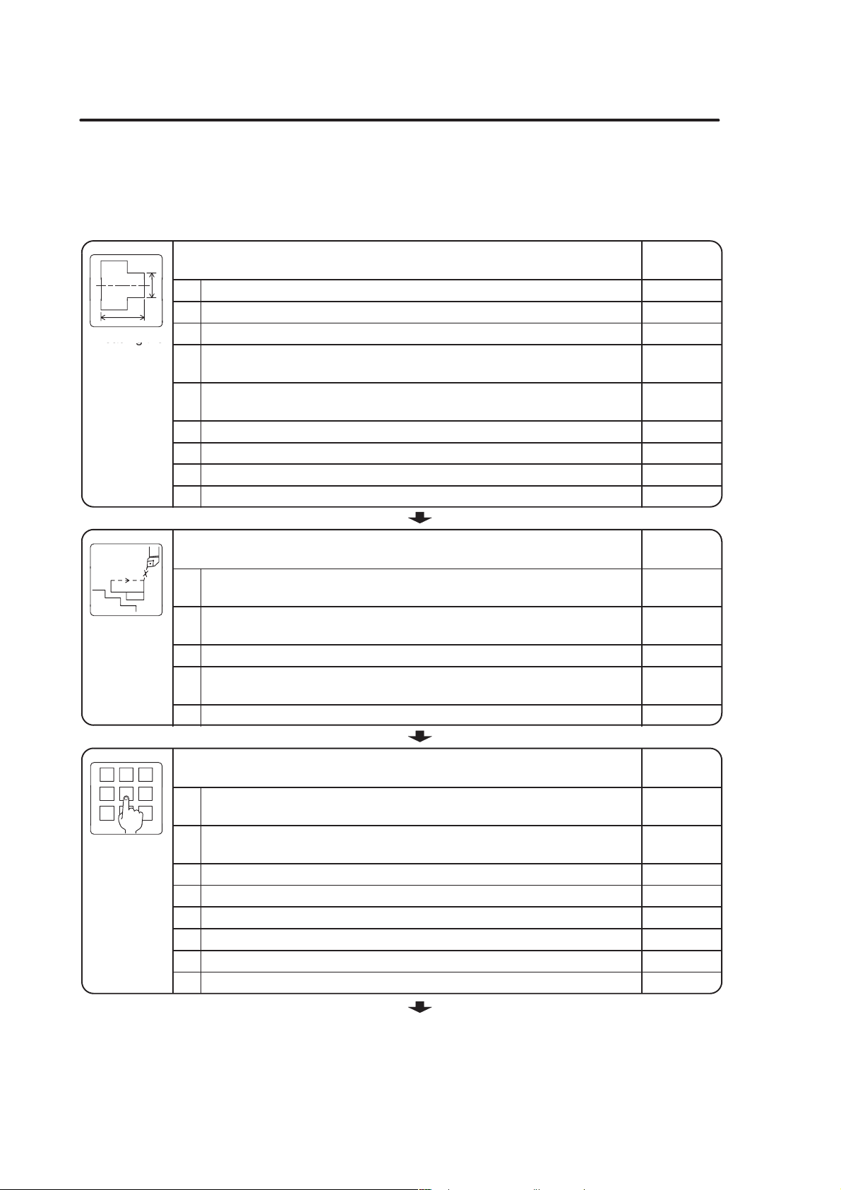
1) Examine the drawing to determine the machining required
BEFORE PROGRAMMING A–3
Production
planning and
programming
Setup operation
Mass
production
2) Determine the tools to be used
“TOOLING SYSTEM”
in the MAINTENANCE INFORMATION
3) Examine the chucking method and the fixtures
4) Create the program
5) Turn on the power supply
6) Store the program into memory
7) Check or adjust the chucking pressure
8) Shape soft jaws
“SHAPING SOFT JAWS FOR FINISHING” in the OPERATION
MANUAL
9) Mount the tools and workpiece to the machine
10) For the center-work, set the tailstock
Check or adjust the tailstock spindle thrust
(Tailstock specification)
“TURNING ON THE POWER” in the MAINTENANCE
INFORMATION
“TURNING ON THE POWER” in the OPERATION
MANUAL
“PROGRAM EDITING” in the OPERATION
MANUAL
Instruction manual supplied by the NC unit
manufacturer
“Adjusting the pressure” and
“ADJUSTING THE CHUCKING
PRESSURE” in the OPERATION
MANUAL
Instruction manual supplied by the NC
unit manufacturer
“MANUAL OPERATION” in the
OPERATION MANUAL
“TOOLING SYSTEM” in the
MAINTENANCE INFORMATION
“TAILSTOCK OPERATION”
“CAUTIONS ON CHUCKING A
WORKPIECE”
“ADJUSTING THE TAILSTOCK
SPINDLE THRUST” in the
OPERATION MANUAL
11) Measure and input the tool geometry offset value
12) Set the workpiece zero point
“SETTING OF COORDINATE SYSTEM” in the
OPERATION MANUAL
13) Check the program by carrying out dry run operation
(Correct the program if necessary)
14) Check the machining condition by carrying out test cutting
(Correct the program if necessary)
(Input the tool wear offset value if necessary)
15) Machine the workpiece in automatic operation
16) Product is completed
“SETTING OF
COORDINATE SYSTEM” in
the OPERATION MANUAL
“PREPARATION
BEFORE STARTING
MASS PRODUCTION”
in the OPERATION
MANUAL
“PREPARATION
BEFORE
STARTING MASS
PRODUCTION” in
the OPERATION
MANUAL
Page 38
A–4 BEFORE PROGRAMMING
Reading the
Conditi
of Machining
Program
5.2 Check Items
The items to be checked in the course of programming and before starting machine
operation are summarized in the following tables. Check these items to ensure smooth
operation.
Reading the
Drawing
Order and
ons
Check Items
1. Are tolerances readable on the drawing?
2. Are the symbols used to indicate accuracy understandable?
Are the shape and material of the workpiece blank made clear?
3.
Are the processes before and after the processes to be carried out on the
4.
NC lathe made clear?
Can the workpiece be machined to the specified accuracies on the NC
5.
lathe?
6. Are the keys for machining understandable?
7. Is the use of the workpiece made clear?
8. Have you read all the dimensions and notes on the drawing?
9. Is the drawing kept clean, with no unnecessary information entered on it?
Check Items
Are the order of machining and machining conditions determined in
1.
accordance with the shape and material of the workpiece blank?
Are the chucking method and chucking pressure setting determined
2.
correctly?
3. Are the cutting tools and replaceable tips selected correctly?
Are the machining processes appropriate for the shape and material of the
4.
workpiece blank?
5. Is machining free of interference?
Check
Column
Check
Column
123
64975
Inputting the
Check Items
When inputting the program for a particular process, is the program for the
1.
next process taken into consideration?
Is the program being written to suit the shape and material of the workpiece
2.
blank?
3. Is a decimal point entered in all numerical values?
4. Is the sign (+, –) preceding numerical values correct?
5. Are feed modes (rapid traverse and cutting feed) used correctly?
6. Are approach paths and cutting feed identified?
7. Is all input data checked for correctness?
8. Is the program free of errors caused by lack of concentration?
(To the next page)
Check
Column
Page 39

BEFORE PROGRAMMING A–5
g
g
Shaping and
Mounting the
Mountin
the Tools
Soft Jaws
Check Items
1. Are tool holders and cutting tools cleaned before mounting?
2. Are the replaceable tool tips new?
3. Are the material and shape of replaceable tool tips appropriate?
4. Are replaceable tool tips mounted securely and correctly?
5. Is the tool overhang appropriate?
6. Is the replaceable tool tip mounting angle correct?
7. Are mounting bolts tightened securely and evenly?
8. Is the tool nose center height correct?
Check Items
1. Are the soft jaws and master jaws cleaned before mounting?
2. Are the soft jaw mounting positions correct?
3. Are the soft jaw mounting bolts tightened securely and evenly?
4. Is the mounting bolt length appropriate?
5.
Is the plug (ring) used for shaping the soft jaws to the correct size?
6. Is the chucking pressure checked and adjusted?
7. Is the DOOR INTERLOCK key-switch placed in the NORMAL position?
8. Is the front door closed?
Are the cutting tools, replaceable tool tip, spindle speed, and feedrate all
9.
correct for shaping soft jaws?
10. Is the workpiece contact face area appropriate?
11. Is relief provided at the soft jaw corners?
12. Are run-out on I.D. and end face waviness measured?
Check
Column
Check
Column
Tool Offset
Check Items
Is due consideration given to possible interference during measurement of
1.
tool offset data?
Are the spindle speed, feedrate, and depth of cut used for the measuring
2.
tool offset data appropriate?
3. Is the DOOR INTERLOCK key-switch placed in the NORMAL position?
4. Is the front door closed?
5. Is the standard tool selection appropriate?
6. Is the measured dimension correct?
7. Is the calculation for offset data correct?
8. Is the offset direction correct?
9. Is the tool offset number correct?
Are the tool geometry offset data, tool wear offset data, and coordinate
10.
system used for offset identified correctly?
(To the next page)
Check
Column
Page 40

A–6 BEFORE PROGRAMMING
Dry Run
Operation
Test Cutting
Operation
TEST
Check Items
1. Is the chucking pressure been checked and adjusted?
If performing center work, is the tailstock spindle thrust checked and
2.
adjusted?
Is the DOOR INTERLOCK key-switch placed in the NORMAL position?
3.
4. Is the front door closed?
5. Is the single block function turned on?
6. Are the feedrate and spindle speed appropriate for operation?
7. Are the feed modes (rapid traverse and cutting feed) used correctly?
8. Is the tool retraction direction after cutting correct?
9. Is tool movement smooth in the calculated area?
10. Are the tools free of interference with the workpiece, soft jaws, and chuck?
Is the turret head indexed at a position where there is no interference with
11.
the workpiece?
12. Can the machine be stopped immediately when necessary?
Check Items
1. Is the chucking pressure been checked and adjusted?
If performing center work, is the tailstock spindle thrust checked and
2.
adjusted?
3. Is the DOOR INTERLOCK key-switch placed in the NORMAL position?
4. Is the front door closed?
5. Is the single block function turned on?
6. Are the feedrate and spindle speed appropriate for operation?
Are the order of machining and machining conditions determined in
7.
accordance with the shape and material of the workpiece blank?
8. Are cutting tools and replaceable tool tips selected properly?
9. Is the workpiece chucking method correct?
10. Is the progress of cutting been observed?
11. Are coolant supply volume and direction correct?
Are the cutting tools free of interference with the workpiece, soft jaws and
12.
chuck?
13. Are the dimensions measured after the rough cutting process?
14. Are the settings for feed override and rapid traverse override correct?
15. Can the machine be stopped immediately when necessary?
Check
Column
Check
Column
(To the next page)
Page 41

BEFORE PROGRAMMING A–7
Measuring
Production
Mass
Check Items
1. Is the measuring instrument functioning correctly?
2. Is the choice of measuring instrument correct?
3. Is the measuring order correct?
4. Is the measuring method appropriate?
5. Is the area to be measured indicated clearly?
6. Is the area to be measured free of chips and coolant?
7. Are the dimensions measured after the rough cutting process?
8. Is the workpiece cool when the dimensions are measured?
Check Items
1. Is the DOOR INTERLOCK key-switch placed in the NORMAL position?
2. Is the front door closed?
Are all NC functions such as single block functions used to check the
3.
program turned off?
4. Is dimensional variation checked?
5. Are run-out on I.D. and O.D., and end face waviness measured?
Is a target work time established on the basis of the machining time for one
6.
workpiece?
7. Is tool nose wear observed?
8. Are the dimensions measured after the rough cutting process?
Check
Column
Check
Column
Page 42

A–8 BEFORE PROGRAMMING
6. Terms for Programming
This section describes the basic terms that must be understood for creating a program.
6.1 Program Number
Several programs can be stored in the NC memory.
Program numbers are used to keep multiple programs arranged in numerical order.
Program numbers appear at the beginning of a program stored in the memory.
A program number is set by inputting numbers four digits or less after the alphabet “O”.
Numbers from 1 to 9999 can be used.
O0001; Program number
N1;
G50 S2000;
G00 T0101;
... ...
G00 X150.0 Z100.0;
M01;
N2;
G50 S2000;
G00 T0202;
M30;
If a program number to be input is already in the memory, that number, and
therefore that program cannot be input. Change its number to input the program.
The program number can have less than four significant digits. It can be input
using less than four digits.
For example, even if a program number is input as O1, the screen will automatically
display “O0001”.
Page 43

6.2 Sequence Number
The sequence number is used to search for or call the position that is being executed, or
to facilitate finding the position you want to edit in the program easily.
The sequence number is expressed as a number of five digits or less (1 to 99999),
following the letter “N”.
Generally, the sequence numbers are assigned to the part programs for individual cutting
tools in the ascending order in the order the machining processes are executed.
O0001;
N1; Sequence number
G50 S2000;
G00 T0101;
... ...
BEFORE PROGRAMMING A–9
G00 X150.0 Z100.0;
M01;
N2; Sequence number
G50 S2000;
G00 T0202;
M30;
1 If a sequence number consists of more than five digits, the five digits from the
least significant position are recognized as the sequence number.
2 The sequence number is not necessarily specified. Also, it is not necessary to
input numbers with five significant digits.
If a program is too long and exceeds the memory capacity, put the sequence
numbers at the beginning of the program for each process, or do not specify
these numbers. This will help save memory capacity.
6.3 Part Program
The part program refers to the program which contains all the information necessary for
executing the cutting process to be carried out by a single cutting tool.
Each process (1st process, 2nd process...) for machining a component contains the part
programs for as many tools as are necessary to complete each process.
Page 44

A–10 BEFORE PROGRAMMING
O0001;
N1;
G50 S2000;
G00 T0101;
... ...
G00 X150.0 Z100.0;
M01;
N2;
G50 S2000;
G00 T0202;
M30;
Part program for the tool No. 1
Part program for the tool No. 2
6.4 Address
An address is expressed using letters of the alphabet.
6.5 Data
The numbers (including the sign and decimal point) that follow the address are called the
“data”.
In addition, the information (program and other) to be input to the NC for machining
the workpiece is also called the data. Determine the type of data from the
explanation of the statement.
G00 X150.0 Z100.0;
Address
G00 X150.0 Z100.0;
Data
Page 45

6.6 Word
A word is the minimum unit for specifying functions. A word consists of an address and
the data.
6.7 Block
A block is the minimum command unit necessary to operate a machine (including the NC
unit). It is also the minimum unit used to create a part program. A block consists of
words.
On the program sheet, each one line corresponds to one block.
O0001; First block. . . . . . . . . . . . . . . . . . . . . . . . . . . . . . . . . . . . . . . . . . . . . . . . . . . . . .
N1; Second block. . . . . . . . . . . . . . . . . . . . . . . . . . . . . . . . . . . . . . . . . . . . . . . . . . . . . . . . . .
BEFORE PROGRAMMING A–11
G00 X150.0 Z100.0;
Word
G50 S2000; Third block. . . . . . . . . . . . . . . . . . . . . . . . . . . . . . . . . . . . . . . . . . . . . . . . . .
Specify the end of a block with [ ; ].
6.8 Summary
A program consists of words, a combination of address and data, and of blocks, a
combination of words, as shown below.
O0001;
N1;
G50 S2000;
G00 T0101;
Word
...
DataAddress
+
Program number
Sequence number
1 block
Part
program
Program
G00 X150.0 Z100.0;
M01;
N2;
G50 S2000;
G00 T0202;
M30;
...
Sequence number
Part
program
1 block
Page 46
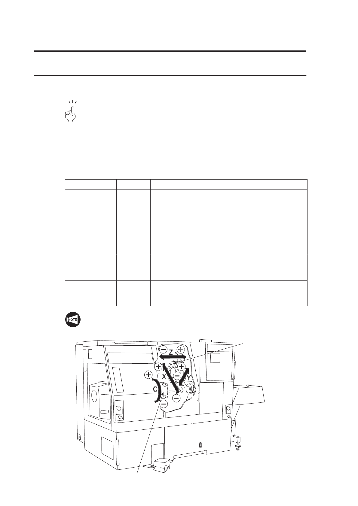
A–12 BEFORE PROGRAMMING
7. Axis Control and Direction
This section describes movement along the controlled axes and its relationship with the
program.
Knowing the direction of the controlled axes is essential when creating a program.
7.1 Movement along the Controlled Axes
This section deals with the axis definition and how the axis movement is defined in
programming.
7.1.1 SL, TL Series
In the SL, TL series, the controlled axes and their directions are determined as follows:
Axis
Unit + and – Direction
+ direction: The direction in which the machining
X Turret
diameter increases.
(the direction in which a cutting tool moves
away from the spindle center line.)
+ direction: The direction in which a cutting tool moves
Z Turret
away from the spindle.
(the direction in which the cutting tool is
viewed from the spindle.)
C
(MC type, Y-axis
specification)
Y
(Y-axis
specification)
Spindle
Turret
– direction: The rotation direction in which the
right-hand thread advances when viewing a
cutting tool from the spindle.
+ direction: The direction in which a cutting tool moves
up when viewing the machine from the
front.
For the X-axis reversed JIS specification machine, positive and negative directions
of the X-axis are reversed from those applied to conventional specification
machines.
Turret
Headstock
(chuck)
Tailstock
Page 47
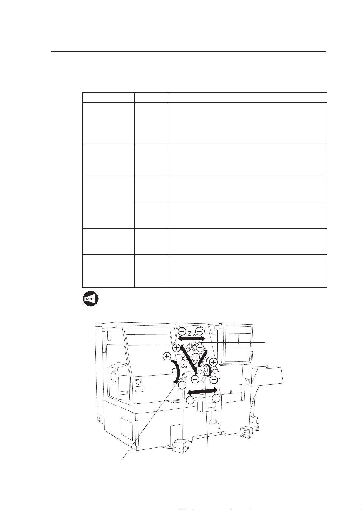
7.1.2 SL-S Series
(MC type, Y-axis
In the SL-S series, the controlled axes and their directions are determined as follows:
BEFORE PROGRAMMING A–13
Axis
X Turret
Z Turret
C
specification)
Y
(Y-axis
specification)
B Spindle 2
Unit + and – Direction
+ direction: The direction in which the machining
diameter increases.
(the direction in which a cutting tool moves
away from the spindle (spindle 1 or spindle
2) center line.)
+ direction: The direction in which a cutting tool moves
away from spindle 1.
(the direction in which the cutting tool is
viewed from spindle 1.)
– direction: The rotation direction in which the
Spindle 1
right-hand thread advances when viewing a
cutting tool from spindle 1.
+ direction: The rotation direction in which the
Spindle 2
right-hand thread advances when viewing a
cutting tool from spindle 2.
+ direction: The direction in which a cutting tool moves
Turret
up when viewing the machine from the
front.
+ direction: The direction in which spindle 2 moves
away from spindle 1.
(the direction in which spindle 2 is viewed
from spindle 1.)
For the X-axis reversed JIS specification machine, positive and negative directions
of the X-axis are reversed from those applied to conventional specification
machines.
Turret
B
Spindle 2
Spindle 1
Page 48

A–14 BEFORE PROGRAMMING
7.1.3 VL Series
In the VL series, the controlled axes and their directions are determined as follows:
Axis
Unit + and – Direction
+ direction: The direction in which the machining
X Turret
diameter increases.
(the direction in which a cutting tool moves
away from the spindle center line.)
+ direction: The direction in which a cutting tool moves
Z Turret
away from the spindle.
(the direction in which the cutting tool is
viewed from the spindle.)
For the X-axis reversed JIS specification machine, positive and negative directions
of the X-axis are reversed from those applied to conventional specification
machines.
+Z
–X
+X
Turret
–Z
Chuck
Page 49

7.1.4 LL Series
Z
In the LL series, the controlled axes and their directions are determined as follows:
BEFORE PROGRAMMING A–15
Axis
X
Unit + and – Direction
+ direction: The direction in which the machining
diameter increases.
Front-side turret
Rear-side turret
Front-side turret
Rear-side turret
+ direction: The direction in which the machining
+ direction: The direction in which a cutting tool
(the direction in which a cutting tool
moves away from the center of
rotation)
diameter decreases.
(the direction in which a cutting tool
moves toward the center of rotation)
moves away from the workpiece.
(the direction in which the cutting tool
is viewed from the spindle.)
Page 50

A–16 BEFORE PROGRAMMING
7.1.5 CL Series
In the CL series, the controlled axes and their directions are determined as follows:
Axis Unit + and – Direction
X Turret
Z Turret
For the X-axis reversed JIS specification machine, positive and negative directions
of the X-axis are reversed from those applied to conventional specification
machines.
Turret
+ direction: The direction in which the machining
diameter increases.
(the direction in which a cutting tool moves
away from the spindle center line.)
+ direction: The direction in which a cutting tool moves
away from the spindle.
(the direction in which the cutting tool is
viewed from the spindle.)
Spindle
Page 51

7.2 Expressing Axis Movement in Programming
When writing a program, the numerical values used for specifying axis position and
positive/negative sign used for determining axis movement direction vary depending on the
position taken as the reference for programming.
The reference position (workpiece zero point) and axis movement direction are determined
as follows:
BEFORE PROGRAMMING A–17
<SL, TL series>
Headstock
–Z
direction
Workpiece zero point
To write a program, the origin for the program, e.g. the
workpiece zero point must be determined.
The workpiece zero point (X0, Z0) is taken as the reference for
programming and also for machining.
X-axis The diametral dimensions of a product are expressed using
address X. X0 is taken on the center line of the product.
Z-axis The longitudinal dimensions of a product are expressed using
address Z. Z0 is taken on the end face of the finished product.
C-axis
(MC type, Y-axis
Spindle index angle for executing milling is expressed using
address C. C0 is taken at the zero point of the C-axis.
specification)
Y-axis
(Y-axis specification)
The dimensions measured in right angle direction to X-axis and
Z-axis are expressed using address Y. Y0 is taken on the
spindle center line.
<Chuck work> <Center work>
Turret
Headstock
+Z direction
–Z
direction
+X
–Z
–X
–Z
+X direction
area
area
–X direction
+X
area
+Z
Workpiece
Workpiece zero
point (X0, Z0)
–X
area
+Z
+X
–Z
Workpiece
–X
–Z
+X direction
+X
area
+Z
–X
area
+Z
–X direction
Turret
Tailstock
area
+Z direction
Workpiece zero
point (X0, Z0)
area
<X-axis and Y-axis>
Used in Y-axis specification machine.
–X
area
+Y
–X direction
–X
area
–Y
+Y direction
–Y direction
+X
area
+Y
Workpiece zero point (X0, Y0)
+X
area
–Y
+X direction
Page 52

A–18 BEFORE PROGRAMMING
<SL-S series>
<Headstock 1 side> <Headstock 2 side>
+X direction
+X
+Z
Workpiece
Workpiece zero
point (X0, Z0)
–X
+Z
Headstock 1
–Z
direction
+X
–Z
–X
–Z
area
area
–X direction
In cutting off operation, spindle 2 moves in the Z-axis direction when it receives a
workpiece from spindle 1.
With the SL-S series, this movement is made along the B-axis.
area
+Z direction
area
Turret
Turret
–Z direction
Workpiece zero
point (X0, B0)
+X direction
+X
area
–Z
Workpiece
–X
area
–Z
–X direction
+X
+Z
–X
+Z
area
Headstock 2
+Z direction
area
<VL series>
<Chuck work>
–X direction
–X
+Z
–X
–Z
area
area
+Z direction
–Z direction
Turret
+X
area
+Z
Workpiede zero point (X0, Z0)
+X direction
Workpiece
+X
area
–Z
Headstock
Page 53
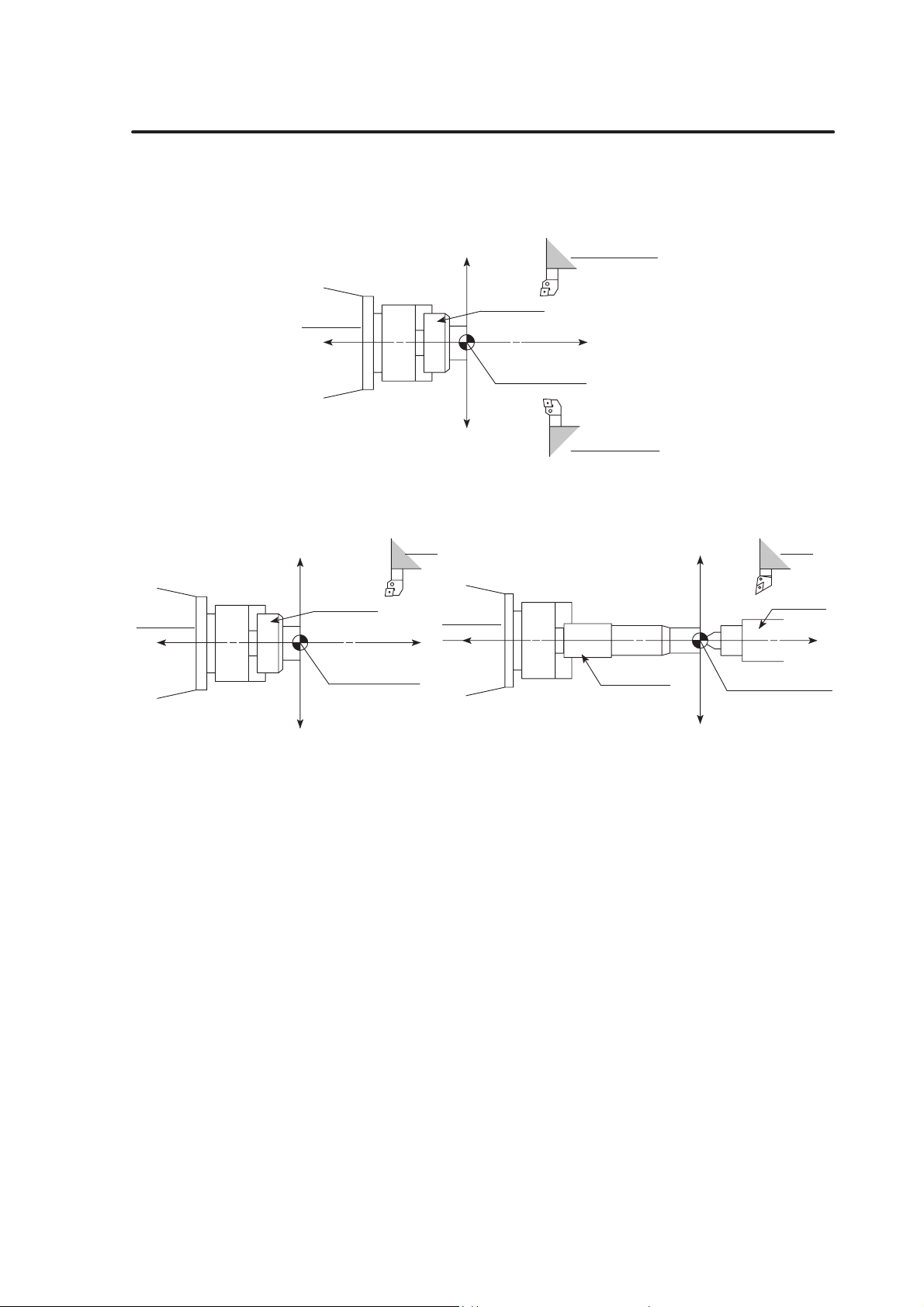
<LL series>
<Chuck work>
Headstock
–Z direction
–X
–Z
–X direction
area
–X
area
+Z
Workpiece
+Z direction
Workpiece zero
point (X0, Z0)
BEFORE PROGRAMMING A–19
Rear-side turret
<CL series>
Headstock
–Z
direction
+X
–Z
area
+X direction
+X
+Z
area
Front-side turret
<Chuck work> <Center work>
Turret
Headstock
+Z direction
–Z
direction
+X
–Z
–X
–Z
+X direction
area
area
–X direction
+X
area
+Z
Workpiece
Workpiece zero
point (X0, Z0)
–X
area
+Z
+X
–Z
Workpiece
–X
–Z
+X direction
+X
area
+Z
–X
area
+Z
–X direction
Turret
Tailstock
area
+Z direction
Workpiece zero
point (X0, Z0)
area
Page 54

A–20 BEFORE PROGRAMMING
8. Specifying the Dimensions
To specify tool movement from the presently located point to the next point (target point),
the following two types of commands can be used.
1) Absolute commands
2) Incremental commands
When writing a program, it is necessary to understand the nature of these two types of
dimension specifying commands.
This section deals with the basic and the command specifying method for using the
absolute and incremental commands in a program.
8.1 Absolute Commands
Absolute commands define a specific point by the distance from the workpiece zero point
(X0, Z0) with a (+) or – sign.
1 In a program using absolute commands, the axes are expressed using the
following address characters:
–Z direction
X-axis³X_ ; Z-axis³Z_ ;
2 With the SL-S series, absolute commands of the B-axis is expressed as “B_ ;”.
3 With the Y-axis specification machine, absolute commands of the Y-axis is
expressed as “Y_ ;”.
4 With the MC type and the Y-axis specification machine, absolute commands of
the C-axis is expressed as “C_ ;”.
Specifying the absolute commands (1)
To express tool movement from point
+X direction
10
+X
–Z
–X
–Z
area
area
2
(10.0, –5.0)
–5 10
5
Workpiece zero point (X0, Z0)
–X direction
1
(20.0, 10.0)
+X
area
+Z
–X
area
+Z
to point 2 using absolute commands.
1
X20.0 Z10.0;
. . . . . . . . . . . . . . . .
X10.0 Z–5.0;
+Z direction
1
. . . . . . . . . . . . . . . .
2
For the X-axis, since dimensions are all expressed in diametral values, actual
X-axis movement distance is a half of the specified value.
Page 55

BEFORE PROGRAMMING A–21
1 The positive (+) sign may be omitted.
X+10.0³X10.0 Z+10.0³Z10.0
2 The values specified as (f, f) in the illustration above indicate the coordinate
values (X, Z).
Specifying the absolute commands (2)
To express tool movement (point
absolute commands.
50
5
4
2
3
C10
1
(X0, Z0)
X40.0
C5
C5
1
∅ 50
∅ 100
2
1
∅ 50
∅ 40 55
³ point 2 ³ point 3 ³ point 4 ³ point 5) using
1
X40.0 Z0;
X50.0 Z–5.0;
(X50.0) Z–50.0;
X80.0 (Z–50.0);
X100.0 Z–60.0;
. . . . . . . . . . . . . . . . . . .
. . . . . . . . . . . . . . . .
. . . . . . . . . . . . . .
. . . . . . . . . . . . . .
. . . . . . . . . . . . . .
1
2
3
4
5
Since the commands in ( ) are the same as
in the previous block, they can be omitted.
To determine X coordinate of point
, subtract C5
1
chamfer size (5 mm) from the workpiece diameter
50 mm.
Chamfer size 5 mm should be converted
into diametral value.
5 mm 2 = 10 mm
∅50 – (5 2) = 40
∅ 100
X80.0 and 5 Z–60.0
4
C10
5
10
4
10
50
∅ 50
Therefore, X coordinate of point 1 is X40.0.
To determine X coordinate of point
, subtract
4
C10 chamfer size (10 mm) from the workpiece
diameter 100 mm.
Chamfer size 10 mm should be converted
into diametral value.
10 mm 2 = 20 mm
∅100 – (10 2) = 80
Therefore, X coordinate of point
To determine Z coordinate of point
is X80.0.
4
, add
5
chamfer size 10 mm to 50 mm. Since the Z
dimensions are all measured in the negative
direction from the workpiece zero point, the
calculation should be,
(–50) + (–10) = –60
Therefore, Z coordinate of point
is Z–60.0.
5
Page 56

A–22 BEFORE PROGRAMMING
8.2 Incremental Commands
Incremental commands define relative position on a given coordinate system by specifying
the motion distance from the present position. The positive sign indicates that the position
to be defined is in the positive direction from the present position.
For the B-axis, an incremental command cannot be used.
1 In a program using incremental commands, the axes are expressed using the
following address characters:
X-axis³U_ ; Z-axis³W_ ;
2 With the Y-axis specification machine, incremental commands of the Y-axis is
expressed as “V_ ;”.
3 With the MC type and the Y-axis specification machine, incremental commands
of the C-axis is expressed as “H_ ;”.
Specifying the incremental commands (1)
–Z direction
To express tool movement from point
+X direction
10
+X
–Z
–X
–Z
area
area
2
(10.0, –5.0)
–5 10
5
Workpiece zero point (X0, Z0)
–X direction
For the X-axis (U command), since dimensions are all expressed in diametral
values, actual X-axis movement distance is a half the specified value.
1 The positive (+) sign may be omitted.
U+10.0³U10.0 W+15.0³W15.0
2 The values specified as (f, f) in the illustration above indicate the coordinate
values (X, Z).
1
(20.0, 10.0)
+X
area
+Z
–X
area
+Z
to point 2 using incremental commands.
1
X20.0 Z10.0;
. . . . . . . . . . . . . . . .
U–10.0 W–15.0 ;
+Z direction
1
. . . . . . . . . . . . .
2
Page 57

Specifying the incremental commands (2)
BEFORE PROGRAMMING A–23
To express tool movement (point
incremental commands.
50
5
4
2
3
C10
(X0, Z0)
U10.0 W–5.0
2
C5
C5
1
∅ 50
∅ 100
2
1
∅ 50
∅ 40 55
³ point 2 ³ point 3 ³ point 4 ³ point 5) using
1
X40.0 Z0;
U10.0 W–5.0;
(U0) W–45.0;
U30.0 (W0);
U20.0 W–10.0;
. . . . . . . . . . . . . . . . . . .
. . . . . . . . . . . . . . .
. . . . . . . . . . . . . . . .
. . . . . . . . . . . . . . . . .
. . . . . . . . . . . . . .
1
2
3
4
5
Since the commands in ( ) are the same as
in the previous block, they can be omitted.
X coordinate value of point
of C5 (5 mm) is executed from point
point
.
2
is X50.0; chamfering
2
(X40.0) to
1
Chamfer size 5 mm should be converted
into diametral value.
5 mm 2 = 10 mm
Therefore, coordinate value of U is U10.0.
∅ 100
U30.0 (W0) and 5 U20.0 W–10.0
4
C10
10
5
4
3
10
50
∅ 50
Z coordinate value of point
is Z–5.0; Z-axis
2
moves 5 mm in the negative direction from point
(Z0).
1
Therefore, coordinate value of W is W–5.0.
X coordinate value of point
is X80.0; X-axis
4
moves 30 mm in the positive direction from point
(X50.0).
3
Therefore, coordinate value of U is U30.0.
Tool movement from point
to point 4 is
3
made only in the X-axis direction. In such a
case, Z-axis movement command (W0) may
be omitted.
X coordinate value of point
is X100.0;
5
chamfering of C10 (10 mm) is executed from point
(X80.0) to point 5.
4
Chamfer size 10 mm should be converted
into diametral value.
10 mm 2 = 20 mm
Therefore, coordinate value of U is U20.0.
Page 58

A–24 BEFORE PROGRAMMING
8.3 Summary
Differences between absolute programming and incremental programming are
summarized below.
Address Characters
Meaning of the Sign
(+/–)
Meaning of the
Numerical Values
Reference Point of
Commands
Z coordinate value of point
is Z–60.0; Z-axis
5
moves 10 mm in the negative direction from point
(Z–50.0).
4
Therefore, coordinate value of W is W–10.0.
Absolute Programming Incremental Programming
X_ Z_ Y_ C_ ; B_ ; U_ W_ V_ H_ ;
The area where the specified
point exists.
Coordinate values
(distance from the workpiece
zero point, angle of index from
the zero point)
Workpiece zero point
(X0, Z0, Y0)
Zero point (C0) (B0)
The direction in which the
cutting tool advances.
Distance of tool movement,
angle of spindle index
Actual positions of tool and
spindle
1 Generally, a program is written using absolute commands.
Incremental commands are usually used for tool retraction or chamfering
operation.
2 Absolute commands and incremental commands may be specified in the same
block such as “X_ W_ ;”, “U_ Z_ ;”, and “X_ V_ ;”.
3 If absolute and incremental commands representing the same axis (X and U, Z
and W, Y and V, or C and H) are specified in the same block, the address
character specified later becomes valid.
Example: X10.0 U–20.0; ³ U–20.0 is valid.
Page 59

9. Specifying the Cutting Conditions
BEFORE PROGRAMMING A–25
Cutting feedrate
Depth
of cut
Spindle speed
1) Spindle speed (min
The spindle speed or cutting speed is specified directly following address S
(S function).
COMMAND
G97 S400; Spindle speed 400 min
–1
), cutting speed (surface speed) (m/min)
. . . . . . . . . . . .
The cutting conditions that are set when
programming have a great influence on the
machining efficiency and accuracy. These
conditions must be checked carefully.
The following four cutting conditions are necessary
for machining the workpiece.
–1
G96 S200; Cutting speed 200 m/min. . . . . . . . . . . .
2) Cutting feedrate (mm/rev) (mm/min)
Feedrate is specified directly following address F (F function).
COMMAND
G99 F0.1; Feedrate per spindle revolution, 0.1 mm/rev. . . . . . . . . . . . .
G98 F100; Feedrate per minute, 100 mm/min. . . . . . . . . . . .
3) Depth of cut
There is no special function used to specify the depth of cut. Depth of cut is specified
using tool movement along the X- or Z-axis.
For multiple repetitive cycles, depth of cut may be specified using an address.
For details of multiple repetitive cycles, refer to Chapter H “MULTIPLE
REPETITIVE CYCLES”.
Page 60

A–26 BEFORE PROGRAMMING
4) Chuck gripping force
The chuck gripping force is reduced when the spindle is rotated
since the rotation applies centrifugal force to the chuck jaws. This
reduction of the chuck gripping force could cause the workpiece to
fly out of the chuck during machining, causing serious injuries or
damage to the machine. Therefore, when checking a program,
measure the chuck gripping force that will actually be applied when
the spindle is rotated at the speed used for machining by using a
gripping force meter. If the measured chuck gripping force value is
lower than that required to hold the workpiece safely, change
machining conditions such as the chucking pressure, spindle
speed, feedrate, and depth of cut.
Periodically measure the chuck gripping force with a gripping force
meter to make sure that the required gripping force is maintained. If
it is not, consult the chuck manufacturer and cylinder manufacturer.
For details on the relationship between the spindle rotation speed
and chuck gripping force, refer to the instruction manuals prepared
by the chuck manufacturer and cylinder manufacturer.
For details of chuck gripping force, refer to the instruction manuals prepared by
the chuck and cylinder manufacturers.
Page 61

10. Basic Pattern of Program
10.1 Chuck-Work Programming
When creating a part program for each tool (O.D. cutting tool, thread cutting tool etc.), the
following basic patterns are used.
O0001; Program number (This is specified only once at the beginning of all programs.)
N1; Sequence number (This is specified at the beginning of a part program.)
G50 S_ ; Specifies the maximum spindle speed for clamping. In the G96
(constant surface speed control) mode, spindle speed is clamped at
this speed if a command requiring a higher speed is specified.
G00 T0101 M41(M42, M43, M44);
Specifies the tool number, the tool offset number, and the spindle
speed range.
G96 S150 M03(M04); G96 specifies the cutting speed (150 m/min).
or,
G97 S150 M03(M04); G97 specifies the spindle or spindle 1 speed (150 min
direction of rotation.
M03: Normal
M04: Reverse
(G00) X_ Z20.0 M08; Approach to the workpiece at a rapid traverse
*
G01 X_ Z_ F_ ; Approach to the workpiece at a cutting feedrate to ensure safety.
...... ...
Start of coolant supply
BEFORE PROGRAMMING A–27
–1
) and the
When specifying rapid approach to the workpiece, study
the workpiece shape carefully. For the approach in the
Z-axis direction, positioning must be made at a point
“chucking amount + 10 mm” away from the end face of
the workpiece.
Machining program
G00 U1.0 Z20.0 M09; Escape from the machining area, stop of coolant supply
For I.D. cutting, determine the escape stroke depending
on the diameter having been machined. Note that the
escape U command must be specified as U–_.
X_ Z_ ; Move to a position where the turret head can be rotated.
M01; Optional stop
The part program same as *
Part programs are written for each tool.
M01; Optional stop
The part program same as *
The spindle stop command (M05) is entered in the last part program.
Part programs are written for each tool.
M30; End of program
M41 to M44 commands can be specified only for the machine equipped with a
transmission.
Page 62

A–28 BEFORE PROGRAMMING
10.2 Center-Work Programming
O0001; Program number (This is specified only once at the beginning of all programs.)
N1; Sequence number (This is specified at the beginning of a part program.)
G50 S_ ; Specifies the maximum spindle speed for clamping. In the G96
(constant surface speed control) mode, spindle speed is clamped at
this speed if a command requiring a higher speed is specified.
G00 T0101 M41(M42, M43, M44);
Specifies the tool number, the tool offset number, and spindle speed
range.
G96 S150 M03(M04); G96 specifies the cutting speed (150 m/min).
or,
G97 S150 M03(M04); G97 specifies the spindle speed (150 min
rotation.
M03: Normal
*
M04: Reverse
Z_ M08; Approach to the workpiece (Z-axis direction)
Start of coolant supply
X_ ; Approach to the workpiece (X-axis direction)
... ......... ......
Machining program
–1
) and the direction of
If the cutting tool might interfere with the center, stop the
rapid traverse at a safe point and continue the approach
at a cutting feedrate (G01). The feedrate for approach
should be a little faster than a cutting feedrate.
G00 X_ M09; Escape along the +X-axis, stop of coolant supply
Z_ ; Move to a position where the turret head can be rotated.
M01; Optional stop
The part program same as *
Part programs are written for each tool.
M01; Optional stop
The part program same as *
The spindle stop command (M05) is entered in the last part program.
Part programs are written for each tool.
M30; End of program
M41 to M44 commands can be specified only for the machine equipped with a
transmission.
Page 63
10.3 Both-Center-Work Programming
O0001; Program number (This is specified only once at the beginning of all programs.)
N1; Sequence number (This is specified at the beginning of a part program.)
G50 S_ ; Specifies the maximum spindle speed for clamping. In the G96
(constant surface speed control) mode, spindle speed is clamped at
this speed if a command requiring a higher speed is specified.
G00 T0101 M41(M42, M43, M44);
Specifies the tool number, the tool offset number, and spindle speed
range.
G96 S150 M03(M04); G96 specifies the cutting speed (150 m/min).
or,
G97 S150 M03(M04); G97 specifies the spindle speed (150 min
rotation.
M03: Normal
*
Z_ M08; Approach to the workpiece (Z-axis direction)
X_ ; Approach to the workpiece (X-axis direction)
............ ......
Machining program
M04: Reverse
Start of coolant supply
If the cutting tool might interfere with the center, stop the
rapid traverse at a safe point and continue the approach
at a cutting feedrate (G01). The feedrate for approach
should be a little faster than a cutting feedrate.
BEFORE PROGRAMMING A–29
–1
) and the direction of
G00 X_ M09; Escape along the +X-axis, stop of coolant supply
Z_ ; Move to a position where the turret head can be rotated.
M01; Optional stop
The part program same as *
Part programs are written for each tool.
M01; Optional stop
The part program same as *
The spindle stop command (M05) is used in the last part program.
M11; Chuck unclamp command; the STATUS indicator [ CHCL ] goes
off.
Before specifying the M30 command, execute
the M11 command. If the M11 command is not
executed and the (ST) switch is pressed
by mistake, automatic operation will start and
the operator may be injured. However, if the
workpiece is supported with the center at the
spindle side held by the chuck, do not use the
M11 command. If the M11 is specified in a
program when the center at the spindle side
is held by the chuck, the center will fall or
shift, which in turn will cause the workpiece
to fall, damaging the machine.
ST
M30; End of program
M41 to M44 commands can be specified only for the machine equipped with a
transmission.
Page 64

A–30 BEFORE PROGRAMMING
11. Cautions for Creating a Program
11.1 Program Number
This manual describes all program numbers in a four digit number. However, it is not
necessary to write or enter a program number in a four digit number. A program number
specified in less than four digit number is recognized and displayed in a four digit number
after it is input to the NC. If “O1” is entered, for example, it is recognized and displayed as
“O0001”.
An entry of a program number of five or more digits is not permitted.
11.2 Space between the Words in the Program
In this manual, a program is described in the manner as indicated below.
O0001;
N1;
G50
S2000; . . . . . . . . . . . . . . . . . . .
G00
T0101;
Space
11.3 Signs and Symbols
A program is expressed in a combination of alphabetic letters, positive/negative (+/–)
signs, and numbers containing a decimal point. In addition to these, the end of block
symbol “;” and the block delete symbol “/” are used.
Block delete function:
If the block delete function is on, the commands beginning with the slash “/” are
ignored up to the end of block code “;” in the same block. The program is
continuously executed from the block not containing the slash.
In line
1
, for example, a space is placed between
“G50” and “S2000”. When entering a program to
the NC, the word-to-word space may not be
1
inserted.
When a program is input to the NC memory,
a space is automatically inserted.
If the block delete function is off, all blocks (even those preceded by a slash) are
executed.
The following signs and symbols are also used.
“,” “∗” “
[ ]” “( )” “#” “@”
Page 65

11.4 Inputting a Decimal Point
For an NC, it is possible to use a decimal point to enter numerical values. A decimal point
can be used to express the numerical values that have the unit of “distance”, “angle”,
“time”, or “speed”.
The addresses which allow the use of a decimal point are indicated below.
Distance or angle: X, Y, Z, C, U, V, W, H, I, J, K, R, B
Time: U, X
Feedrate: F
If you forget to enter a decimal point in a program entry that
requires one and start the machine without noticing the error, the
turret may move to an unexpected position, damaging the machine.
Check that you have entered decimal points where necessary.
“mm” setting (specified by G21)
X1.0 X1 mm. . . . . .
BEFORE PROGRAMMING A–31
X1
“inch” setting (specified by G20)
X0.001 mm. . . . . . .
(if a decimal point is not entered, it is assumed
that the value is specified in the unit of least input
increment.)
X1.0 X1 inch. . . . . .
X1
1 There are limits in the usable units depending on addresses. Setting units are
“mm”, “inch”, “degree” and “second”.
X0.0001 inch. . . . . . .
(if a decimal point is not entered, it is assumed
that the value is specified in the unit of least input
increment.)
X15.0 X15 mm or X15 inches
G04 U1.0 Dwell for 1 second
F10.0 10 mm/rev, 10 mm/min, 10 inch/rev, or 10 inch/min
2 In the case of a dwell command, a decimal point can be used when address X
is used. However, it is not allowed to use a decimal point if address P is used
since address P is also used to specify a sequence number.
1 To call for dwell for 1 hour, specify as
G04 U3600.0 (X3600.0);
(1 hour = 3600 seconds)
2 In a program, or in a block, it is allowed to specify the commands with and
without a decimal point.
X1000 Z23.7;
X10.0 Z22359;
Page 66

A–32 BEFORE PROGRAMMING
11.5 Role of Decimal Point
The following shows how the tool paths are generated if a decimal point is omitted
mistakenly.
Use a decimal point carefully
The program to machine the workpiece shape as illustrated below
5
∅ 100
4
C5
60
∅ 90
Rapid traverse
Cutting feed
3
2 1
C5
If “X90” is entered for “X90.0” in block
illustration below.
5
C5
C5
60
7
6
(G99) G00 X78.0 Z20.0 M08;
G01 Z1.0 F2.0;
X90.0 Z–5.0 F0.2;
Z–60.0;
X102.0 Z–66.0;
G00 U1.0 Z20.0 M09;
X200.0 Z150.0;
...
3
, the resultant tool paths are generated as in the
7
6
12
3. . . . . . . .
∅ 100
∅ 90
34
Rapid traverse
Cutting feed
Since the numerical value specified without a decimal point is regarded to have been set in
least input increment, “X90” is executed as “X0.09 mm”.
X1.0 = X1 mm
X1 = X0.001 mm
Therefore, use a decimal point when entering numerical values.
If you forget to enter a decimal point in a program entry that
requires one and start the machine without noticing the error, the
turret may move to an unexpected position, damaging the machine.
Check that you have entered decimal points where necessary.
Page 67

BEFORE PROGRAMMING A–33
12. JIS Specification and Reverse JIS Specification
This section explains items to be kept in mind when creating a program in the JIS
specification and in the reverse JIS specification.
The following summarizes the items which differ from the programming in the JIS
specification when a program is written in the reverse JIS specification.
1) For the X-axis commands, the positive/negative (+/–) sign is reversed.
Addresses for which the sign of the data is reversed: X, U, I
JIS Specification
X100.0 X–100.0
U10.0 U–10.0
I80.0 I–80.0
2) In the circular interpolation, G02 calls for rotation in the counterclockwise (CCW)
direction and G03 calls for rotation in the clockwise (CW) direction.
JIS Specification Reverse JIS Specification
G02
G03 CCW
CW CCW
Reverse JIS Specification
CW
Page 68

A–34 BEFORE PROGRAMMING
3) In the automatic tool nose R offset function (G41, G42), the offset direction is
reversed and command position of the imaginary tool nose differs.
<Offset direction>
Tool position is offset to the left side
of the tool paths in reference to the
programmed tool moving direction.
G41
Tool moving
direction
JIS Specification Reverse JIS Specification
Tool position is offset to the right
side of the tool paths in reference to
the programmed tool moving
Workpiece
direction.
Tool moving
direction
Workpiece
Tool position is offset to the right
side of the tool paths in reference to
the programmed tool moving
direction.
G42
Tool moving
direction
Workpiece
<Imaginary tool nose position>
JIS Specification Reverse JIS Specification
X+
0
R
9
3
8
162
57
4
Actual
tool
nose
Z+
Tool position is offset to the left side
of the tool paths in reference to the
programmed tool moving direction.
Workpiece
Tool moving
direction
X–
0
R
9
2
6
483
57
1
Actual
tool
nose
Z+
Page 69

BEFORE PROGRAMMING A–35
6
5
C5
∅ 100
∅ 90
∅ 60
R5
∅ 50
JIS Specification
O0001;
G50 S2000;
G00 T0101;
G96 S180 M03;
G42 X50.0 Z20.0 M08; . . . . . . . . . . . . . .
G01 Z2.0 F1.0; . . . . . . . . . . . . . . . . . . . . .
Z–30.0 F0.2; . . . . . . . . . . . . . . . . . . . . . . .
X60.0 Z–35.0; . . . . . . . . . . . . . . . . . . . . .
X90.0; . . . . . . . . . . . . . . . . . . . . . . . . . . . .
G03 X100.0 Z–40.0 R5.0; . . . . . . . . . . .
G40 G00 U1.0 Z20.0; . . . . . . . . . . . . . . .
X150.0 Z100.0 M09; . . . . . . . . . . . . . . . .
M01;
8
1
Rapid traverse
Cutting feed
30
7
34
2
Reverse JIS Specification
O0001;
G50 S2000;
G00 T0101;
G96 S180 M03;
1
G41 X–50.0 Z20.0 M08; . . . . . . . . . . . . .
2
G01 Z2.0 F1.0; . . . . . . . . . . . . . . . . . . . . .
Z–30.0 F0.2; . . . . . . . . . . . . . . . . . . . . . . .
3
X–60.0 Z–35.0; . . . . . . . . . . . . . . . . . . . .
4
X–90.0; . . . . . . . . . . . . . . . . . . . . . . . . . . .
5
G02 X–100.0 Z–40.0 R5.0; . . . . . . . . . .
6
G40 G00 U–1.0 Z20.0; . . . . . . . . . . . . . .
7
X–150.0 Z100.0 M09; . . . . . . . . . . . . . . .
8
M01;
1
2
3
4
5
6
7
8
Page 70

CHAPTER B
G FUNCTIONS
This chapter describes the G functions.
The following G functions are only outlined in this chapter and they are explained in details
in Chapters E, G, H, and I, respectively.
– Section 10. “G40, G41, G42 Automatic Tool Nose Radius Offset”: Chapter E
– Section 11. “G40, G41, G42 Cutter Radius Offset”: Chapter G
– Section 15. “G70 - G76 Multiple Repetitive Cycle”: Chapter H
– Section 16. “G80, G83 - G85, G87 - G89 Hole Machining Canned Cycles”: Chapter I
The examples of program given in this chapter all assume tool nose R0.
For the G codes not explained in this chapter, refer to the instruction manual
supplied by the NC unit manufacturer.
Page 71

CONTENTS
B : G FUNCTIONS
1. G Code List B–1. . . . . . . . . . . . . . . . . . . . . . . . . . . . . . . . . . . . . . . . . . . . . . . . . . . .
2. G00 Positioning the Cutting Tool at a Rapid Traverse Rate B–5. . . . . . . . . .
3. G01 Moving the Cutting Tool Along a Straight Path
at a Cutting Feedrate B–10. . . . . . . . . . . . . . . . . . . . . . . . . . . . . . . . . . . . . . . . . . .
4. G02, G03 Moving the Cutting Tool Along Arcs
at a Cutting Feedrate B–12. . . . . . . . . . . . . . . . . . . . . . . . . . . . . . . . . . . . . . . . . . .
5. G50 Setting the Spindle Speed Limit B–14. . . . . . . . . . . . . . . . . . . . . . . . . . . . .
6. G96 Controlling Spindle Speed
to Maintain Surface Speed Constant B–17. . . . . . . . . . . . . . . . . . . . . . . . . . . . . .
7. G97 Controlling Spindle Speed at Constant Speed B–19. . . . . . . . . . . . . . . . .
8. G04 Suspending Program Execution (Dwell) B–22. . . . . . . . . . . . . . . . . . . . . .
9. G98, G99 Setting Feedrate Units B–24. . . . . . . . . . . . . . . . . . . . . . . . . . . . . . . .
10. G40, G41, G42 Automatic Tool Nose Radius Offset B–28. . . . . . . . . . . . . . . .
11. G40, G41, G42 Cutter Radius Offset B–30. . . . . . . . . . . . . . . . . . . . . . . . . . . . .
12. G32, G92 Thread Cutting
(Continuous Thread Cutting and Thread Cutting Cycle) B–33. . . . . . . . . . . . . .
13. G32 Tapping (On the Center of Spindle) B–49. . . . . . . . . . . . . . . . . . . . . . . . . .
13.1 Cautions on Programming Tapping Using G32 B–50. . . . . . . . . . . . . .
13.1.1 Dwell Command B–50. . . . . . . . . . . . . . . . . . . . . . . . . . . . . . .
13.1.2 Precautions on Using the Tapper B–50. . . . . . . . . . . . . . . . .
13.1.3 To Finish Tapping at Correct Depth in Blind Hole B–51. . .
14. G90, G94 O.D./I.D. Cutting Cycle and Face Cutting Cycle B–53. . . . . . . . . . .
Page 72

15. G70 - G76 Multiple Repetitive Cycle B–56. . . . . . . . . . . . . . . . . . . . . . . . . . . . . .
16. G80, G83 - G85, G87 - G89 Hole Machining Canned Cycles B–58. . . . . . . .
17. G22, G23 Setting Barrier to Define the Tool Entry Inhibited Zone B–63. . . . .
18. G28 Returning the Axes to Machine Zero Automatically B–66. . . . . . . . . . . . .
19. G53 Selecting the Machine Coordinate System B–68. . . . . . . . . . . . . . . . . . . .
20. G54 - G59 Setting a Work Coordinate System B–70. . . . . . . . . . . . . . . . . . . . .
21. G38 Workpiece Pushing Check B–73. . . . . . . . . . . . . . . . . . . . . . . . . . . . . . . . . .
22. G07.1 (G107) Cylindrical Interpolation B–76. . . . . . . . . . . . . . . . . . . . . . . . . . . .
23. G12.1 (G112), G13.1 (G113)
Notching (Polar Coordinate Interpolation) B–82. . . . . . . . . . . . . . . . . . . . . . . . . .
24. G479 Tailstock Connect B–85. . . . . . . . . . . . . . . . . . . . . . . . . . . . . . . . . . . . . . . .
APPENDIX 1 Workpiece Transfer APPENDIX B–1. . . . . . . . . . . . . . . . . . . . . . . .
1.1 Work Coordinate System APPENDIX B–2. . . . . . . . . . . . . . . . . . . . . . .
APPENDIX 2 G65 P9020/G65 P9021 Workpiece Transfer
Macro Program (MSD-501II) APPENDIX B–4. . . . . . . . . . . . . . . .
APPENDIX 3 G65 P9022 Workpiece Ejection
Macro Program (MSD-501II) APPENDIX B–12. . . . . . . . . . . . . . . .
Page 73
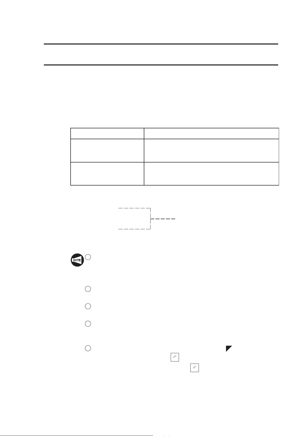
1. G Code List
G codes are also called preparatory functions. The G codes consisting of the address G
and a numerical value that follows address G define the machining method and the axis
movement mode in a specified block. The NC establishes the control mode in response to
the specified G code.
The numerical value following address G defines the commands written in that block.
Depending on how the G codes remain valid, they are classified into the following two
types:
G FUNCTIONS B–1
Type
Meaning
One-shot G code
(G codes in group 00,
The G code is valid only in the specified block.
excluding G10 and G11)
Modal G code
(G codes in groups other
than group 00)
The G code remains valid until another G code in the
same group is specified.
For example, G00 and G01 are both modal codes, that is, they are G codes in the group
other than group 00.
G01 X_ Z_ ;
X_ ;
G01 is valid in this range.
Z_ ;
G00 X_ Z_ ;
1 When specifying G codes in a block, they must be placed before the addresses
(other than G and M) which are executed under the mode they establish. If a
G code is specified after addresses for which it establishes the mode of
processing, the mode established by it is not valid to these addresses.
2 More than one G code, each belonging to a different G code group, may be
specified in the same block.
3 If more than one G code, belonging to the same group, are specified in a block,
the one specified later is valid.
4 If a G code not listed in the G code table or a G code for which the
corresponding option is not selected is specified, an alarm message (No. 010)
is displayed on the screen.
5 The NC establishes the G code modes, identified by the symbol, when the
power is turned on or when the
Concerning G54, however, pressing the
(RESET) key is pressed.
RESET
(RESET) key does not establish
RESET
the G code mode of them but the G code selected for each group remains
valid.
Page 74

B–2 G FUNCTIONS
00
21
06
09
6 *
1
: Optional for the Y-axis specification.
2
: Standard for the MC type and the Y-axis specification.
*
3
: Standard for MSD-518 and MSD-501.
*
4
: Standard for MSC-518, MSD-518, and MSD-518II.
*
5
: Standard for the SL-S series.
*
6
: Optional for the MC type and the Y-axis specification.
*
7
: Standard for the SL and the SL-S series equipped with MC type and
*
Y-axis specification (excludes the SL-400, SL-600, SL-65, and SL-75).
8
*
: Standard for the Y-axis specification of the SL-S series. Note that the 3rd
zero point is used for the retract position of the X- and Y-axes when
moving spindle 2 (B-axis) and cannot be used for other purposes.
9
*
: Not available for the MSC-500.
10
: Standard for the SL-600 series.
*
11
: Standard for the MSD-501II of SL-S series.
*
12
: Optional for the SL-25E.
*
13
*
: Not available for the VL-25, the LL series and the MSC-500.
14
: Standard for the Y-axis specification.
*
15
: Optional for MSC-500 and MSC-501.
*
f : Standard
: Option : Not available
Code Group Function Division
G00 Positioning f
G01 Linear interpolation f
G02
G03
01
Circular interpolation/helical interpolation, CW (clockwise) f/ *
Circular interpolation/helical interpolation, CCW
(counterclockwise)
f/ *
G04 Dwell f
G07.1
(G107)
G10
Cylindrical interpolation
00
Data setting
G11 Data setting mode cancel
G12.1
(G112)
G13.1
(G113)
Polar coordinate interpolation mode *
Polar coordinate interpolation mode cancel *
*
*
*
G17 XpYp plane Xp: X-axis or its parallel axis f
G18 16 ZpXp plane
G19 YpZp plane
G20
G21
G22
G23
Data input in inch system f
Data input in metric system f
Stored stroke check function ON
Stored stroke check function OFF
Yp: Y-axis or its parallel axis
Zp: Z-axis or its parallel axis
f
f
*
*
1
1
2
3
3
2
2
3
3
Page 75

G FUNCTIONS B–3
08
4
01
20
00
14
11
11
12
11
f : Standard
: Option : Not available
Code Group Function Division
G25
G26
Spindle speed variation detection OFF
Spindle speed variation detection ON *
*
G27 Reference point return check f
G28 Reference point return f
G30
G30.1 Floating reference point return
G31 Skip function/Multi-step skip function
Second/third, fourth reference point return
00
f/
*
f/
G32 Thread cutting f
G34
G35
G36 Circular thread cutting, CCW (counterclockwise)
Variable lead thread cutting
Circular thread cutting, CW (clockwise)
*
*
G38 00 Workpiece pushing check *
G40 Tool nose radius offset cancel/Cutter radius offset cancel f/ *
G41 07 Tool nose radius offset, left/Cutter radius offset, left f/ *
G42 Tool nose radius offset, right/Cutter radius offset, right f/ *
G50 00 Coordinate system setting/Spindle speed limit setting f
G50.2
(G250)
G51.2
(G251)
G52
G53
G54 Work coordinate system 1 selection f*
G55 Work coordinate system 2 selection f*
G56
G57
G58 Work coordinate system 5 selection f*
G59 Work coordinate system 6 selection f*
G65 00 Macro call
G66
G67
Polygon cutting cancel *
Polygon cutting *
Local coordinate system setting f*
Machine coordinate system selection f*
Work coordinate system 3 selection f*
Work coordinate system 4 selection f*
Macro modal call
Macro modal call cancel
12
12
12
12
12
12
12
12
*
*
*
G70 Finishing cycle f
G71 O.D./I.D. rough cutting cycle/Pocket cutting
G72 Rough facing cycle/Pocket cutting
G73
00
Closed-loop cutting cycle f
f/f*
f/f*
G74 Face cut-off cycle, deep hole drilling cycle f
G75 O.D./I.D. grooving cycle, cut-off cycle f
G76 Multiple thread cutting cycle/Zigzag infeed mode
f/f*
4
*8
9
13
13
5
14
14
14
6
6
12
12
9
Page 76

B–4 G FUNCTIONS
Hole
02
05
f : Standard
: Option : Not available
Code Group Function Division
G80 Hole machining canned cycle cancel *
G83 Face hole machining cycle *
G84
G85 10
G87
Hole
machining
canned cycle
Face tapping cycle *
Face boring cycle *
Side hole machining cycle *
G88 Side tapping cycle *
G89 Side boring cycle *
2
2
2
2
2
2
2
G90 O.D./I.D. cutting cycle f
G92 01 Simple thread cutting cycle f
G94 Face cutting cycle f
G96
G97
G98
G99
G334
G335
G336 Group command (Tool life management B function)
G337 Skip command (Tool life management B function)
Constant surface speed control f
Constant spindle speed command f
Feed per minute mode f
Feed per revolution mode f
Turning on the tool life data registration mode
(Tool life management B function)
Turning off the tool life data registration mode
(Tool life management B function)
15
*
15
*
15
*
15
*
G338
G339
G340
State flag clear command
(Tool life management B function)
Tool life management information reading command
(Tool life management B function)
PMC address information reading command
(Tool life management B function)
G380 Synchronized tapping cycle cancel *
G384 Synchronized tapping cycle *
G479 Tailstock connect (only for the SL, TL and CL series)
15
*
15
*
15
*
7
7
10
*
Page 77
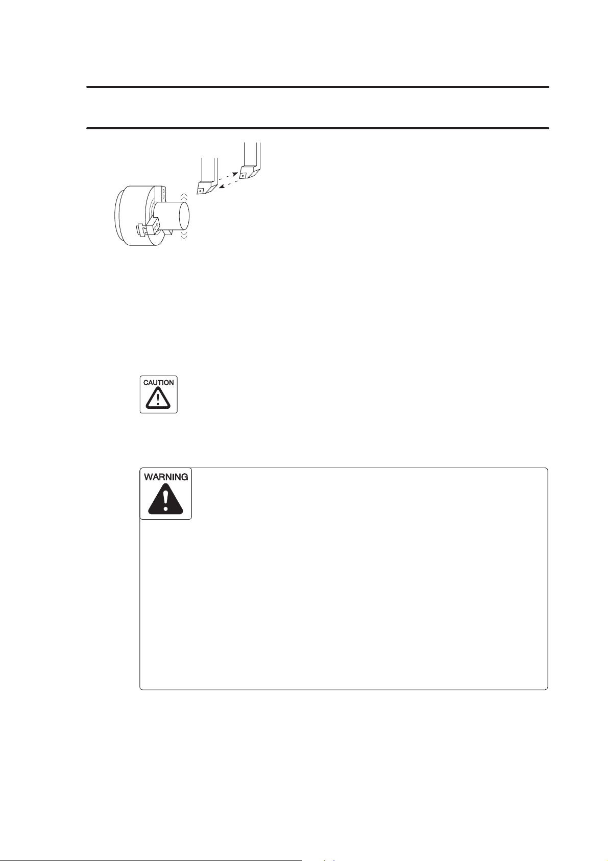
G FUNCTIONS B–5
2. G00 Positioning the Cutting Tool at a Rapid Traverse Rate
By specifying the G00 command, all axis
movement commands are executed at the rapid
traverse rate. In other words, the cutting tool is
positioned at the programmed target point at a
rapid traverse rate.
The G00 mode is usually used for the following operations:
1) At the start of machining:
To move the cutting tool close to the workpiece.
2) During machining:
To move the cutting tool, retracted from the workpiece, to the next programmed target
point.
When moving the cutting tool at a rapid traverse rate during machining, make
sure that there are no obstacles in the tool paths.
3) At the end of machining:
To move the cutting tool away from the workpiece.
When setting the G00 mode approach to the workpiece, determine
the approach paths carefully, taking the workpiece shape and
cutting allowance into consideration. The approach point in the
Z-axis direction should be more than “chucking allowance +
10 mm” away from the workpiece end face.
When the spindle is rotating, centrifugal force acts on the chuck
jaws, reducing the chuck gripping force. This can cause the
workpiece to come out of the chuck.
Unless the approach point is at least “chucking allowance + 10 mm”
away from the workpiece end face, the cutting tool could strike the
workpiece while moving at the rapid traverse rate if the workpiece
does come out of the chuck, or if there is a large amount of material
to be removed. This could cause accidents involving serious
injuries or damage to the machine.
Page 78

B–6 G FUNCTIONS
COMMAND
G00 X(U)_ Z(W)_ ;
D G00 Calls positioning at a rapid traverse rate.. . . . . . . . .
D X, Z Specifies the positioning target point at a rapid traverse. . . . . . . . .
rate.
The coordinates are specified in absolute values.
D U, W Specifies the positioning target point.. . . . . . . . .
The coordinates are specified in incremental values in
reference to the present position.
1 If X- and Z-axis movements are specified in the same block in the G00
mode, the tool path is not always a straight line from the present position to
the programmed end point. Make sure that there are no obstacles in the
tool path, remembering that X- and Z-axis movement is at the rapid
traverse rate. If the workpiece, fixture or tailstock (if featured) lies in the
tool path, it could interfere with the tool, tool holder, or turret head.
Depending on the workpiece holding method, there could also be
interference with the chuck and chuck jaws. This interference will damage
the machine.
Page B–9
2 For center-work, move the Z-axis first and then the X-axis to position the
cutting tool at the approach point.
In the cutting tool retraction operation, retract the cutting tool in the X-axis
direction first to a point where continuing cutting tool movement does not
result in interference with the tailstock. After that, move the Z-axis to the
required retraction position. (Applies only to machines equipped with a
tailstock.)
Page B–9
Page 79

G FUNCTIONS B–7
1 Once the G00 command is specified, it remains valid until another G code in
the same group is specified. G01, G02, and G03 are examples of G codes
which belong to the same group.
G codes which remain valid until another G code in the same group is specified
are called modal G codes.
For the G code groups, refer to page B–1 (1.).
2 The maximum rapid traverse rate varies among the machine models.
Page D–25 (3.4)
3 The rapid traverse rate is adjustable by using the rapid traverse rate override
switch on the machine operation panel.
4 If the rapid traverse rate override switch is set to “0” during automatic
operation, the programmed rapid traverse is not executed and the operation
enters the feed hold mode.
5 In a block where a T code is specified, G00 should be specified.
This G00 command is necessary to determine the cutting tool movement
feedrate to execute offset motion.
6 With the SL-400 and SL-600 series machines, if a T code is specified with G00
in the same block, the direction of the axis movement is automatically judged
whether it is away from or toward the workpiece from the remaining axis
movement distance. If the axis is going to move toward the workpiece, the
machine stops with an alarm message (No. 1320) displayed on the screen.
Page 80

B–8 G FUNCTIONS
Programming using G00
25
M60 P=2
C1.5
C1
5
5
2
1
4
3
6
∅ 54
O0001;
N1;
G50 S2000;
G00 T0101;
G96 S200 M03;
X56.0 Z20.0 M08; Positioning at
1
the cutting tool close to the workpiece
G01 Z0 F1.0; Positioning at 2 at a cutting feedrate, the start. . . . . . . . . . . . . . . . . . . . . .
point of facing
X30.0 F0.15;
G00 X50.0 W1.0; Positioning from
execute O.D. cutting
G01 X54.0 Z–1.0;
Z–5.0;
X56.8;
X59.8 Z–6.5;
Z–23.0 F0.2;
G00 U1.0 Z20.0; Positioning at
5
from the workpiece at a rapid traverse rate
X200.0 Z150.0 M09; Positioning at
6
rotated
M01;
Rapid traverse
Cutting feed
at a rapid traverse rate to move. . . . . . . . . . . . . . . . . .
to 4 at a rapid traverse rate to. . . . . . . . . . . . . . . . . .
3
to move the cutting tool away. . . . . . . . . . . . . . . . . . .
where the turret head can be. . . . . . . . . . . . . . . .
The G00 mode is used to move the cutting tool close to and away from the
workpiece.
Page 81

If X- and Z-axis movements are specified in the same block in the G00 mode,
the tool path is not always a straight line from the present position to the
programmed end point. Make sure that there are no obstacles in the tool path,
remembering that X- and Z-axis movement is at the rapid traverse rate. If the
workpiece, fixture or tailstock (if featured) lies in the tool path, it could interfere
with the tool, tool holder, or turret head. Depending on the workpiece holding
method, there could also be interference with the chuck and chuck jaws. This
interference will damage the machine.
G00 X(U)_ Z(W)_ ;
If the rapid traverse rates of X-axis and Z-axis are:
X-axis 18000 mm/min
Z-axis 24000 mm/min
G FUNCTIONS B–9
The tool path generated by the simultaneous movement
of the two axes in the G00 mode is shown in the illustration.
Z (24000)
Therefore, the tool paths are generated as illustrated below depending on the positional
relationship between the start and target points.
Start point
Start point
Programmed
target point
Programmed
target point
For center-work, move the Z-axis first and then the X-axis to position the cutting
tool at the approach point.
X
(18000)
In the cutting tool retraction operation, retract the cutting tool in the X-axis
direction first to a point where continuing cutting tool movement does not result
in interference with the tailstock. After that, move the Z-axis to the required
retraction position. (Applies only to machines equipped with a tailstock.)
1
2
Page 82

B–10 G FUNCTIONS
3. G01 Moving the Cutting Tool Along a Straight Path at a Cutting Feedrate
By specifying the G01 command, the cutting tool is
moved along a straight line to cut a workpiece.
The feedrate is specified with an F code by the
distance the cutting tool should be moved while the
spindle rotates one turn, or the distance to be
moved in a minute.
COMMAND
G01 X(U)_ Z(W)_ F_ ;
D G01 Calls the linear interpolation mode.. . . . . . . . .
D X, Z Specifies the cutting target point.. . . . . . . . .
The coordinates are specified in absolute values.
D U, W Specifies the cutting target point (distance and direction).. . . . . . . . .
The coordinates are specified in incremental values in
reference to the present position.
D F Specifies the feedrate in ordinary control. . . . . . . . . . . .
D In the G99 mode, the feedrate is specified in “mm/rev”.
F0.2 0.2 mm/rev. . . . . .
D In the G98 mode, the feedrate is specified in
“mm/min”.
F200 200 mm/min. . . . .
1 Once the G01 command is specified, it remains valid until another G code in
the same group is specified. G00, G02, and G03 are examples of G codes
which belong to the same group.
G codes which remain valid until another G code in the same group is specified
are called modal G codes.
For the G code groups, refer to page B–1 (1.).
2 The cutting feedrate is adjustable by using the feedrate override switch on the
machine operation panel in the range of 0 to 150%.
3 The feedrate data is “0” until an F code is specified.
If an axis movement command is read before an F code is specified, the
machine does not operate. In this case, an alarm message (No. 011) is
displayed on the screen.
4 When the power is turned on, the NC is in the G99 (feed per revolution) mode.
Page 83

Programming using G01
G FUNCTIONS B–11
To move the cutting tool at a cutting feedrate along the paths
³ 6 ³ 7 ³ 8 ³ 9.
5
25
M60 P=2
9
C1.5
5
8
7
5
6
C1
3
∅ 54
10
2
4
O0001;
N1;
G50 S2000;
G00 T0101;
G96 S200 M03;
X56.0 Z20.0 M08; Positioning at
at a rapid traverse rate to move. . . . . . . . . . . . . . . . . .
1
the cutting tool close to the workpiece
G01 Z0 F1.0; Positioning at
at a cutting feedrate, the start. . . . . . . . . . . . . . . . . . . . . .
2
point of facing
X30.0 F0.15; Facing at a feedrate of 0.15 mm/rev. . . . . . . . . . . . . . . . . . . . . .
G00 X50.0 W1.0; Positioning from
to 4 at a rapid traverse. . . . . . . . . . . . . . . . . .
3
rate, the start point of O.D. machining at a rapid
traverse rate
G01 X54.0 Z–1.0; Cutting along path
0.15 mm/rev
Z–5.0; Cutting along path
0.15 mm/rev
X56.8; Cutting along path 6³ 7 at a feedrate of . . . . . . . . . . . . . . . . . . . . . . . . . . . .
0.15 mm/rev
X59.8 Z–6.5; Cutting along path
0.15 mm/rev
Z–23.0 F0.2; Cutting along path
0.2 mm/rev
G00 U1.0 Z20.0; Positioning at
10
at a rapid traverse rate to move. . . . . . . . . . . . . . . . . . .
the cutting tool away from the workpiece
X200.0 Z150.0 M09; Positioning at
where the turret head can be. . . . . . . . . . . . . . . .
11
rotated
M01;
³ 3, and 4 ³
2
1
³ 5at a feedrate of . . . . . . . . . . . . . . . . . .
4
³ 6at a feedrate of . . . . . . . . . . . . . . . . . . . . . . . . . . . .
5
³ 8at a feedrate of . . . . . . . . . . . . . . . . . . . . . .
7
³ 9at a feedrate of . . . . . . . . . . . . . . . . . . . . . .
8
11
Rapid traverse
Cutting feed
Page 84

B–12 G FUNCTIONS
4. G02, G03 Moving the Cutting Tool Along Arcs at a Cutting Feedrate
By specifying the G02, G03 command, the cutting
tool is moved along an arc to cut a workpiece.
COMMAND
G02(G03) X(U)_ Z(W)_ R_ F_ ;
G02(G03) X(U)_ Z(W)_ I_ K_ F_ ;
D G02 Calls the circular interpolation . . . . . . . . .
mode in the clockwise direction.
D G03 Calls the circular interpolation . . . . . . . . .
mode in the counterclockwise direction.
D X, Z Specifies the end point of the arc.. . . . . . . . .
The coordinates are specified in absolute values.
D U, W Specifies the end point of the arc (distance and direction).. . . . . . . . .
The coordinates are specified in incremental values in
reference to the present position.
D R Specifies the radius of the arc.. . . . . . . . . . . .
D I Specifies the distance and the direction from the start point. . . . . . . . . . . . .
of the arc to the center of the circle in the X-axis direction.
The value should be specified as a radius.
D K Specifies the distance and the direction from the start point. . . . . . . . . . . .
of the arc to the center of the circle in the Z-axis direction.
D F Specifies the feedrate in ordinary control. . . . . . . . . . . .
D In the G99 mode, the feedrate is specified in “mm/rev”.
F0.2 0.2 mm/rev. . . . . .
D In the G98 mode, the feedrate is specified in
“mm/min”.
F200 200 mm/min. . . . .
G02
G03
1 If an R command and a pair of I and K commands are specified in the same
block, the R command is given priority and the I and K commands are ignored.
2 For the arc whose central angle is larger than 180_, an R command cannot be
used.
In this case, use I and K commands to define the arc.
3 When I and K commands are used to specify the distance and direction to the
center of an arc while X and Z commands are omitted or the start and end
points lie at the same position, a full circle (360_) is defined. If an R command
is used instead of I and K commands, no axis movement results.
Page 85
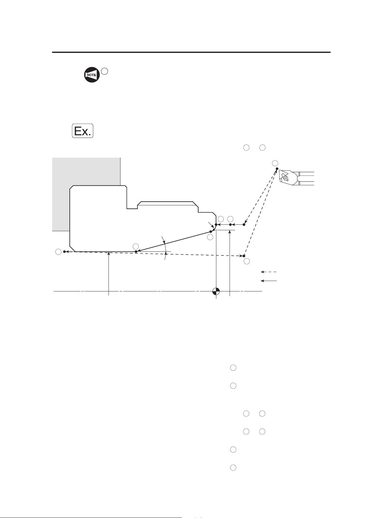
G FUNCTIONS B–13
4 To cut a half-circle accurately or to accurately define the center of an arc of
which the center angle is close to 180_, use I and K commands instead of an R
command.
If an R command is used, there are cases that the center of a half-circle or an
arc of which the center angle is close to 180_ cannot be set accurately due to
calculation error.
Programming using G02 or G03
To move the cutting tool at a cutting feedrate along the arc
R2
3
5
4
∅ 32
15°
1
2
∅ 44
³ 3.
2
6
7
Rapid traverse
Cutting feed
O0001;
N1;
G50 S2000;
G00 T0101;
G96 S200 M03;
X47.069 Z20.0 M08;
G01 Z1.0 F1.0; Positioning at
to move the cutting tool close to. . . . . . . . . . . . . . . . . . . .
1
the workpiece
Z0 F0.2; Positioning at
at a feedrate of 0.2 mm/rev. . . . . . . . . . . . . . . . . . . . . . . . . .
2
G02 X43.205 Z–1.482 R2.0 F0.07; Cutting an arc of 2 mm radius in the clockwise. . .
direction at a feedrate of 0.07 mm/rev
G01 X32.0 Z–22.392; Cutting along path
³ 4 at a feedrate of . . . . . . . . . . . . . . .
3
0.07 mm/rev
Z–41.0 F0.1; Cutting along path 4 ³ 5 at a feedrate of . . . . . . . . . . . . . . . . . . . . . .
0.1 mm/rev
G00 U–1.0 Z20.0; Positioning at
at a rapid traverse rate to move. . . . . . . . . . . . . . . . . .
6
the cutting tool away from the workpiece
X200.0 Z150.0 M09; Positioning at
where the turret head can be. . . . . . . . . . . . . . . .
7
rotated
M01;
Page 86

B–14 G FUNCTIONS
5. G50 Setting the Spindle Speed Limit
The spindle speed limit for an automatic operation
is set with the G50 command.
If the programmed spindle speed is faster than the
limit value set in the G50 block, actual spindle
speed is clamped at the set limit speed.
1 The spindle speed limit set using G50 must be no higher than
the lowest of the individual allowable speed limits for the
chuck, fixture, and cylinder. If you set a higher speed the
workpiece will fly out of the machine, causing serious injuries
or damage to the machine.
2 In the G96 (constant surface speed control) mode, the spindle
speed increases as the cutting tool approaches the center of
the spindle.
Near the center of the spindle, the spindle speed will reach the
allowable maximum speed of the machine. At this speed, the
chuck gripping force, cutting force, and centrifugal force cannot
be balanced to hold the workpiece securely in the chuck. As a
result, the workpiece will fly out of the machine, causing
serious injuries or damage to the machine.
The spindle speed limit must always be specified in a part
program by using the G50 command in a block preceding the
G96 block, in order to clamp the spindle speed at the specified
speed.
Page 87

COMMAND
G FUNCTIONS B–15
G50 S_ ;
D G50 Calls the mode to specify the spindle speed limit for. . . . . . . . .
automatic operation.
–1
D S Specifies spindle speed limit (min
1 The setting of the spindle speed override switch (if there is one)
is valid even when a spindle speed limit is set using G50.
If the switch is set to 110% or 120%, for example, the
programmed spindle speed will be overridden in accordance
with this setting. If this causes the actual spindle speed to
exceed the allowable speed of the chuck, fixture, or cylinder,
the workpiece will fly out of the chuck during machining,
causing serious injuries or damage to the machine.
Therefore, the spindle speed override switch must be set at
100% or lower.
).. . . . . . . . . . . .
2 When a G97 speed command is used in a program,
specification of the maximum speed with a G50 command will
be ignored. Therefore, when specifying the spindle speed with
a G97 command, specify a speed no higher than the lowest
speed among the allowable speed limits for the chuck, fixture,
and cylinder. If you set a higher speed the workpiece will fly
out of the machine, causing serious injuries or damage to the
machine.
An alarm message (No. 245) is displayed on the screen if a T command is
specified in the G50 block.
Page 88

B–16 G FUNCTIONS
Programming using G50 (Setting the spindle speed limit)
To move the cutting tool at a cutting feedrate along the path
25
∅ 54
C1
5
5
2
4
3
M60 P=2
C1.5
O0001;
N1;
G50 S2000; Setting the spindle speed limit for automatic. . . . . . . . . . . . . . . . . . . . . . .
operation at 2000 min
G00 T0101;
G96 S200 M03; Starting the spindle or spindle 1 in the normal. . . . . . . . . . . . . . . . . . . .
direction; surface speed is 200 m/min
The spindle speed is controlled to maintain the
surface speed constant at 200 m/min.
X56.0 Z20.0 M08; Positioning at
at a rapid traverse rate to move. . . . . . . . . . . . . . . . . .
1
the cutting tool close to the workpiece
G01 Z0 F1.0; Positioning at
at a cutting feedrate, the start. . . . . . . . . . . . . . . . . . . . . .
2
point of facing
X30.0 F0.15; Facing at a feedrate of 0.15 mm/rev. . . . . . . . . . . . . . . . . . . . . .
In order to maintain the surface speed constant,
the spindle speed increases as the cutting tool
moves closer to the workpiece center to reach the
allowable maximum speed of the machine.
However, since spindle speed limit is set at
–1
2000 min
in the “G50 S2000”, the spindle speed
does not exceed this limit value.
G00 X50.0 W1.0;
G01 X54.0 Z–1.0;
... ... ...
³ 3to execute facing.
2
6
1
Rapid traverse
Cutting feed
–1
Machining program
G00 U1.0 Z20.0;
X200.0 Z150.0 M09;
M01;
Page 89
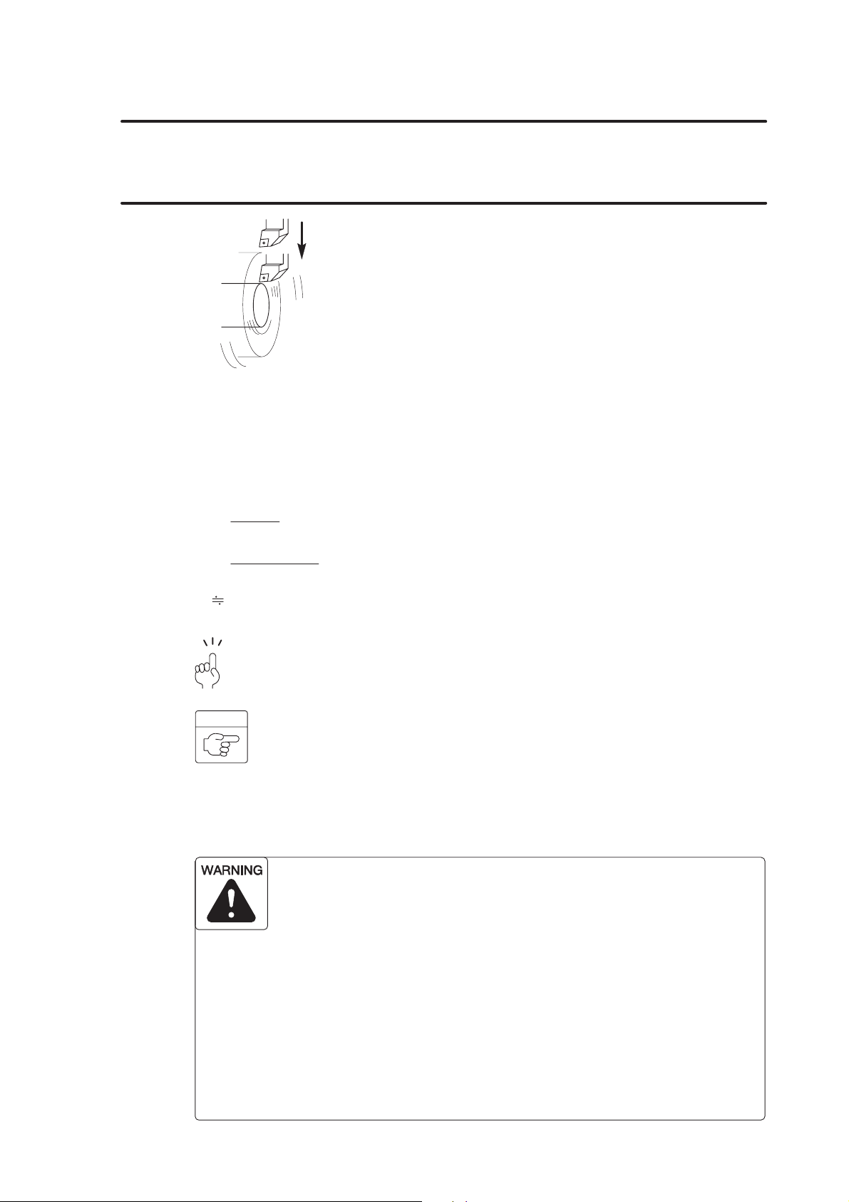
G FUNCTIONS B–17
6. G96 Controlling Spindle Speed to Maintain Surface Speed Constant
The G96 command is used to maintain surface
speed constant at the specified value.
The surface speed is also called the cutting speed.
It indicates the distance the cutting tool moves
along the workpiece surface (periphery) per
minute.
When the surface speed is specified with the G96
command, the spindle speed is automatically
controlled to maintain the surface speed constant
as the cutting diameter varies. This mode is used
to maintain the cutting conditions constant.
For example, if the cutting speed (V) is specified at 100 m/min to cut a 30 mm diameter
(D) workpiece, the spindle speed (N) is calculated as indicated below.
1000V
N =
π@D
1000 100
N =
Therefore, the spindle rotates at 1061 min
3.14 30
1061 min
Generally, the standard cutting speed is determined according to the material of the
workpiece and the cutting tool, the workpiece shape, and the chucking method.
COMMAND
–1
G96 S_ M03(M04);
D G96 Calls the constant surface speed control mode.. . . . . . . . .
D S Specifies the cutting speed (m/min).. . . . . . . . . . . .
D M03(M04) Specifies spindle or spindle 1 rotation in the normal. . . .
(reverse) direction.
In the G96 (constant surface speed control) mode, the spindle
speed increases as the cutting tool approaches the center of the
spindle.
Near the center of the spindle, the spindle speed will reach the
allowable maximum speed of the machine. At this speed, the chuck
gripping force, cutting force, and centrifugal force cannot be
balanced to hold the workpiece securely in the chuck. As a result,
the workpiece will fly out of the machine, causing serious injuries or
damage to the machine.
The spindle speed limit must always be specified in a part program
by using the G50 command in a block preceding the G96 block, in
order to clamp the spindle speed at the specified speed.
–1
.
Page 90
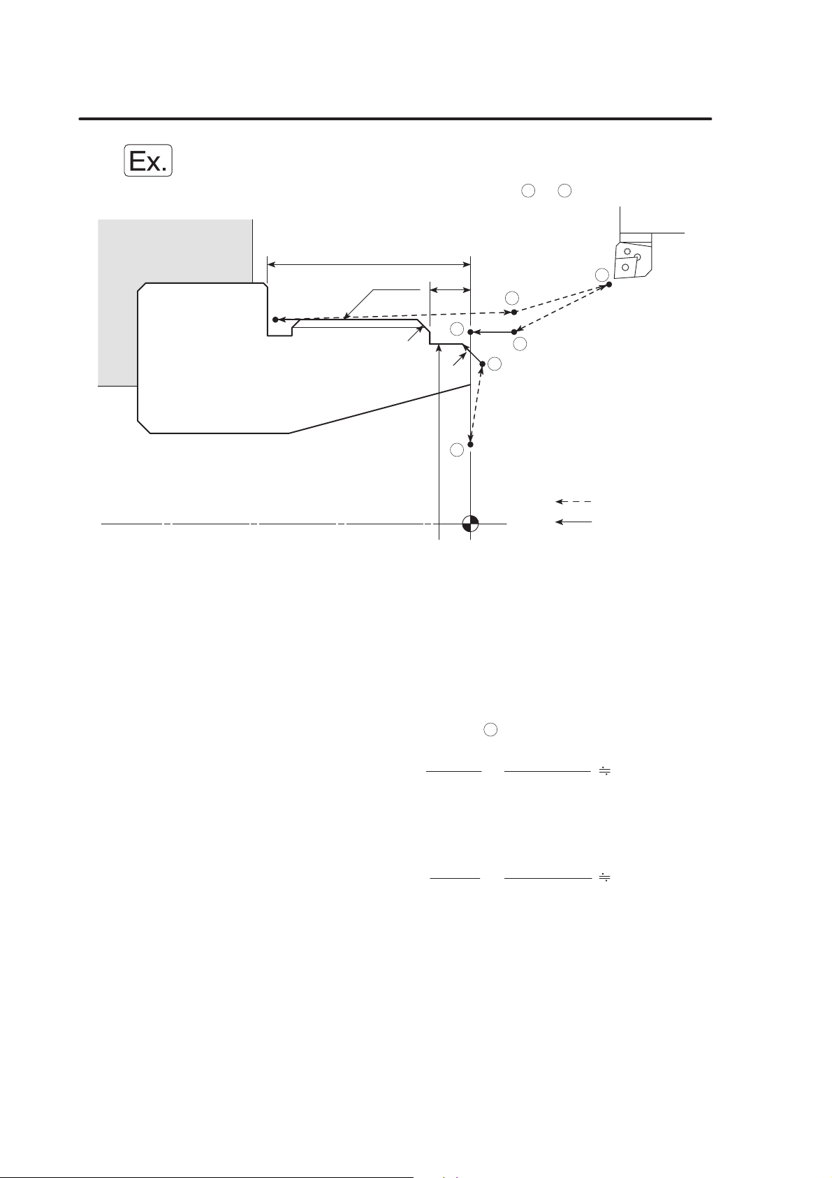
B–18 G FUNCTIONS
Programming using G96
To move the cutting tool at a cutting feedrate along the path 2 ³ 3 to execute facing.
25
M60 P=2
C1.5
C1
5
5
2
1
4
3
6
O0001;
N1;
G50 S2000; Setting the spindle speed limit for automatic. . . . . . . . . . . . . . . . . . . . . . .
G00 T0101;
G96 S200 M03; Starting the spindle or spindle 1 in the normal. . . . . . . . . . . . . . . . . . . .
X56.0 Z20.0 M08; Positioning at 1at a rapid traverse rate to move. . . . . . . . . . . . . . . . . .
G01 Z0 F1.0;
X30.0 F0.15; Facing at a feedrate of 0.15 mm/rev. . . . . . . . . . . . . . . . . . . . . .
G00 X50.0 W1.0;
G01 X54.0 Z–1.0;
...
Machining program
∅ 54
operation at 2000 min
–1
Rapid traverse
Cutting feed
direction; surface speed is 200 m/min
The spindle speed is controlled to maintain the
surface speed constant at 200 m/min.
the cutting tool close to the workpiece
1000V
N = =
π@D
1000 200
3.14 56
1137 (min–1)
At this position, the spindle or spindle 1 rotates at
1137 min–1 in the normal direction.
1000V
N = =
π@D
1000 200
3.14 30
2123 (min–1)
At this position, the spindle or spindle 1 should
–1
rotate at 2123 min
to provide the surface speed
of 200 m/min. However, since the spindle speed
–1
limit of 2000 min
is set in the “G50 S2000”, the
spindle speed does not exceed this limit value.
G00 U1.0 Z20.0;
X200.0 Z150.0 M09;
M01;
Page 91

G FUNCTIONS B–19
7. G97 Controlling Spindle Speed at Constant Speed
The G97 command is used to call the mode in
which a constant spindle speed is maintained.
During automatic operation, the spindle rotates at
the programmed speed.
1000V
N =
π@D
N: Spindle speed (min
V: Cutting speed (m/min)
D: Cutting diameter (mm)
π: Circumference constant
The G97 command must be specified for thread cutting operation and turning drilling
operation at the center of workpiece end face.
During thread cutting operation, the thread is cut gradually by changing the cutting
diameter for each thread cutting path while maintaining the start point of the thread.
Therefore, if the spindle speed is not kept constant, the start point shifts in each
thread cutting cycle making thread cutting impossible or tipping the tool nose.
–1
)
The G97 mode is also specified for carrying out copy turning on straight bar
workpiece.
COMMAND
G97 S_ M03(M04);
D G97 Calls the constant spindle speed command mode.. . . . . . . . .
D S Specifies the spindle speed (min
D M03(M04) Specifies spindle or spindle 1 rotation in the normal. . . .
(reverse) direction.
When a G97 speed command is used in a program, specification of
the maximum speed with a G50 command will be ignored.
Therefore, when specifying the spindle speed with a G97 command,
specify a speed no higher than the lowest speed among the
allowable speed limits for the chuck, fixture, and cylinder. If you set
a higher speed the workpiece will fly out of the machine, causing
serious injuries or damage to the machine.
–1
).. . . . . . . . . . . .
Page 92

B–20 G FUNCTIONS
When the spindle speed control mode is switched from the G96 mode to the G97
mode, if no spindle speed is specified in the G97 block, the spindle speed obtained
in the block immediately preceding the G97 block is used as the spindle speed for
the G97 mode operation.
Therefore, if no spindle speed is specified in the G97 block, the spindle speed for
the G97 mode will depend on the position of the cutting tool in the block preceding
the G97 block, and this could adversely affect machining accuracy and shorten the
life of the tool.
When switching the spindle speed control mode to the G97 mode, always specify a
spindle speed.
Page 93
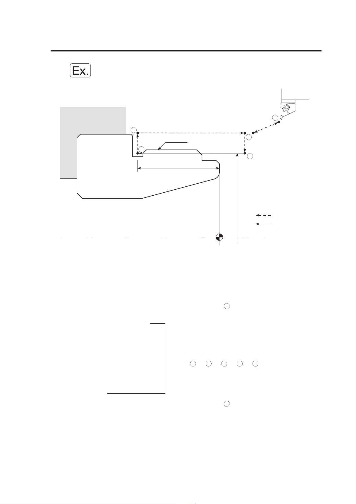
Programming using G97
To execute O.D. thread cutting
4
3
M60 P=2
24
∅ 57.4
G FUNCTIONS B–21
5
1
2
Rapid traverse
Cutting feed
O0001;
N1;
G00 T0101;
G97 S640 M03; Starting the spindle or spindle 1 at 640 min
normal direction
X70.0 Z20.0 M08;
G01 Z5.0 F1.0 M24; Positioning at
, the start point of the G92 thread. . . . . . . . . . . . . . . .
1
cutting cycle.
G92 X59.4 Z–24.0 F2.0;
X58.9;
X58.5;
X58.1; Execution of the G92 thread cutting cycle. . . . .
X57.8; (
1
³ 2 ³ 3 ³ 4 ³ 1 )
X57.56;
X57.36;
X57.26;
G00 X200.0 Z150.0 M09; Positioning at
where the turret head can be. . . . . . . . . . .
5
rotated
M05;
M30;
–1
in the. . . . . . . . . . . . . . . . . . . .
Page 94

B–22 G FUNCTIONS
8. G04 Suspending Program Execution (Dwell)
The G04 command is used to suspend program
execution during automatic operation for the period
specified in the program.
This function is called the dwell function, and is
used in operation such as the grooving operation.
If dwell is specified at the bottom of the groove, the
tool stops moving. The spindle keeps rotating
while the tool stays at the bottom of the groove.
By rotating the spindle one turn while locating the tool at the bottom of the groove, the
groove profile accuracy is improved and uncut portion is eliminated. The dwell function is
also used for opening and closing the chuck when the machine is equipped with the air
blow, the bar feeder or the loader.
When executing a dwell using the G04 command, if the cutting tool is kept in
contact with the workpiece at a position such as the bottom of a groove for a long
time it will shorten the life of the tool nose as well as adversely affecting machining
accuracy.
COMMAND
G04 X_ ;
G04 U_ ;
G04 P_ ;
D G04 Calls the dwell function.. . . . . . . . .
D X, U Specifies the period in which the program execution is. . . . . . . . .
suspended. The dwell period should be specified in units
of seconds with a decimal point.
X1.0 (U1.0) 1 sec. . .
X1 (U1) 0.001 sec. . . . . .
D P Specifies the period in which the program execution is. . . . . . . . . . . .
suspended. The dwell period should be specified in units
of 0.001 second without a decimal point.
P1000 1 sec. . . . . . .
1 A decimal point cannot be used when address P is used.
Dwell for 1.5 seconds G04 P1500;. . . . . . . .
Dwell for 2.3 seconds G04 P2300;. . . . . . . .
2 Programmable dwell period is 0.001 to 99999.999 seconds.
3 The dwell function is valid only in the specified block.
4 Dwell period per revolution of the spindle is calculated as follows:
t (sec) =
5 An alarm message (No. 245) is displayed on the screen if a T command is
specified in the G04 block.
60 (sec)
Spindle speed (min–1)
Page 95
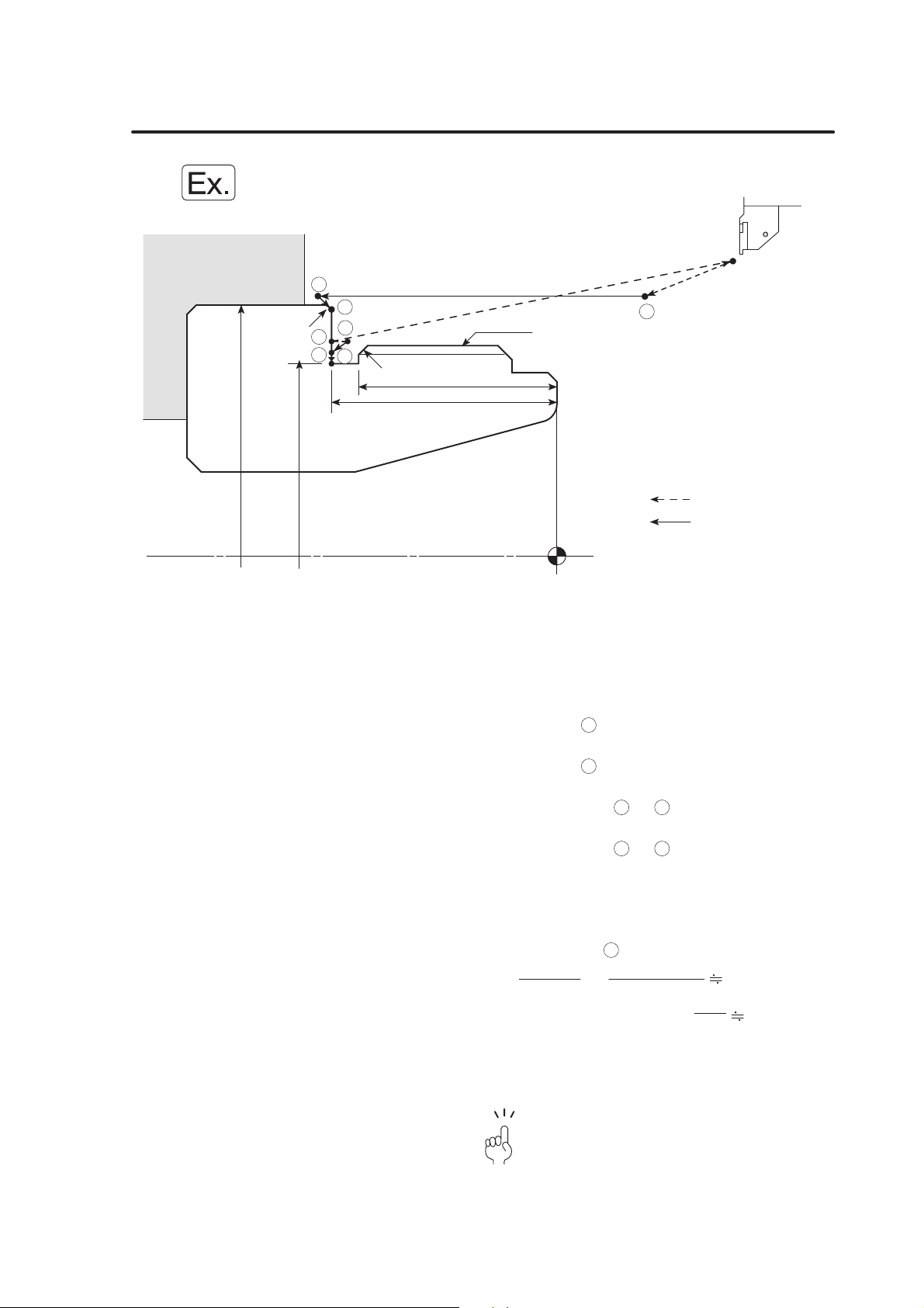
Programming using G04
To cut a 3 mm wide groove.
2
3
6
5
4
7
C1
∅ 69
C0.5
∅ 56
25
22
M60 P=2
G FUNCTIONS B–23
1
Rapid traverse
Cutting feed
O0001;
N1;
G50 S1500; Setting the spindle speed limit at 1500 min
automatic operation to ensure safety
G00 T0101;
G96 S100 M03; Starting the spindle or spindle 1 in the normal. . . . . . . . . . . . . . . . . . . .
direction at cutting speed of 100 m/min
X70.0 Z20.0 M08; Positioning at
to move the cutting tool close to. . . . . . . . . . . . . . . . . .
1
the workpiece at a rapid traverse rate
G01 Z–26.0 F1.0; Positioning at
, the start point of grooving at a. . . . . . . . . . . . . . . . . .
2
cutting feedrate
X68.0 Z–25.0 F0.07; Cutting along path
³ 3 at a feedrate of . . . . . . . . . . . . . . . .
2
0.07 mm/rev
X56.0 F0.1; Cutting along path
³ 4 at a feedrate of . . . . . . . . . . . . . . . . . . . . . . .
3
0.1 mm/rev
G04 U0.2; Suspending program execution for 0.2 seconds at. . . . . . . . . . . . . . . . . . . . . . . . .
the bottom of the groove to allow spindle to rotate
one turn
Spindle speed at
1000V
N = = 569 (min–1)
π@D
Period required for the
spindle to rotate one turn
4
1000 100
3.14 56
60
= 0.11 (sec)
569
–1
for. . . . . . . . . . . . . . . . . . . . . . .
G00 X60.8
...
M01;
To suspend program execution at the groove
bottom for more than one turn of the spindle, dwell
period is determined to 0.2 seconds.
The following program may be used instead
of “G04 U0.2;”
G04 X0.2; or G04 P200;
Machining program
Page 96

B–24 G FUNCTIONS
9. G98, G99 Setting Feedrate Units
Axis feedrate units are determined by specifying
the following two G codes:
G98
The G98 command calls the mode in which
axis feedrates specified by F codes are
interpreted in units of mm per minute. This
mode is used when the bar feeder, the pull-out
finger, or the rotary tool is used.
G99
The G99 command calls the mode in which
the axis feedrates specified by F codes are
interpreted in units of mm per revolution.
This mode is used for general turning
operations such as O.D. cutting, I.D. cutting,
and thread cutting.
In the G98 mode, the turret moves at the feedrate specified by the F code even
when the spindle is not rotating. Make sure that the cutting tool will not strike
the workpiece, etc., since this could damage the machine.
G98;
G01 Z_ F100.0; The cutting tool moves at a rate of 100 mm/min even . . . .
when the spindle is not rotating.
COMMAND
G98; Specifies the feedrate per minute (mm/min). . . . . .
G99; Specifies the feedrate per revolution (mm/rev). . . . . .
1 The G98 and G99 commands are modal.
Therefore, once the G98 command is specified, it remains valid until the G99
command is specified, or vice versa.
2 When the power is turned on, the G99 mode (feedrate per revolution) is set.
Page 97

Programming using G99
To execute O.D. cutting in the G99 mode
25
M60 P=2
C1.5
5
C1
G FUNCTIONS B–25
6
5
2
1
4
3
O0001;
N1;
(G99;) Since the G99 command is specified, the F codes. . . . . . . . . . . . . . . . . . . . . . . . . . . .
G50 S2000;
G00 T0101;
G96 S200 M03;
X56.0 Z20.0 M08;
G01 Z0 F1.0;
X30.0 F0.15;
G00 X50.0 W1.0;
G01 X54.0 Z–1.0;
Z–5.0;
X56.8;
X59.8 Z–6.5;
Z–23.0 F0.2;
G00 U1.0 Z20.0;
X200.0 Z150.0 M09;
M01;
∅ 54
Rapid traverse
Cutting feed
are interpreted in units of “mm/rev”.
Page 98

B–26 G FUNCTIONS
Programming using G98
To use the pull-out finger for bar machining operation in the G98 mode
The workpiece is pulled out of the chuck with the pull-out finger mounted in the turret head
while the spindle rotation is stopped.
Always specify an M05 command to stop spindle rotation before using a
pull-out finger or workpiece pusher, etc. If spindle rotation is not stopped the
machine could be damaged.
1
23
4
G98 (feedrate per minute)
G00 (rapid traverse)
O0001;
N1;
G00 T0101 M05;
X0 Z20.0 M09; Positioning at
workpiece
G98; Establishing the “mm/min” mode. . . . . . . . . . . . . . . . . . . . . . . . . . . . .
In the following blocks, the F codes are all
interpreted in the unit of “mm/min”.
G01 Z–60.0 F500; Positioning at
workpiece (bar stock)
M11; Unclamping of the chuck. . . . . . . . . . . . . . . . . . . . . . . . . . . . .
G04 U2.0; Dwell for 2 seconds to ensure unclamping of the. . . . . . . . . . . . . . . . . . . . . . . . .
chuck
The dwell period should be a little longer
than the time required for the chuck to
operate (open, close) to ensure safe
operation.
Z–10.0; Moving to
4
stock from the chuck
M10; Clamping of the chuck. . . . . . . . . . . . . . . . . . . . . . . . . . . . .
G04 U2.0; Dwell for 2 seconds to ensure clamping of the. . . . . . . . . . . . . . . . . . . . . . . . .
chuck
Rapid traverse
Cutting feed
at a rapid traverse rate to grip the. . . . . . . . . . . . . . . . . . . . .
2
at 500 mm/min to grip the. . . . . . . . . . . . . . . . . .
3
at 500 mm/min to pull out the bar. . . . . . . . . . . . . . . . . . . . . . . . . . .
The dwell period should be a little longer
than the time required for the chuck to
operate (open, close) to ensure safe
operation.
Page 99

G FUNCTIONS B–27
G00 Z20.0; Positioning at
the bar stock from the pull-out finger
X200.0 Z50.0; Positioning at
rotated
G99; Selecting the G99 (mm/rev) mode. . . . . . . . . . . . . . . . . . . . . . . . . . . . .
In the following blocks, the F codes are all
interpreted in the unit of “mm/rev”.
M01
N2;
(G99;)
G00 T0202;
G96 S120 M03;
... ... ...
Machining program
at a rapid traverse rate to release. . . . . . . . . . . . . . . . . . . . . . . .
2
where the turret head can be. . . . . . . . . . . . . . . . . . . . .
1
Page 100

B–28 G FUNCTIONS
10. G40, G41, G42 Automatic Tool Nose Radius Offset
The tool nose does not have a sharp edge but is
rounded as illustrated on the left. Therefore, the
point of the tool nose used for programming is
offset from the actual cutting point. The tool nose
radius offset function is used to eliminate
Programmed point
R
Actual cutting point
R: Tool nose radius
For details on the automatic tool nose radius offset (G40, G41 and G42), refer
to Chapter E, “AUTOMATIC TOOL NOSE RADIUS OFFSET”.
dimensional errors caused by this difference.
If taper or arc cutting is programmed without taking
into consideration the tool nose radius, overcut or
undercut will occur.
The G41 and G42 commands are specified in a
program to automatically eliminate this overcut or
undercut by offsetting for the tool nose radius.
COMMAND
G01(G00) G41 X_ Z_ F_ ;
G01(G00) G42 X_ Z_ F_ ;
G01(G00) G40 X_ Z_ I_ K_ F_ ;
D G01(G00) Calls the interpolation mode in which the tool nose radius. . . .
offset function is specified.
G00 Rapid traverse. .
G01 Cutting feed. .
D G41 Calls the tool nose radius offset (left) function.. . . . . . . . .
The tool position is offset to the left in reference to the tool
advancing direction.
D G42 Calls the tool nose radius offset (right) function.. . . . . . . . .
The tool position is offset to the right in reference to the
tool advancing direction.
D G40 Cancels the tool nose radius offset function.. . . . . . . . .
D X, Z Specifies the coordinate values of the end point.. . . . . . . . .
D I, K The direction of the workpiece shape defined in the. . . . . . . . . .
following block. The I and K commands are specified in
incremental values (I: in radius).
D F Specifies the feedrate. . . . . . . . . . . .
G42
Tool advancing direction
Tool advancing direction
Workpiece
G41
 Loading...