

Page 1

FOR SAFE OPERATION
Applicable Model
NC LATHES
(CE COMPATIBLE)
This FOR SAFE OPERATION describes fundamental safety information for safe
operation. Be sure to read this information before operating the machine.
And also, keep this FOR SAFE OPERATION carefully so that it will not be lost.
SO-CENL-H2EN
Page 2

• The contents of this manual are subject to change without notice due to
improvements to the machine or in order to improve the manual.
Consequently, please bear in mind that there may be slight discrepancies
between the contents of the manual and the actual machine. Changes to
the instruction manual are made in revised editions which are
distinguished from each other by updating the instruction manual number.
• Should you discover any discrepancies between the contents of the
manual and the actual machine, or if any part of the manual is unclear,
please contact Mori Seiki and clarify these points before using the
machine. Mori Seiki will not be liable for any damages occurring as a
direct or indirect consequence of using the machine without clarifying
these points.
• All rights reserved: reproduction of this instruction manual in any form, in
whole or in part, is not permitted without the written consent of Mori Seiki.
The product shipped to you (the machine and accessory
equipment) has been manufactured in accordance with the laws
and standards that prevail in the relevant country or region.
Consequently it cannot be exported, sold, or relocated, to a
destination in a country with different laws or standards.
The export of this product is subject to an authorization from the
government of the exporting country.
Check with the government agency for authorization.
990730
Page 3
SIGNAL WORD DEFINITION
A variety of symbols are used to indicate different types of warning information and advice.
Learn the meanings of these symbols and carefully read the explanation to ensure safe operation
while using this manual.
<Symbols related with warning>
The warning information is classified into three categories, DANGER, WARNING, and CAUTION.
The following symbols are used to indicate the level of danger.
DANGER
WARNING
CAUTION
Indicates a potentially hazardous situation which, if not avoided, may result in minor or
moderate injury or damages to the machine.
The information described following the caution symbol must be strictly observed.
<Other symbols>
NOTE
Indicates the items that must be taken into consideration.
Indicates an imminently hazardous situation which, if not avoided, will
result in death or serious injury.
The information described in the DANGER frame must be strictly
observed.
Indicates a potentially hazardous situation which, if not avoided, could
result in death or serious injury.
The information described in the WARNING frame must be strictly
observed.
Page 4

CONTENTS
1 FOR SAFE OPERATION . . . . . . . . . . . . . . . . . . . . . . . . . . . . . . . . . . . . . . . . . . . . . . . . P-1
2 DANGEROUSNESS OF MACHINE MODIFICATION . . . . . . . . . . . . . . . . . . . . . . . . . . P-3
3 CONSIDERATIONS BEFORE OPERATING THE MACHINE . . . . . . . . . . . . . . . . . . . . P-6
3-1 Before Using the Machine . . . . . . . . . . . . . . . . . . . . . . . . . . . . . . . . . . . . . . . . . . P-6
3-2 Before Operating the Machine . . . . . . . . . . . . . . . . . . . . . . . . . . . . . . . . . . . . . . P-12
4 FIRE PREVENTION . . . . . . . . . . . . . . . . . . . . . . . . . . . . . . . . . . . . . . . . . . . . . . . . . . . P-16
5 PRECAUTIONS ON MACHINE INSTALLATION . . . . . . . . . . . . . . . . . . . . . . . . . . . . . P-18
5-1 Installation Site. . . . . . . . . . . . . . . . . . . . . . . . . . . . . . . . . . . . . . . . . . . . . . . . . . P-18
5-2 Power Supply . . . . . . . . . . . . . . . . . . . . . . . . . . . . . . . . . . . . . . . . . . . . . . . . . . . P-19
5-3 Grounding . . . . . . . . . . . . . . . . . . . . . . . . . . . . . . . . . . . . . . . . . . . . . . . . . . . . . P-20
5-4 Air Supply. . . . . . . . . . . . . . . . . . . . . . . . . . . . . . . . . . . . . . . . . . . . . . . . . . . . . . P-20
5-5 Installation . . . . . . . . . . . . . . . . . . . . . . . . . . . . . . . . . . . . . . . . . . . . . . . . . . . . . P-21
5-6 Points to Check Before Turning ON the Power for the First Time . . . . . . . . . . . P-23
5-7 Points to Check After Turning ON the Power for the First Time. . . . . . . . . . . . . P-24
6 TURNING THE POWER ON AND OFF . . . . . . . . . . . . . . . . . . . . . . . . . . . . . . . . . . . . P-25
6-1 Before Turning the Power ON . . . . . . . . . . . . . . . . . . . . . . . . . . . . . . . . . . . . . . P-25
6-2 After Turning the Power ON . . . . . . . . . . . . . . . . . . . . . . . . . . . . . . . . . . . . . . . . P-26
6-3 When Turning the Power OFF . . . . . . . . . . . . . . . . . . . . . . . . . . . . . . . . . . . . . . P-27
7 SAFETY PRACTICES DURING SETUP . . . . . . . . . . . . . . . . . . . . . . . . . . . . . . . . . . . P-28
7-1 Safety Practices when Mounting/Removing a Chuck . . . . . . . . . . . . . . . . . . . . P-37
8 SAFETY PRACTICES WHEN CHUCKING A WORKPIECE . . . . . . . . . . . . . . . . . . . . P-39
9 SAFETY PRACTICES DURING MACHINE OPERATION . . . . . . . . . . . . . . . . . . . . . . P-45
10 SAFETY PRACTICES DURING PROGRAMMING . . . . . . . . . . . . . . . . . . . . . . . . . . . P-50
11 TO ENSURE HIGH ACCURACY . . . . . . . . . . . . . . . . . . . . . . . . . . . . . . . . . . . . . . . . . P-55
12 SAFETY PRACTICES DURING MAINTENANCE AND INSPECTION . . . . . . . . . . . . P-57
12-1 Daily Maintenance . . . . . . . . . . . . . . . . . . . . . . . . . . . . . . . . . . . . . . . . . . . . . . . P-57
12-2 Precautions When Performing Maintenance and Inspection Work . . . . . . . . . . P-58
12-3 Disposal of Industrial Waste. . . . . . . . . . . . . . . . . . . . . . . . . . . . . . . . . . . . . . . . P-62
13 PRECAUTIONS WHEN SELECTING COOLANT . . . . . . . . . . . . . . . . . . . . . . . . . . . . P-63
14 MACHINING CHAMBER OBSERVATION WINDOW. . . . . . . . . . . . . . . . . . . . . . . . . . P-65
Page 5

15 PRECAUTIONS ON INDUSTRIAL ROBOTS. . . . . . . . . . . . . . . . . . . . . . . . . . . . . . . . P-67
16 CAUTION LABELS ON THE MACHINE. . . . . . . . . . . . . . . . . . . . . . . . . . . . . . . . . . . . P-69
17 CAUTIONS RELATING TO SPINDLE SPEED. . . . . . . . . . . . . . . . . . . . . . . . . . . . . . . P-70
18 CAUTIONS RELATING TO THE RAPID TRAVERSE RATE . . . . . . . . . . . . . . . . . . . . P-71
19 CAUTIONS RELATING TO CENTER-WORK . . . . . . . . . . . . . . . . . . . . . . . . . . . . . . . P-72
20 CAUTIONS RELATING TO COORDINATE SYSTEM SETTING . . . . . . . . . . . . . . . . . P-73
21 CAUTIONS RELATING TO G CODES. . . . . . . . . . . . . . . . . . . . . . . . . . . . . . . . . . . . . P-74
22 CAUTIONS RELATING TO M CODES. . . . . . . . . . . . . . . . . . . . . . . . . . . . . . . . . . . . . P-75
Page 6

1 FOR SAFE OPERATION
This machine is intended for use by persons who have a basic knowledge of machine tools,
including cutting theory, tooling and fixtures. Mori Seiki cannot accept responsibility for accidents
that occur as a result of operation or maintenance of the machine by personnel who lack this basic
knowledge or sufficient training.
Workpiece materials and shapes vary widely among machine users. Mori Seiki cannot predict the
chucking pressure, spindle speed, feedrate, depth of cut, etc., that will be required in each case
and it is therefore the user's responsibility to determine the appropriate settings.
Each machine is shipped with a variety of built-in safety devices. However, careless handling of
the machine can cause serious accidents. To prevent the occurrence of such accidents, all
programmers and other personnel that deal with the machine must carefully read the manuals
supplied by Mori Seiki, the NC unit manufacturer, and equipment manufacturers, before
attempting to operate, maintain, or program the machine.
Because there are so many "things that cannot be done" and "things that must not be done" when
using the machine, it is impossible to cover all of them in the Instruction Manual. Assume that
something is impossible unless the manual specifically states that it can be done.
FOR SAFE OPERATION P-1
The following manuals are supplied with your NC lathe:
I. Instruction Manuals prepared by Mori Seiki
• MAINTENANCE MANUAL
(MAINTENANCE MANUAL, MAINTENANCE INFORMATION,
INSTALLATION MANUAL, DRAWINGS)
• Operation Manual
• Programming Manual
II. NC unit Operation and Maintenance Manuals prepared by the NC unit manufacturer
III. Instruction Manuals prepared by equipment manufacturers
In addition to these manuals, ladder diagrams, parameter tables and electrical circuit diagrams are
also supplied with the machine to help with electrical maintenance. The ladder diagrams are
provided in the document box, parameter tables and electrical circuit diagrams are stored in the
document compartment inside the electrical cabinet. Please make use of these materials when
carrying out maintenance work.
Fundamental safety information is presented in the following pages.
All cautions on operation must be strictly observed when operating the machine, carrying out
maintenance work, or writing programs. Failure to observe fundamental safety information can
cause accidents in which the operator or other personnel working near the machine are seriously
injured, or the machine is damaged. All personnel that deal with the machine must carefully read
and thoroughly understand the information in the following pages before attempting programming
or operating the machine.
The vocabulary and terms used for machine parts and operations in the warnings, cautions and
notes are defined or explained in the manual texts and illustrations.
If you are unsure of the meaning of any word or expression, please refer to the corresponding
textual explanation or illustration. If you still cannot understand or are unsure of the meaning,
contact Mori Seiki for clarification.
SO-CENL-H2EN
Page 7

P-2 FOR SAFE OPERATION
"Operator", as used in these cautions, means not only the operator who operates or supervises a
machine tool to perform machining, but also any person, including maintenance personnel who
maintain and inspect a machine tool or safety device or safety measures provided with it, and the
programmers who create programs used for machining, who are engaged in operations which
deal with a machine tool.
Therefore, all persons engaged in these operations must carefully read these cautions and related
materials, and thoroughly understand the contents before attempting to operate the machine.
SO-CENL-H2EN
Page 8
FOR SAFE OPERATION P-3
2 DANGEROUSNESS OF MACHINE MODIFICATION
WARNING
CAUTION
Examples of accidents which can occur if the machine specifications are changed, if the machine
is modified, or if the machine is operated or run with any of the safety devices (such as the door
interlock function) or protective covers or doors removed, are presented below.
The machine specifications are set before shipping so that the customer's
safety is ensured and the machine can deliver its full performance. Never
change the settings nor modify the machine in any case. Changing the
settings or modifying the machine without consultation may degrade
safety assurance or cause accidents involving serious injuries, impaired
machine performance, and considerable shortening of the machine
service life. If the specifications and/or settings have to be changed, or
the machine has to be modified to meet new machining requirements, or
due to changes in the operating conditions, consult Mori Seiki.
Mori Seiki cannot accept responsibility for any accident that occurs due to
the machine specifications being changed, or the machine being
modified, by the customer.
When changing machine parts that have broken or become faulty, or replacing
consumable parts that have been used for their service lives, be sure to use genuine
parts specified by Mori Seiki. The use of parts not specified by Mori Seiki will be
regarded as a modification and Mori Seiki will not accept responsibility for any accident
that occurs as a result of using such parts.
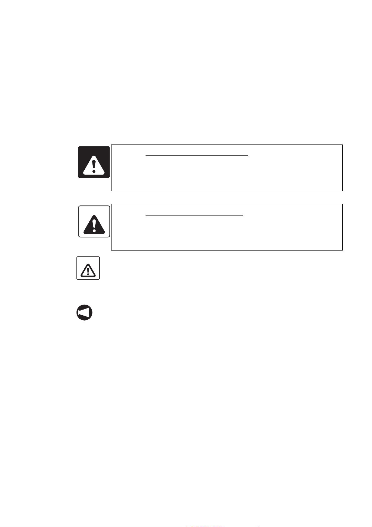
1. The operator will become entangled with
the spindle if the spindle starts while the
operator is touching the chuck or
workpiece.
2. The operator will become entangled with
the spindle if the operator touches the
chuck or the workpiece while the spindle
is rotating.
The accidents described above, in which the
operator becomes entangled with the rotating
parts of the machine, will result in serious injury
or death.
SO-CENL-H2EN
Page 9
P-4 FOR SAFE OPERATION
.
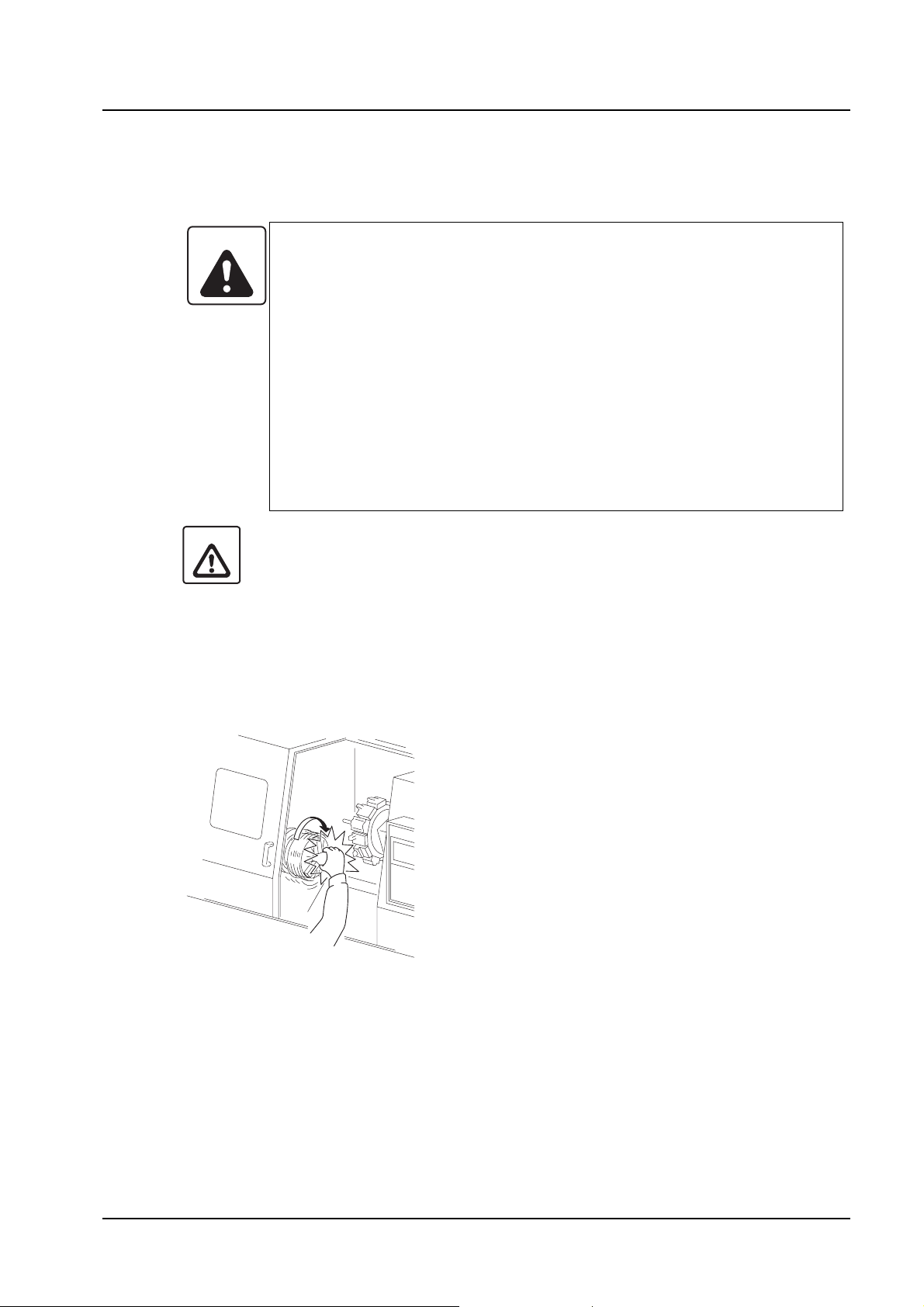
3. A workpiece will fly out if the spindle
rotation is started while the workpiece is
not clamped correctly.
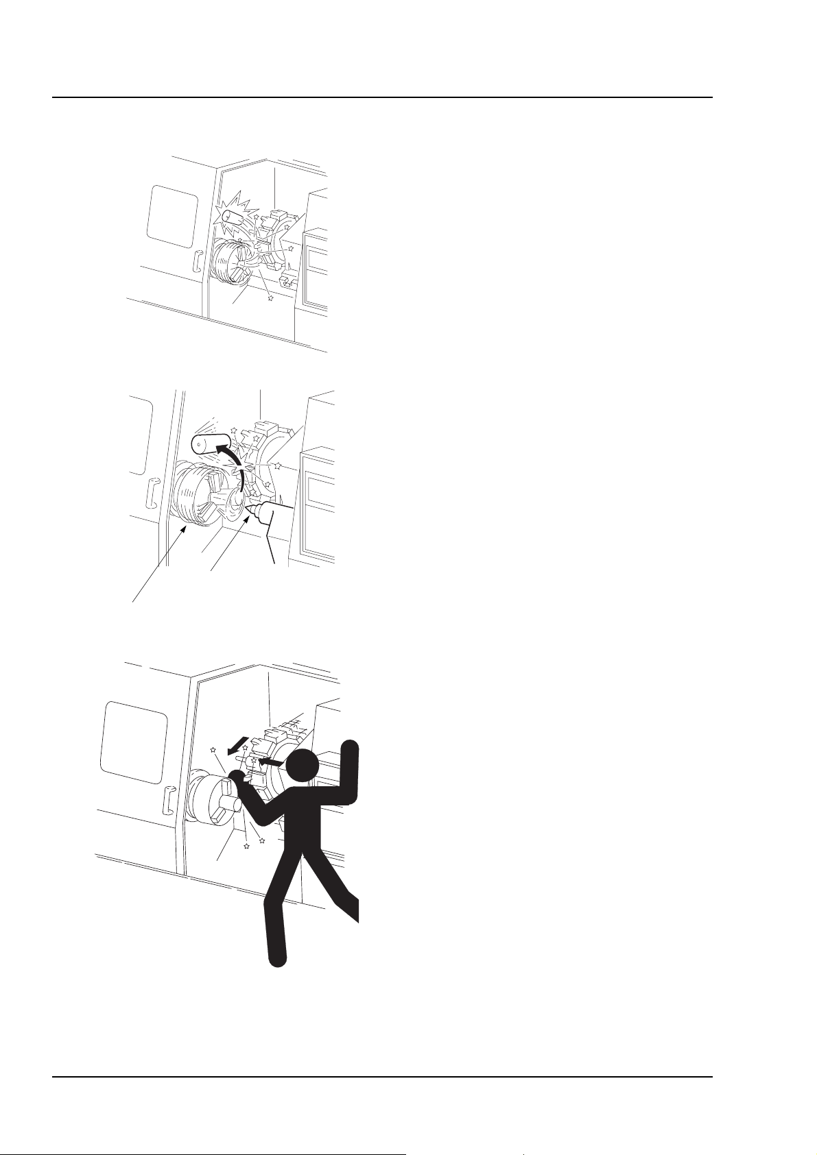
4. A workpiece and/or chuck jaw will fly out
if the cutting tool (turret) is hit against the
workpiece due to programming error.
5. A workpiece will fly out due to
excessively heavy cutting force or
lowered workpiece gripping force of the
chuck caused by centrifugal force.
6. The workpiece could fly out when
performing chuck work or center-work
since it is possible to start the spindle
and perform automatic operation even if
the chuck is unclamped.
7. The workpiece could fly out when
performing center-work since it is
possible to start the spindle and perform
automatic operation even if the
workpiece is not supported by the center.
Workpiece is not held by the
tailstock spindle.
Workpiece is not clamped by
the chuck correctly.
As described above, a workpiece or a chuck
jaw, disengaged from the chuck due to some
reason, flies out to hits the operator or a
person standing near resulting in serious injury
or death.
8. The operator will be caught or entangled
by moving parts such as turret during
axis feed or indexing motions, resulting
in serious injury or death.
SO-CENL-H2EN
Page 10
FOR SAFE OPERATION P-5
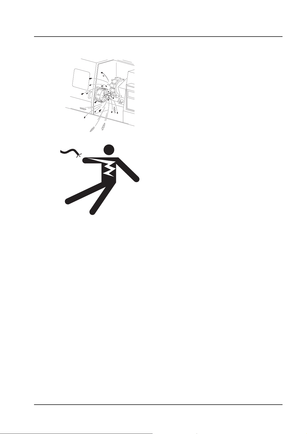
9. The operator or a person standing near
the machine will be splashed with chips
and coolant during machining, resulting
in injury or health problems (particularly if
chips or coolant get into the eyes).
10. It is possible to turn the power ON even
when the electrical cabinet door is open:
this means that the operator could touch
a live part inside the electrical cabinet
and sustain an electric shock, resulting in
serious injury or death.
SO-CENL-H2EN
Page 11
P-6 FOR SAFE OPERATION
3 CONSIDERATIONS BEFORE OPERATING THE MACHINE
The cautions that must constantly be born in mind when operating the machine are listed below.
3-1 Before Using the Machine
Listed below are important cautions that apply to all machine-related work (machine operation,
maintenance, inspection, programming, etc.).
DANGER
1. Never touch a switch, button, or key with wet hands.
If it is not properly grounded or is leaking current, you could receive
an electric shock.
2. Before starting machine operation, check that there is nobody inside
the protective cover or close to rotating or moving parts of the
machine. Never touch or stand near the rotating or moving parts of
the machine while it is operating; you could be seriously injured by
being entangled in the rotating parts or crushed by the moving parts.
3. Never operate the machine with the protective cover removed or
while interlocks or other safety devices are ineffective, since the
machine could operate in an unexpected manner, causing accidents
involving serious injuries.
Contact Mori Seiki, the NC unit manufacturer or relevant equipment
manufacturer immediately if the protective cover or safety devices
are damaged.
4. Always lock out the power to the machine before carrying out work
inside the machine – such as setup work or cleaning the inside of
the machine – and before carrying out inspections, repairs, or
maintenance work. In addition, set the main switch to the OFF
position and lock it, and place "PERSONNEL INSIDE MACHINE" or
"UNDER MAINTENANCE" signs around the machine to stop anyone
from switching on the power or operating the machine while the
work is in progress. If work inside the machine or inspection or
maintenance work is carried out with the power switched on,
machine elements could be moved, and the personnel carrying out
the work could be seriously injured by being entangled in the
rotating parts or crushed by the moving parts of the machine.
SO-CENL-H2EN
5. Always switch off the power before carrying out inspection or
maintenance work in the electrical cabinet or on motors and
transformers. If work has to be done while the power is switched on,
it must be carried out by a qualified electrical engineer, taking the
proper precautions; there is a danger of electric shock.
Page 12
FOR SAFE OPERATION P-7
DANGER
WARNING
6. Cover power supply cables that are run along the floor with rigid
insulated plates to prevent them from being damaged. Damage to
the insulation of the power supply cable could cause electric
shocks.
7. Even after the power is turned off, some devices will remain charged
and the temperature of motors, lights inside the machine, etc., will
remain high. Make sure that the charge has been discharged or the
temperature has fallen before carrying out maintenance work or
inspections on these devices. If you touch these devices/units
carelessly while they are still charged or while the temperature is
still high you could receive an electric shock or be burned.
8. Check that all cables are properly insulated before using the
machine. There is considerable danger of electric shock if damaged
cables are used.
1. Keep the floor area around the machine tidy and clean; do not leave
things lying on it, and clean up spilled water or oil immediately. If
you fail to do this, plant personnel may injure themselves by tripping
over or slipping on the floor.
2. Before operating the machine, check the area where you will have to
stand and walk to make sure you can operate the machine safely. If
you do not check your footing beforehand, you could loose your
balance while working and injure yourself by putting your hands in a
dangerous place while trying to find support, or by falling over.
3. Before using a switch, button, or key, check visually that it is the one
you intend to use, and then press or set it decisively. Pressing the
wrong switch, button, or key by mistake can cause accidents
involving serious injuries or damage to the machine.
4. Keep the doors closed during machine operation. Leaving the
machine running or operating it with doors open could cause
accidents involving serious injuries or damage to the machine; plant
personnel could be seriously injured by being entangled in the
rotating parts of the machine, crushed by its moving parts, struck by
broken tools, workpieces or jaws flying out of the machine, hit by
flying chips, or splashed with coolant.
5. The parameters are set on shipment in accordance with the machine
specifications; do not change them without first consulting Mori
Seiki. If the parameters are changed without consultation, the
machine may operate in an unexpected manner, causing accidents
involving serious injuries or damage to the machine.
SO-CENL-H2EN
Page 13

P-8 FOR SAFE OPERATION
WARNING
6. The machine specifications are set before shipping so that the
machine can deliver its full performance. Changing the settings
without consultation may lead to accidents involving serious
injuries, impaired machine performance, and considerable
shortening of the machine service life. If the specifications and/or
settings have to be changed or the machine has to be modified to
meet new machining requirements or due to changes in the
operating conditions, consult Mori Seiki.
7. Before operating or programming the machine, or performing
maintenance work, carefully read the instruction manuals provided
by Mori Seiki, the NC unit manufacturer and the equipment
manufacturers so that you fully understand the information they
contain. Keep these instruction manuals safely so that you do not
lose them. If you do lose an instruction manual, contact Mori Seiki,
the NC unit manufacturer, or the relevant equipment manufacturer. If
you attempt to operate the machine without having carefully read the
instruction manuals first, you will perform dangerous and erroneous
operations which may cause accidents involving serious injuries or
damage to the machine.
8. Always observe the instructions in the caution labels stuck to the
machine. Carefully read the Safety Guidelines supplied with the
machine so that you fully understand them. If the writing on the
labels becomes illegible, or if the labels are damaged or peel off,
contact Mori Seiki. Also contact Mori Seiki if you cannot understand
any of the labels. If you operate the machine without observing the
instructions on the labels, or without understanding them properly,
you will perform dangerous and erroneous operations which may
cause accidents involving serious injuries or damage to the
machine.
SO-CENL-H2EN
9. Never operate, maintain, or program the machine while under the
influence of alcohol or drugs. Your concentration will be impaired,
you may loose your balance and fall against dangerous parts of the
machine, and you may operate the machine incorrectly, causing
accidents involving serious injuries or damage to the machine.
10. Machine operators and authorized personnel working inside the
plant and in the vicinity of the machine must put their clothing and
hair in order so that there is no danger they will be entangled in the
machine. If you have uncontrolled long hair or loose clothing and it
gets caught in the machine, you will be seriously injured by being
entangled in the rotating parts of the machine or crushed by its
moving parts. Always wear safety shoes, eye protectors and a
helmet.
Page 14

FOR SAFE OPERATION P-9
WARNING
11. The machine is equipped with interlock functions such as the door
interlock, chuck interlock, tailstock spindle interlock (applies only to
machines equipped with a tailstock) and electrical cabinet door
interlock to ensure the operator's safety. All the interlock functions
must be ON when operating the machine. If you have to operate the
machine with the interlocks released, you must recognize that there
are many hazards involved and pay particular attention to safety
while operating the machine in this condition. After finishing the
necessary work, you must switch the interlocks back ON.
If the machine is operated with the interlocks released, it may
operate in an unexpected manner, causing accidents involving
serious injuries or damage to the machine.
12. The door interlock function serves only to protect the machine
operator from accidents that can be prevented by inhibiting manual
and automatic operation of the spindle, axis movement, and all other
operations in automatic operation when the door is opened and
while it is open; it will not afford protection against other hazards.
For example, each machine user will machine a variety of workpiece
types and use a variety of workpiece holding fixtures, cutting tools,
and cutting conditions; you are still responsible for ensuring safety
with regard to the hazards that can arise from these user-specific
conditions.
13. If the door interlock function is released, the machine is able to
operate with some limitations while the door is open, exposing you
to danger. In daily production operation, the door interlock function
must be set "valid" and the key operating the switch must be
removed from the switch and kept safely.
When shaping soft jaws, measuring the tool offset data, program
check, test cutting or carrying out other setup work, it may be
necessary to release the door interlock function. If you have to carry
out work while the interlock function is released, you must recognize
that there are many hazards involved and pay particular attention to
safety.
While the door interlock function is released, the warning lamp
blinks in red and the warning buzzer beeps intermittently. You must
recognize that the door interlock function is in the released state
when the warning lamp is blinking in red and the warning buzzer is
beeping intermittently. After finishing the necessary work, you must
switch the interlock function back valid.
SO-CENL-H2EN
Page 15

P-10 FOR SAFE OPERATION
WARNING
14. Before operating the machine, memorize the locations of the
emergency stop buttons so that you can press one immediately from
any location and at any time while operating the machine. The
emergency stop buttons are used to stop all operations in the event
of an emergency. If there is an obstacle in front of an emergency
stop button it will not be possible to press it immediately when an
emergency occurs and this could cause accidents involving serious
injuries or damage to the machine.
15. Always switch the tailstock spindle interlock function ON before
carrying out center-work operations. If this function is OFF, it will be
possible to start automatic operation when the tailstock spindle is
extended, even though it may not support the workpiece correctly. If
automatic operation is started in this condition, the workpiece will fly
out, causing serious injuries or damage to the machine. (Applies
only to machines equipped with a tailstock.)
16. Adjust the position of the tailstock body so that the workpiece is
securely held by the tailstock spindle center when the tailstock
spindle is extended.
After making this adjustment, clamp the tailstock body to the bed. If
the tailstock body is not clamped to the bed, or if the position of the
tailstock body is incorrectly adjusted, it will be possible to start
automatic operation when the tailstock spindle is extended, even if
the workpiece is not supported by the tailstock spindle center. If
machining is carried out while the workpiece is not supported by the
tailstock spindle center, the workpiece will fly out, causing serious
injuries or damage to the machine. (Applies only to machines
equipped with a tailstock.)
SO-CENL-H2EN
17. To prevent hazardous situations, the plant or equipment supervisor
must bar entry to the plant or the vicinity of the machine to anyone
with insufficient safety training. Allowing persons without sufficient
safety training unhindered into the plant and the vicinity of the
machine could cause accidents involving serious injuries.
18. Because of the inertia of the moving parts of the machine, they may
not be stopped immediately when the emergency stop button is
pressed. Always confirm that all operations have stopped before
going near these parts. If you approach the moving parts of the
machine without due care you may be entangled in them and
seriously injured.
Page 16

FOR SAFE OPERATION P-11
WARNING
CAUTION
19. Do not leave articles such as tools and rags inside the machine. If
the machine is operated with such articles inside it they may become
entangled with a tool and thrown out of the machine, and this could
cause accidents involving serious injuries or damage to the
machine.
20. When the machine is running, operating noise of 85 dB or higher
may be produced, depending on the cutting conditions and other
factors.
When an operator works near the machine, either the cutting
conditions must be changed to limit the generation of noise or the
operator must wear protective gear, suited to the level of generated
noise, which will not inconvenience the performance of the intended
work. Working in a noisy environment might impair an operator's
hearing or cause other health problems.
1. User programs stored in the memory, parameters set before shipping, and the
offset data input by the user, can be destroyed or lost due to incorrect operation
or other causes. To protect data against destruction and loss, back it up using an
external I/O device (option), or other device.
If you fail to make backup files, Mori Seiki cannot accept responsibility for any
problem resulting from destroyed programs or lost parameter data and/or offset
data.
Keep the parameter table supplied with the machine in a safe place. Note that if
the data is destroyed it will take some time to set the parameters again.
2. Never touch chips or the cutting edges of tools with your bare hands since you
may be injured.
3. Take care not to stumble over the footswitch since you may be injured.
4. If it becomes necessary to perform a memory clear operation, contact Mori Seiki
first. If a memory clear operation is performed without due care, the entire
memory contents may be deleted, making the machine inoperable.
5. The machine operator must have normal sensory perception. If a person who
has an abnormality affecting any sense operates the machine, he/she will not be
able to accurately confirm the machine status and surrounding conditions by eye/
ear/touch. Sensory confirmation is extremely important when operating the
machine and an inability to make such confirmations properly could cause
accidents involving serious injuries or damage to the machine.
6. Ensure that the workplace is adequately lit. If there is insufficient light, the
operator may trip over something or be unable to perform or check work
accurately, and this could cause accidents involving serious injuries or damage to
the machine.
SO-CENL-H2EN
Page 17
P-12 FOR SAFE OPERATION
CAUTION
NOTE
7. Remove any obstacles around the machine.
Secure adequate space around the machine for working and adequate
passageway, considering both ease of operation and safety. If there are any
obstacles or if there is insufficient space or passageway, the operator may trip
and fall or be unable to work properly, and this could cause accidents involving
serious injuries or damage to the machine.
8. Stack products (workpieces) stably. If they are not stacked stably they may fall
and injure the machine operator. Unstable stacking may also damage the
products (workpieces), causing defects.
9. Keep the area around the machine clean; remove chips and foreign matter near
the machine. If left, chips and foreign matter may cause plant personnel to fall
and injure themselves.
10. Use a working bench strong and stable enough to support the weight of the
workpieces and tools. If an unstable working bench is used the workpieces and
tools could fall off and injure the machine operator.
If a machine alarm or NC alarm occurs, check its meaning by referring to the alarm list in
the instruction manual or ladder diagram, and take appropriate action. If this is ineffective,
consult Mori Seiki or the NC manufacturer and take action only when you understand
clearly what to do.
3-2 Before Operating the Machine
The cautions that you must be aware of before operating the machine are listed below.
WARNING
1. Never stand in front of the spindle or other rotating parts. Never
stand in front of the chuck, since the workpiece, cutting tools, or
chuck jaws might fly out, particularly during test cutting, causing
accidents involving serious injuries.
2. Before starting spindle rotation, check that the workpiece is securely
clamped. Or, if performing center-work, check that the tailstock
spindle center securely supports the workpiece. (Applies only to
machines equipped with a tailstock.)
If the workpiece is not securely clamped or supported, it will fly out
when the spindle is rotated, causing serious injuries or damage to
the machine.
3. Do not start the spindle unless the machine's left side cover and
cylinder cover are removed. If you fail to observe this warning you
could be seriously injured by being entangled in the rotating parts of
the machine.
SO-CENL-H2EN
Page 18
FOR SAFE OPERATION P-13
WARNING
4. Never stand near the moving parts of the machine during a zero
return operation or rapid traverse operation, since each axis is
returned to the zero point (or fed) at the rapid traverse rate.
Before starting a zero return operation or rapid traverse operation,
always make sure that no one is standing near the moving parts, that
the moving parts can be fed to the zero point (or fed) without
interference, and that you are moving the axis in the correct
direction.
Failure to observe these warnings could cause accidents involving
serious injuries or damage to the machine: personnel could be
crushed by the moving parts of the machine, and the moving parts
could strike obstacles.
5. Never stand near the moving parts of the machine during a jog feed
operation, since each axis is fed at the jog feedrate set with the
feedrate override dial.
Before starting jog feed operation, always make sure that no one is
standing near the moving parts and that the moving parts can be fed
without interference.
Failure to observe these warnings could cause accidents involving
serious injuries or damage to the machine: personnel could be
crushed by the moving parts of the machine, or the moving parts
could strike obstacles.
CAUTION
6. Never remove burrs on a workpiece by hand while it is clamped by
the chuck or while it is fixed inside the machine. If the machine were
to start for some reason you would be seriously injured: you could
be entangled by the rotating parts of the machine or crushed by its
moving parts. You could also injure yourself by losing your balance.
Always remove the workpiece and perform the work outside the
machine.
1. When machining bar stock on a machine equipped with a bar feeder or spindle
through-hole, use straight workpieces only. When machining bar stock with a
diameter smaller than that of the spindle (or draw bar), always use guide bushes
in order to prevent vibration. If you use a bent workpiece or fail to use guide
bushes, the machine will vibrate and the workpiece will shake; this could cause
damage to the machine. It will also seriously affect machining accuracy.
2. Do not touch the lamp that illuminates the interior of the machine since, if a
halogen lamp or incandescent lamp is used, it will be very hot and will burn you.
Also wait some time before touching the lamp after turning the power OFF.
SO-CENL-H2EN
Page 19

P-14 FOR SAFE OPERATION
CAUTION
3. Never operate the machine without the shield cover of the chuck opening/closing
footswitch and the lock device in place.
If you step on the footswitch by mistake, or drop something on it, the chuck will be
unclamped and the workpiece that it was gripping will fall out, and this could
cause damage to the machine.
4. Specify a spindle speed limit that is lower than the lowest of the individual
allowable speed limits for the chuck, fixture, and cylinder. If you do not follow this
instruction, the workpiece could come off the chuck, causing damage to the
machine.
5. Clamp workpieces and cutting tools securely. Determine the depth of cut and
cutting feedrate for test cutting with safe operation as the first priority; do not give
priority to productivity when making these determinations. If you fail to observe
this warning, the tool or workpiece could fly, causing damage to the machine.
6. Before starting the spindle in manual operation, set the spindle speed setting
switch to the lowest setting. After starting the spindle, increase the spindle speed
to the required speed gradually.
When stopping the spindle, first lower the spindle speed by setting the spindle
speed setting switch to the low speed position and then stop it.
If the spindle is started at the high speed setting, the workpiece and chuck jaws
could fly, causing damage to the machine.
7. For the machine equipped with the proximity switches for zero return, when the
axis feed switch which moves the axis away from the zero point is pressed in the
zero return mode, the axis will be fed in the opposite direction of the zero point at
the set rapid traverse rate while the switch is pressed; make sure that you feed
the axis in the correct direction.
For the machine not equipped with the proximity switches for zero return, when
the axis feed switch which moves the axis away from the zero point is pressed in
the zero return mode, the axis will be fed in the direction of the zero point at the
set rapid traverse rate while the switch is pressed; make sure that you feed the
axis in the correct direction.
Also make sure that you feed the axis in the correct direction whenever you use
an axis feed switch to feed an axis at a rapid traverse rate or jog feedrate.
Feeding an axis in the wrong direction could cause damage to the machine; the
moving parts could strike obstacles.
SO-CENL-H2EN
Page 20

FOR SAFE OPERATION P-15
CAUTION
8. Select the appropriate chucking pressure and tailstock spindle thrust force
(applies only to machines equipped with a tailstock) for the workpiece shape and
material, and the cutting conditions. If you cannot determine the appropriate
chucking pressure, contact the chuck manufacturer or cylinder manufacturer. If
you cannot determine the appropriate spindle thrust force (applies only to
machines equipped with a tailstock), contact Mori Seiki. If the chucking pressure
or spindle thrust force (applies only to machines equipped with a tailstock) is not
set appropriately in accordance with the shape and material of the workpiece
being machined and the cutting conditions, the workpiece could come off the
chuck during machining, causing damage to the machine. Incorrect setting could
also distort the workpiece.
9. Coordinate values and M, S, T, G, and F codes in the blocks skipped during
sequence number search operations do not change the coordinate values or
modal M, S, T, G, and F codes in the NC.
When searching for a block part way through a machining process and restarting
machining from that point, specify the M, S, T, G, and F codes, and workpiece
coordinate system, etc., in the MDI mode after carefully checking the status of the
machine and the NC. If machining is restarted without specifying this information,
the machine may operate in an unexpected manner, causing damage to the
machine.
10. In order to open the electrical cabinet door, you must place the main switch in the
OPEN RESET position. If the main switch is at a position other than OPEN
RESET, it will not be possible to open the door. Attempting to force the door open
in this situation could cause damage to the electrical cabinet door or the main
switch.
11. When clamping or unclamping the chuck, pay sufficient care so that hand or
fingers will not be caught by the chuck or the chuck jaws. If caught by the chuck
or chuck jaws, hand or fingers will be injured.
SO-CENL-H2EN
Page 21

P-16 FOR SAFE OPERATION
4 FIRE PREVENTION
Failure to observe the following warnings may result in a fire or machine damage. Mori Seiki is not
liable for any fire whose cause is other than a product defect.
1. When machining using coolant
• Recieve the MSDS (MATERIAL SAFETY DATA SHEET) from the coolant
manufacturer directly yourself as the customer and use coolant without any chemical
effects on the machine. Take careful note of the effects on the human body and the
storage method described in the MSDS.
• Before starting automatic operation, check the amount of coolant in the coolant tank,
and replenish coolant if necessary. When insufficient coolant is applied to the cutting
point, the machined part will heat up due to insufficient cooling, and this may result in a
fire.
2. When machining using flammable coolant (not recommended)
• Do not use a flammable coolant such as oil-based coolant, as it has high risk of a fire
which may spread to the entire machine. If a flammable coolant is used out of
necessity, any consequent fire or accident must be dealt with as the users'
responsibility.
• Always monitor the machining process and do not carry out unmanned operation.
Install appropriate automatic fire extinguishing equipment to quickly extinguish fire at
an early stage.
• Check the flash point and the ignition point of the coolant to be used. Manage the
material of the tools and workpieces, and tool wear so that the temperature during
machining does not exceed these points.
• When coolant becomes a mist inside the machine, it may burn explosively in
abnormal temperature conditions. Change the coolant discharge method so that no
coolant mist becomes suspended inside the machine, or install equipment to collect
the coolant mist generated.
• Use an explosion-proof mist collector.
• Check the instructions on coolant in the manuals in advance, and follow them.
3. When machining without using coolant (including dry cutting and semi-dry cutting)
• Check and manage the materials of the tools and workpieces to be used to prevent fire
due to heat generated in the machining process.
SO-CENL-H2EN
Page 22

FOR SAFE OPERATION P-17
4. When machining workpieces made of flammable material
• Always monitor the machining process and do not carry out unmanned operation.
Install appropriate automatic fire extinguishing equipment to quickly extinguish fire at
an early stage.
• Check and manage the tools and machining conditions to be used so that the
temperature during machining does not exceed the ignition point.
• Materials such as magnesium may burn explosively when exposed to water while
burning. Check the fire-fighting methods and equipment in advance, and install the
equipment at suitable locations for quickly extinguishing fire.
5. Before starting automatic operation
• Reconfirm that all parts of the tools and tool holders are securely tightened.
Insufficient tightening leads to insufficient tool clamping, and may result in an accident
or a fire caused by heat.
• Reconfirm that the workpiece is securely clamped. If a workpiece is not clamped
securely, it may shift and make contact with a tool, resulting in a fire caused by heat.
• Do not use worn or damaged tools. If worn or damaged tools are used, chips may clog
them, resulting in a fire caused by heat.
• Before starting automatic operation, reconfirm that the tools and programs to be used
are correct. Failure to use the correct tools and programs may result in an accident or
a fire. Especially with a program in which the same pattern is executed repeatedly,
confirm that the tool is selected correctly before starting the second set of repetitions
after the first machining.
• Create a program after confirming the machining conditions so that the heat generated
by rubbing is minimal. Creating programs without this consideration may result in a
fire or machine damage.
• The conversational programming function creates NC programs based on general
machining conditions, but the final responsibility for determining the machining
conditions rests with the user. Mori Seiki is not liable for the machining outcome of the
conversational programming function.
• During and after machining, completely remove chips if necessary. Failure to remove
chips completely may result in a fire, depending on the workpiece material and
machining conditions.
SO-CENL-H2EN
Page 23

P-18 FOR SAFE OPERATION
5 PRECAUTIONS ON MACHINE INSTALLATION
5-1 Installation Site
CAUTION
1. When installing the machine, refer to the installation drawing and other
instructions and provide sufficient maintenance area to allow the chip conveyor (if
featured) and coolant tank to be removed, and the electrical cabinet door to be
opened and closed, without difficulty. Also ensure that the doors of the machine
and NC unit will be able to be opened without interference. If you do not provide
sufficient maintenance area it will not be possible to carry out maintenance work
properly and the life of the machine will be shortened.
2. Choose an installation site that is as free as possible from dirt, dust, and mist. If
dirt and dust adhere to the cooling fan fitted inside the machine its cooling
capability will be impaired and this could cause machine faults.
3. Install the machine at a site where it will not be reached by chips, water, and oil
scattered from other machines. These could cause machine faults.
4. Install the machine at a site where the ambient temperature remains within the
range 10 to 35°C and the humidity does not exceed 75% RH (with no
condensation). Failure to comply with these conditions could cause trouble in the
electrical systems of the NC unit and peripheral devices and cause machine
faults.
5. The machine must not be installed at a site subject to excessive vibration (greater
than 4.9 m/s
2
). Excessive vibration could cause machine faults and will
adversely affect machining accuracy.
NOTE
1. Install the machine at a site where neither it nor the NC unit is subject to direct
sunlight. Direct sunlight will raise the temperature and cause thermal displacement,
adversely affecting machining accuracy.
2. Make sure the floor is strong enough to support the machine. The floor must not be
sloped or irregular in any way. Twisting or other distortion of the machine will
adversely affect machining accuracy.
SO-CENL-H2EN
Page 24
5-2 Power Supply
FOR SAFE OPERATION P-19
DANGER
WARNING
Only a qualified electrical technician should perform work involving the
power cable connections. If the work is done by a person unfamiliar with
the necessary safety precautions when performing electrical work, he/she
may receive an electric shock.
1. For the power supply, provide isolated wiring directly from the input
power supply. If there is an excessive voltage drop, for example due
to insufficient capacity of the factory power supply, the machine
may malfunction, causing accidents involving serious injuries or
damage to the machine.
Item Range
Nominal power source voltage
fluctuation range (200/220 VAC)
Voltage drop
Frequency fluctuation range
(50/60 Hz)
Momentary power failure Less than 10 msec.
Voltage impulse
+10%/−15%*
Within 15% of normal voltage
for 0.5 seconds
±1 Hz
1.5 ms or less at the peak value
with 200% or less effective
value (rms) of line voltage
Waveform distortion of AC voltage 7% or less
Imbalance in line voltages 5% or less, or within 10 V
Select a primary power cable by accurately calculating the power
supply capacity at the supply side. Using an inappropriate cable
could lead to fire, injury, or damage to the machine.
2. Do not install the machine close to major sources of electrical noise,
such as electric welders and electrical discharge machines. If the
voltage supply is not stable, the machine may malfunction, leading
to accidents involving serious injuries or damage to the machine.
If noise is continually entering the machine through power cables, it
can cause breakage or burning of electrical or electronic devices
inside the electrical control panel and this can lead to fire.
SO-CENL-H2EN
Page 25
P-20 FOR SAFE OPERATION
NOTE
1. * Voltage fluctuation (drop) during spindle or servo system acceleration must be
2. A breaker less than 100 A requires a cable with a temperature resistance of 60°C or
3. UL486 listed terminals shall be used for connecting power supply.
5-3 Grounding
DANGER
less than 7%.
If voltage is lower than 200 V during servo system acceleration/deceleration,
actual acceleration/deceleration time may be elongated than the theoretical
time.
higher; a breaker exceeding 100 A requires that of 75°C or higher.
1. Grounding work is essential. If grounding work is not performed,
the machine operator could receive an electric shock.
2. The grounding wire should be as short as possible and should have
the same thickness as the power wires. Perform class D grounding
work with the grounding resistance of 100
Ω
or less. If the
grounding is ineffective, there will be a danger of electric shock.
WARNING
5-4 Air Supply
CAUTION
3. Check for earth faults and short circuits after completing the
grounding work.
1. The machine must be grounded independently of other machines. If
electric welders or electric discharge machines are grounded to the
frame of the plant building, do not connect the ground wire of the
machine to the plant frame. If the ground wire is not connected
independently, the machine could malfunction due to electrical noise
from other machines, causing accidents involving serious injuries or
damage to the machine.
2. Use the M8 terminal suitable for the grounding cable.
1. Use only clean and dry air of 0.5 MPa (72.5 psi) having a pressure dew point at
10°C or less.
If you use air that is moist or has a high concentration of dust, the pneumatic
devices could malfunction, causing damage to the machine. (Applies only to
machines equipped with pneumatic devices.)
2. Make sure that the air source can supply the specified volume of air. If it has
insufficient capacity, the pneumatic devices could malfunction, causing damage
to the machine. (Applies only to machines equipped with pneumatic devices.)
SO-CENL-H2EN
Page 26

5-5 Installation
FOR SAFE OPERATION P-21
WARNING
1. Only a qualified technician should perform machine hoisting work.
Operation of the crane or forklift by a person unfamiliar with safe
operation practices could cause accidents involving serious injuries
or damage to the machine.
2. Use only wires, shackles and jigs of the dimensions specified in the
manual. They must be strong enough to support the weight of the
machine (the weight of the machine is stated in the MAINTENANCE
INFORMATION). If the machine is hoisted using equipment that
cannot bear its weight, it will fall, causing accidents involving
serious injuries or damage to the machine.
3. Make sure that the machine is well balanced in both the crosswise
and lengthwise directions after hoisting it a little above the floor. If
you continue to hoist the machine although it is not properly
balanced, it will fall, causing accidents involving serious injuries or
damage to the machine.
4. When two or more people are involved in the hoisting work, they
must cooperate carefully, communicating as fully as possible.
If one worker moves the machine or operates the crane without
noticing that there is another worker inside or near the machine, he/
she could seriously injure that worker.
5. Before hoisting the machine, check that no tools, rags, etc., have
been left inside it. When the machine is lifted, these articles could
fall out and cause accidents involving serious injuries damage to the
machine.
6. When moving the machine with a forklift, do not move the forklift
while lifting the machine to a high level. If you move the forklift while
lifting the machine to a high level, it will lose balance and the
machine will fall, causing accidents involving serious injuries or
damage to the machine.
7. Use a crane or forklift which can bear the weight of the machine. If
the machine is hoisted or lifted using equipment that cannot bear the
weight of the machine, the machine will fall, causing accidents
involving serious injuries or damage to the machine.
8. When hoisting the machine, confirm the center of gravity of the
machine. If you move the machine without confirming its center of
gravity, it will lose balance and fall, causing accidents involving
serious injuries or damage to the machine.
SO-CENL-H2EN
Page 27

P-22 FOR SAFE OPERATION
CAUTION
1. If a rust-preventive coating is applied to the slideway surfaces, it must be
removed completely. If any rust-preventive coating remains on the slideways
when the axis feed is attempted, the machine could be damaged.
2. The saddle and cross slide are fixed in place with transit clamps when the
machine is shipped. Also, eyebolts are used to hoist the machine. All clamps
and eyebolts must be removed before switching the power ON. If a clamp cannot
be removed without switching the power ON first, remove it immediately after
switching the power ON. If axis feed is attempted while a clamp is still in place
the machine will be damaged.
3. Before hoisting the machine, check that all of its parts are clamped. Lifting the
machine while any of the parts is not clamped adequately could cause damage to
the machine.
4. When moving the machine by using rollers, use only rollers, floor plates, and
treadway that are strong enough, both in material and number, to bear the weight
of the machine. If such rollers, floor plates, or treadway cannot bear the weight of
the machine, they will be distorted and the machine cannot be moved.
5. When installing the machine, mount the coolant tank and the chip bucket by
pushing them into an appropriate position. Otherwise, coolant may be splashed
around the machine causing the operator or persons around the machine to
topple down and get injured.
6. To obtain and maintain the intended levels of accuracy and performance from a
machine over a prolonged period of time, perform foundation work carefully and
pay attention to machine installation. Unless foundation work is performed
according to the foundation diagram, it will adversely affect the accuracy (static
and dynamic) and the life of the machine.
After the machine has been installed it must be leveled. Adjust the machine's crown and
NOTE
distortion values according to the Accuracy Test Results Chart delivered with the machine.
If this adjustment is not carried out properly, machining accuracy will be adversely
affected.
SO-CENL-H2EN
Page 28

FOR SAFE OPERATION P-23
5-6 Points to Check Before Turning ON the Power for the First Time
On completing machine installation, check the following points before turning ON the power for the
first time.
CAUTION
1. Make sure that all bolts are tightened securely. Operating the machine with
insufficiently tightened bolts could cause damage to the machine.
2. Make sure that all connectors are connected securely. Operating the machine
with loose connectors could cause machine faults.
3. Make sure that all hydraulic hoses and air pipes are connected securely. If the
machine is operated while they are not connected securely, hydraulic oil or air will
leak when the power is turned ON, causing machine faults.
4. If the machine is equipped with any optional external equipment (bar feeder,
loader, robot, etc.), make sure that the electric cables and hydraulic/pneumatic
pipes for this equipment are connected correctly. Operating the external
equipment or the machine with incorrect connections will cause equipment or
machine faults.
5. Select handle mode using the mode selection switch on the operation panel. If
the power is turned ON with any other mode being selected, the machine will
malfunction, causing damage to the machine. (Discrete type operation panel
specification)
6. Check the voltage and sequence of phases L1, L2, and L3 (R, S, T) of the input
power supply with a phase rotation indicator. If the phase sequence is incorrect,
the machine will malfunction causing damage to the machine.
SO-CENL-H2EN
Page 29

P-24 FOR SAFE OPERATION
5-7 Points to Check After Turning ON the Power for the First Time
WARNING
CAUTION
1. Be sure to follow the procedure described below before warming up
the spindle. Without this procedure, the chuck cylinder may seize
up reducing the chuck gripping force, and the chuck, holder or
workpiece may fly out, causing accidents involving serious injuries
or damage to the machine.
1) To prevent the chuck cylinder from seizing up, repeat the chuck
opening and closing operations several times so that the
necessary hydraulic pressure will be supplied to the chuck
cylinder.
2) Check that the jaws or holding fixture are securely mounted.
2. Check for oil leaks and check that all gages read the correct values.
Operating the machine while there is an oil leak or while gage
readings are incorrect will cause accidents involving serious
injuries, machine faults or damage to the machine.
1. Remove any clamps that could not be removed with the power OFF immediately
after turning the power ON and making sure that the handle mode () is
selected and the chuck is unclamped. If axis feed is attempted while a clamp is
still in place the machine will be damaged.
2. To prevent the spindle from seizing up, perform spindle break-in operation as
described below.
Determine the lowest of the individual permissible rotation speeds for the chuck,
fixture, and cylinder, and set this as the maximum break-in speed. Divide this
speed to obtain five steps with the maximum spindle speed as the fifth, and then
run the spindle for 20 minutes at each of the five break-in spindle speeds. If
spindle break-in operation is not performed sufficiently, the machine service life
will be shortened and machining accuracy will be adversely affected.
3. After turning the power ON, check that the slideway lubrication pump is operating
normally. If the machine is operated while the pump is not operating normally,
lubricating oil will not be supplied to the slideways and this will cause damage to
the machine.
In order to protect the sliding parts, never feed the axes immediately after turning
the power ON; manually operate the slideway lubrication pump to supply
lubricating oil to the slideway surfaces first. Feeding the axes while no lubricating
oil is supplied will wear the sliding parts and ball screws and cause seizure and
other damage to the machine.
SO-CENL-H2EN
Page 30

6 TURNING THE POWER ON AND OFF
6-1 Before Turning the Power ON
Observe the following instructions before turning the power ON in order to prevent accidents
involving serious injuries or damage to the machine.
FOR SAFE OPERATION P-25
WARNING
CAUTION
1. When the main power switch is locked, it means that maintenance
procedures are being performed. Do not place the main power
switch in the (ON) position.
2. After pressing the NC power switch (ON), do not touch any of
the operation-related keys on the NC operation panel until the screen
shows "(WARNING)". If you accidentally use one of these
combinations the machine will operate in an unexpected manner,
and this could cause accidents involving serious injuries or damage
to the machine.
1. Make sure that all bolts are tightened securely. Operating the machine with
insufficiently tightened bolts could cause damage to the machine.
2. Make sure that all connectors are connected securely. Operating the machine
with loose connectors could cause machine faults.
3. Make sure that all hydraulic hoses and air pipes are connected securely. If the
machine is operated while they are not connected securely, hydraulic oil or air will
leak when the power is turned ON, causing machine faults.
4. If the machine is equipped with any optional external equipment (bar feeder,
loader, robot, etc.), make sure that the electric cables and hydraulic/pneumatic
pipes for this equipment are connected correctly. Operating the external
equipment or the machine with incorrect connections will cause equipment or
machine faults.
5. Do not place the main switch in the ON position while the primary power is not
supplied to the main switch.
If the main switch is placed in the ON position repeatedly although the primary
power is not supplied to the main switch, the main switch will be damaged.
SO-CENL-H2EN
Page 31

P-26 FOR SAFE OPERATION
6-2 After Turning the Power ON
WARNING
1. Be sure to follow the procedure described below before warming up
the spindle. Without this procedure, the chuck cylinder may seize
up reducing the chuck gripping force, and the chuck, holder or
workpiece may fly out, causing accidents involving serious injuries
or damage to the machine.
1) To prevent the chuck cylinder from seizing up, repeat the chuck
opening and closing operations several times so that the
necessary hydraulic pressure will be supplied to the chuck
cylinder.
2) Check that jaws, workpiece or holding fixture are securely
mounted.
2. If the machine stops due to a power failure, turn the main disconnect
switch OFF immediately. If you do not turn the power OFF the
machine will start operating unexpectedly when the power is
restored, and this could cause accidents involving serious injuries
or damage to the machine.
3. The machine cannot operate correctly unless the specified power is
supplied. If the power supply is momentarily cut off during machine
operation due to a power failure or lightning, the machine may
operate unexpectedly and this could cause accidents involving
serious injuries or damage to the machine. If abnormal fluctuations
in the power supply voltage are likely, for example due to lightning,
switch the power OFF.
CAUTION
4. Check for oil leaks and check that all gages read the correct values.
Operating the machine while there is an oil leak or while gage
readings are incorrect will cause accidents involving serious
injuries, machine faults or damage to the machine.
1. After turning the power ON, check that the fans are operating normally. If the
machine is operated while the fans are not operating normally the heat inside the
machine will not be dissipated and this will cause damage to the machine and
machine faults.
2. After turning the power ON, check that the slideway lubrication pump is operating
normally. If the machine is operated while the pump is not operating normally,
lubricating oil will not be supplied to the slideways and this will cause damage to
the machine.
In order to protect the sliding parts, never feed the axes immediately after turning
the power ON; manually operate the slideway lubrication pump to supply
lubricating oil to the slideway surfaces first. Feeding the axes while no lubricating
oil is supplied will wear the sliding parts and ball screws and cause seizure and
other damage to the machine.
SO-CENL-H2EN
Page 32

FOR SAFE OPERATION P-27
CAUTION
3. After turning the power ON, break in the spindle for about 15 minutes. If you do
not break in the spindle, the machine's service life and machining accuracy will
be adversely affected.
4. When turning the power ON after the machine has been stopped by a power
outage, check that the program, parameter data, offset data, etc. have not been
destroyed. If the machine is used with destroyed data, it could cause damage to
the machine.
6-3 When Turning the Power OFF
WARNING
CAUTION
[Emergency Stop] button are used to stop all operations in the event of an
emergency. Memorize the locations of the [Emergency Stop] button to
enable immediate activation from any location at any time while operating
the machine.
[Serious injury/Machine damage]
1. If you turn the main switch OFF during machine operation without following the
preliminary steps the machine will operate in an unexpected manner and this
could cause damage to the machine.
2. To turn the power OFF, follow the sequence below:
• Check if an alarm or other abnormality has occurred.
• Press the emergency stop button.
• Press the NC power switch (OFF) on the operation panel.
• Turn the main switch (no fuse breaker) OFF.
• Turn OFF the plant-side main circuit breaker for the machine.
SO-CENL-H2EN
Page 33

P-28 FOR SAFE OPERATION
7 SAFETY PRACTICES DURING SETUP
"Setup" is the sequence of operations between turning the power to the machine ON and starting
mass production. It includes inputting of the program, shaping of soft jaws, setting of tool offsets,
program checking, and test cutting.
WARNING
1. The machine should normally be operated by one, well-trained
person only.
In cases where more than one operator is essential, the operators
must cooperate carefully, communicating as fully as possible. If one
operator presses buttons on the operation panel or feeds machine
axes while another is replacing a workpiece, soft jaws, a fixture, or
cutting tool, etc., that operator, or someone standing close by, could
be entangled in the machine and seriously injured.
2. In order to ensure operator safety, implement the following safety
measures during setup while the door is shut and the door interlock
function is released.
<To prevent starting of automatic operation>
1) Select the handle mode ( ) with the mode selection switch.
2) Unclamp the chuck.
3) Close the cover over the automatic operation switch (cycle
start).
(Applies to machines equipped with covered switches.)
4) Set the spindle speed range to "Neutral".
(Applies only to machines equipped with a transmission.)
<To ensure operator safety if automatic operation is started by
mistake>
1) Set override switches (spindle speed, rapid traverse, cutting
feedrate) to the lowest position.
2) Switch the single block function ON.
3) Switch the machine lock function ON.
4) Establish the coolant OFF mode by pressing the coolant switch
(off) for longer than one second.
SO-CENL-H2EN
Page 34

FOR SAFE OPERATION P-29
WARNING
<To prevent starting of the spindle>
1) Unclamp the chuck.
2) Set the spindle speed range to "Neutral".
(Applies only to machines equipped with a transmission.)
3) Close the switch covers of the spindle normal rotation and
spindle reverse rotation switches.
(Applies to machines equipped with covered switches.)
4) Set the operation selection key-switch to the (operation
disable) position.
(Applies to machines equipped with a flat type operation panel.)
<To ensure operator safety if the spindle is started by mistake>
1) Set the spindle speed setting switch to the lowest setting.
<To prevent turret head indexing (for example when changing a
cutting tool)>
1) Set the turret indexing switch to the station number that is
currently indexed.
2) Close the switch cover over the turret indexing switch.
(Applies to machines equipped with covered switches.)
3) Set the operation selection key-switch to the (operation
disable) position.
(Applies to machines equipped with a flat type operation panel.)
3. Never stand in front of the spindle or other rotating parts. Never
stand in front of the chuck, since the workpiece, cutting tools, or
chuck jaws might fly out, particularly during test cutting, causing
accidents involving serious injuries or damage to the machine.
4. When using a manually tightened chuck or fixture, always remove
the clamp handle or tightening tool from the chuck or fixture after
tightening. If the spindle is started with the clamp handle or
tightening tool still in place the handle/tool will fly out, causing
serious injuries or damage to the machine.
5. When mounting a rotary tool holder to the turret head, always mount
a tool in the tool holder. If the rotary tool spindle is started while
there is no tool mounted in the tool holder, the collet clamping nut
will be loosened and the collet clamping nut and collet will fly out
during rotation, causing serious injuries or damage to the machine.
(Applies to milling specification.)
SO-CENL-H2EN
Page 35

P-30 FOR SAFE OPERATION
WARNING
6. The machine has a chuck interlock function that prevents starting of
the spindle unless the chuck clamp indicator is lit. Make sure this
interlock function works correctly by setting the correct chuck
clamping direction for the type of workpiece to be machined.
If the spindle starts rotating while the workpiece is not correctly
clamped in the chuck, the workpiece could fly out, causing serious
injuries or damage to the machine.
7. Before starting the spindle, carefully check the workpiece chucking
conditions, the chucking pressure, and the spindle speed. If spindle
rotation is started when the workpiece is grasped unstably or when
the chucking pressure or spindle speed inappropriate, the workpiece
could fly out, causing serious injuries or damage to the machine.
8. Be aware that the spindle will start rotating if the spindle switch
(normal rotation ), (reverse rotation), or (jog) is
pressed by mistake while a manual mode is selected and the
conditions for spindle rotation are satisfied. If these switches are
pressed carelessly the spindle will start rotating unexpectedly and
this could cause accidents involving serious injuries or damage to
the machine.
9. Since forged and cast workpieces have hard chucking portions due
to scale, use hard jaws for these workpieces. If the chucking contact
has to be a point or line contact, for example when clamping on the
draft of a casting, use spikes embedded in the jaws. If three soft
jaws are used, shape them so that the workpiece is clamped at six
points; avoid face contact between the jaws and workpieces with
scale on them.
10. Be aware that the turret head will start rotating if the turret head
index switch is pressed by mistake while the conditions for turret
indexing are satisfied and a manual mode is selected. If this switch
is pressed carelessly the turret will start rotating unexpectedly and
this could cause accidents involving serious injuries or damage to
the machine.
11. When using the stopper inside the spindle, make sure that the
adjusting shaft in the spindle does not protrude excessively from the
rear of the spindle (cylinder).
If there is excessive protrusion the adjusting shaft will fly out,
causing serious injuries or damage to the machine. (Spindle stopper
specification)
SO-CENL-H2EN
Page 36

FOR SAFE OPERATION P-31
WARNING
12. If the spindle gear range is changed when the spindle is stopped, the
spindle may rotate a little. Make sure that this rotation will not cause
any interference.
(Applies only to machines equipped with a transmission.)
13. Do not machine the counterbore depth of the soft jaw mounting
bolts. This will weaken the soft jaws. In addition, the mounting bolts
will contact the bottom of the master jaw T groove, making it
impossible to hold the soft jaws securely. If machining is carried out
in this condition the workpiece and soft jaws will fly out, causing
accidents involving serious injuries or damage to the machine.
14. With the machine equipped with a hollow chuck, if machining is
carried out without using the chuck through hole, be sure to fit the
through hole cover provided as an accessory to the chuck. If
machining is carried out without the through hole cover fitted,
coolant and chips will get inside the chuck and cylinder, causing
their hydraulic circuits and those of other units to malfunction. If
machining is carried out under these conditions, the chuck gripping
force will be reduced and the workpiece will fly out, causing serious
injuries or damage to the machine and peripheral equipment.
15. When handling (mounting, removing, or moving) a heavy object, use
appropriate equipment such as a crane and a hoist. If you handle a
heavy object by your hands without using such equipment, you
could be seriously injured or physically disabled due to heavy load.
SO-CENL-H2EN
Page 37

P-32 FOR SAFE OPERATION
WARNING
16. Failure to observe the warnings and cautions below could cause the
workpiece or cutting tools to fly out, resulting in serious injuries or
damage to the machine.
1) Specify a spindle speed that is lower than the lowest of the
individual allowable speed limits for the chuck, fixture and
cylinder.
2) Clamp workpieces and cutting tools securely. Determine the
cutting conditions for test cutting such as the depth of cut and
the cutting feedrate from the conditions with some margins in
consideration of safety.
3) Always select the most appropriate cutting tool and holder
considering the material and shape of the workpiece to be
machined as well as cutting method, and check that the
workpiece can be machined without any problems.
4) Make sure that the cutting tool, holder, soft jaws, and tailstock (if
featured) are all tightened securely.
5) Before starting the spindle, carefully check the workpiece
chucking conditions, the chucking pressure, and the spindle
speed.
6) Give full consideration to the type of chuck and cylinder used
when setting the chucking pressure. Even if the same hydraulic
pressure is applied to the chuck, the chuck gripping force will
vary depending on the manufacturer and type of chuck and
cylinder. Contact the chuck manufacturer and cylinder
manufacturer for the information about appropriate chucking
pressure.
17. The chuck gripping force may be reduced due to a malfunction of the
chuck or cylinder or a centrifugal force during high-speed spindle
rotation. If machining is performed without securing a sufficient
gripping force, the workpiece may fly out, causing serious injuries or
damage to the machine.
If the chuck gripping force is reduced due to deterioration over time
or damage from an accident or inadequate maintenance, contact
Mori Seiki Service Department.
To prevent the chuck gripping force from lowering, clean and grease
the chuck at regular intervals.
If the gripping force is reduced due to the centrifugal force applied to
the jaws during high-speed spindle rotation, readjust the cutting
conditions such as chucking pressure, cutting feedrate or cutting
amount. Refer to the manuals prepared by the chuck manufacturer
and the cylinder manufacturer.
SO-CENL-H2EN
Page 38

FOR SAFE OPERATION P-33
CAUTION
1. Contact Mori Seiki when cutting cast iron, ceramics, or other materials which
generate powder-type chips in dry cutting. If chips are not dealt with in a manner
appropriate for the workpiece material, they can cause machine faults.
2. If no tool holders for rotary tools are mounted in the turret head, fit covers to the
rotary tool holder mounting holes after checking that the covers are fitted with O
rings. If covers are not fitted, chips and coolant will get inside the turret head and
may cause machine faults. (Applies to milling specification.)
3. Do not touch the lamp that illuminates the interior of the machine since, if a
halogen lamp or incandescent lamp is used, it will be very hot and will burn you.
Also wait some time before touching the lamp after turning the power OFF.
4. Keep the machine light on during setup to ensure safety. If this light is off it will
not be possible to check conditions inside the machine or test cutting properly,
and this may cause damage to the machine or machining defects. In addition,
operators could be injured while working inside the machine.
5. If the machine is stopped for a day or longer, the oil film on the slideways may be
lost. If the machine is started in this condition the slideways and ball screws will
be worn and might seize.
Therefore, if the machine has not been operated for a day or longer, press the
manual lubrication pushbutton to forcibly lubricate the slideways.
6. In order to protect the lubrication pump motor, do not hold down the manual
lubrication pushbutton for longer than one minute when supplying lubricating oil
to the slideways manually. If the pushbutton is held down for longer than a
minute, the lubrication pump motor may fail.
7. Do not stop spindle rotation while the cutting tool is in contact with the workpiece.
This will cause damage to the cutting tool and/or machine.
8. Do not turn the manual pulse generator dial any faster than 5 rotations per
second. If you do, the axis will not stop immediately when the manual pulse
generator is stopped and the actual amount of axis feed will not coincide with the
number of pulses generated. This could cause damage to the machine.
9. When the turret head is rotated with cutting tools mounted in it, tools with long
projection lengths could strike the Z-axis protector, etc. Before rotating the turret,
make sure that the tools in the turret do not interfere with the protector, since
interference will cause damage to the machine.
10. When mounting an I.D. cutting tool in the turret head, make sure that the tool
shank does not project beyond the rear surface of the tool holder. If it does it will
interfere with the turret base, etc., during turret head rotation, causing damage to
the machine.
11. Remember that the direction of spindle rotation is determined by the tool
registration data and the spindle will rotate in the wrong direction if the settings
are incorrect. Machining while the tool is rotating in the wrong direction can
cause damage to the tool and the machine. (Applies only to milling specification.)
SO-CENL-H2EN
Page 39

P-34 FOR SAFE OPERATION
CAUTION
12. An extraction bar used when removing the center from the tailstock body is fitted
inside the tailstock of some models.
It functions for shock-proofing when another bar, inserted from the rear of the
tailstock body, is tapped to remove the center. It also serves to prevent chips and
coolant from entering the tailstock body during machining. Do not operate the
machine without the extraction bar fitted inside the tailstock body since this could
cause damage to the machine. (Applies only to machines equipped with a
tailstock.)
13. When shifting the coordinate system in order to check a center-work program, set
the shift direction and shift amount carefully to avoid interference between the
turret and tailstock, which could cause damage to the machine. (Applies only to
machines equipped with a tailstock.)
14. When setting the coordinate system using the machine coordinate system setting
function, any mistake in specifying the X and Z values in the G50 block will cause
interference between the cutting tool, tool holder, or turret head, and the
workpiece, chuck, fixture, or tailstock (if featured), damage to the machine, or will
cause the cutting tool failing to reach the cutting position.
15. Support the workpiece securely before stepping on the chuck clamp/unclamp
footswitch to remove it. If you step on the footswitch without taking this
precaution the workpiece will fall and this could cause damage to the machine.
16. You will probably use a variety of workpiece shapes and materials, and the
chucking method will differ according to the workpiece type. Therefore, when
checking a program with the workpiece clamped in the chuck, check for
interference carefully, taking the workpiece shape and material, and the chuck
gripping force, into account. Depending on these factors, the cutting tool, holder,
or turret head might interfere with the workpiece, chuck, fixture, or tailstock (if
featured), causing damage to the machine.
17. If the workpiece is supported using the tailstock spindle, carelessly moving the
tailstock spindle in or retracting the tailstock body will leave the workpiece held by
the chuck alone. The workpiece may fall, damaging the machine, if it is held only
by the chuck. Therefore, before moving the tailstock spindle in or retracting the
tailstock body, ensure that the workpiece is held securely by a crane or other
appropriate means. (Applies only to machines equipped with a tailstock.)
18. Mount cutting tools to the turret head in a well-balanced manner, and ensure that
there will be no interference between the cutting tools/holders and the workpiece
or machine. If a cutting tool projects too far it will interfere with the Z-axis
protector, tailstock (if featured), or workpiece, etc., when the turret head is
rotated, causing damage to the machine.
19. Whenever mounting or removing a tool to or from a rotary tool holder, remove the
rotary tool holder from the turret head and mount or remove a tool to or from the
rotary tool holder outside the machine. If a tool is mounted or removed to or from
the rotary tool holder mounted in the turret head, it could cause damage to the
machine. (Applies only to milling specification.)
SO-CENL-H2EN
Page 40

FOR SAFE OPERATION P-35
CAUTION
20. When mounting a tool to a rotary tool holder using a collet, do not tighten the
collet clamping nut excessively. If the collet clamping nut is tightened
excessively, the nut will be damaged, which causes the tool and the machine to
be damaged. (Applies only to milling specification.)
21. In the case of machines equipped with a live center as the tailstock spindle
center, a live center must also be used for the tailstock spindle center. If the
workpiece is supported with a tailstock spindle center other than a live center, the
center will seize when the spindle is started, causing damage to the machine.
(Applies only to machines equipped with a tailstock.)
22. If the automatic operation switch (cycle start) is pressed at the background
edit screen under the conditions that the automatic operation (program) cycle has
completed and the memory mode is selected, the program called in the
foreground starts. Therefore, the machine operates in a manner different from
the program displayed on the screen (background area).
23. When setting the tooling, refer to the turret interference diagram and axis travel
diagram in DRAWINGS so as to avoid interference. In the case of machines with
two spindles, also make sure there will be no interference during workpiece
transfer. Careless tooling will cause interference between the tools and the
workpiece, chuck, chuck jaws, covers, tailstock (if featured) or headstock 2 (if
featured), which could cause damage to the machine.
24. For the machine with the flat type operation panel, always place the operation
selection key-switch in the (operation enable) or (operation disable)
position after completing program entry. Be aware that the program will be
updated if program editing operations are carried out with the operation selection
key-switch at the (operation & edit enable) position. If the program is
executed after being accidentally updated in this way the machine could operate
unexpectedly, causing damage to the machine.
25. For the machine with the discrete type operation panel, always place the edit
enable key-switch in the (edit disable) position after completing program
entry. Be aware that the program will be updated if program editing operations
are carried out with the edit enable key-switch at the (edit enable) position.
If the program is executed after being accidentally updated in this way the
machine could operate unexpectedly, causing damage to the machine.
26. For the machine with the touch panel, always return the WRITE PROTECT
switch (PROGRAM) back to ON after completing program entry. Be aware that
the program will be updated if program editing operations are carried out with the
WRITE PROTECT switch (PROGRAM) set OFF. If the program is executed after
being accidentally updated in this way, the machine could operate unexpectedly,
causing damage to the machine.
SO-CENL-H2EN
Page 41

P-36 FOR SAFE OPERATION
CAUTION
NOTE
27. Workpiece materials and shapes vary widely among machine users. Mori Seiki
cannot predict the chucking pressure, spindle speed, feedrate, depth of cut, etc.,
that will be required in each case and it is therefore the user's responsibility to
determine the appropriate settings.
Note also that the machining conditions determined in automatic programming
are the standard conditions, which are not necessarily the most suitable for the
user's purposes and may have to be changed in accordance with the workpiece,
chuck, etc. The conditions determined in automatic programming are for
reference only and the final responsibility for determining the conditions rests with
the user. (Conversational NC specification)
If you have difficulty determining these conditions, consult the chuck and cylinder
manufacturers and tool manufacturer. Machining under inappropriate machining
conditions can cause the workpiece to come off the chuck during machining,
causing damage to the machine. It will also adversely affect machining accuracy.
When mounting a rotary tool holder which is fixed on the turret head by bolting at two
faces, pay sufficient care on the order of tightening the bolts. If the tool holder is not
closely fit to the two mating faces of the turret head leaving a gap, accurate machining will
be impossible. (Applies only to milling specification.)
SO-CENL-H2EN
Page 42

FOR SAFE OPERATION P-37
7-1 Safety Practices when Mounting/Removing a Chuck
WARNING
1. When mounting a chuck, chuck cylinder, or connection rod to the
spindle, read the instruction manuals provided by Mori Seiki, the
chuck manufacturer, and the chuck cylinder manufacturer. The
considerations that must be attended to are given in the instruction
manuals. If the chuck, chuck cylinder, or connection rod is mounted
to the spindle without understanding these considerations, the
chuck, chuck cylinder or connecting rod will be damaged, and if
machining is carried out after such damage has occurred, a
workpiece, the chuck, and/or chuck jaw could fly out, causing
accidents involving serious injuries or damage to the machine.
2. If a workpiece holding fixture other than the chuck supplied with the
machine is used, be sure to contact Mori Seiki to prevent accidents.
Mori Seiki is not responsible for accidents caused by the use of a
fixture prepared by the customer without consulting Mori Seiki.
3. If the chuck supplied with the machine is removed from the machine
and a specially prepared fixture is used instead of the chuck to hold
a workpiece, remove the chuck cylinder and the connecting rod if
they do not operate due to the mounting of the special fixture. If the
spindle is started with the chuck cylinder and the connecting rod still
mounted, the connecting rod will vibrate and the connecting rod and
the chuck cylinder could become detached, causing accidents
involving serious injuries or damage to the machine.
4. Keep the pilot bush mounted in the chuck during machine operation.
If the machine is operated with the pilot bush removed, a master jaw
or a jaw of the chuck could fly out, causing accidents involving
serious injuries or damage to the machine.
5. The socket hole in the hex. socket head cap bolts used for mounting
chuck jaws and fixtures will become enlarged over a long period of
use. Check these hex. socket head cap bolts at regular intervals and
if an hex. wrench does not fit in the socket hole, replace the bolt with
new one.
If there is an excessive gap between the socket hole and hex.
wrench, the bolt cannot be torqued correctly. If the machine is
operated while a bolt is not torqued correctly, a workpiece, chuck
jaw or a fixture could fly out, causing accidents involving serious
injuries or damage to the machine.
SO-CENL-H2EN
Page 43

P-38 FOR SAFE OPERATION
WARNING
6. The chuck or fixture that holds the workpiece must be secured to the
spindle using the threaded holes in the spindle nose. Do not mount
another chuck or fixture in the chuck or fixture that is mounted
directly on the spindle. If a workpiece is held by a second chuck or
fixture mounted in this way, it will not be held securely when the
spindle rotates due to the centrifugal force acting on it, and the
chuck or fixture will fly out. This could cause accidents involving
serious injuries or damage to the machine.
If it is necessary to mount a chuck or fixture to hold a workpiece in
the chuck or a fixture which is directly mounted to the spindle,
contact Mori Seiki or the chuck manufacturer for the measures that
should be taken.
SO-CENL-H2EN
Page 44

FOR SAFE OPERATION P-39
8 SAFETY PRACTICES WHEN CHUCKING A WORKPIECE
The workpiece gripping capacity of a chuck is lowered as the gripping faces of the chuck jaws
become worn. Furthermore, the workpiece holding capacity of the chuck jaws is greatly
influenced by the nature of the workpiece.
1. Heavy workpieces with a large diameter apply a large force to the chuck jaws and the force
applied to the chuck jaws can exceed their workpiece holding capacity in some cases.
2. As the spindle speed increases, the forces acting on the workpiece to cause it to come off
the chuck increase.
3. Improper maintenance, foreign matter, rusting, and inadequate greasing cause reduction of
the workpiece holding capacity of the chuck.
Finally, the machining method determines both the exact force that will be applied to the
workpiece and the chuck jaws, and whether this force exceeds the workpiece holding
capacity of the chuck jaws.
Therefore, review the workpiece holding capacity of the chuck each time the job changes or
at regular intervals if the same job is carried out continuously. Machining which generates
forces exceeding the workpiece holding capacity of the chuck will cause the workpiece to
come off the chuck while the spindle is rotating.
WARNING
1. A limit is imposed on chuck plunger thrust. If the plunger thrust
exceeds the allowable value, the chuck could be damaged and the
workpiece and chuck jaws could fly out of the chuck, causing
serious injuries or damage to the machine.
For the allowable plunger thrust, refer to the instruction manuals
prepared by the chuck and cylinder manufacturers.
2. The allowable chucking pressure must be set to a value lower than
the cylinder pressure that generates the cylinder thrust allowable for
the chuck, or the allowable cylinder pressure, whichever is the lower.
If this restriction is not observed, the chuck and cylinder may be
damaged. If the damage occurs while the spindle is rotating, the
workpiece and chuck jaws will fly out, causing serious injuries or
damage to the machine.
For the allowable maximum pressure of the chuck or the cylinder,
refer to the instruction manuals prepared by the chuck and cylinder
manufacturers.
3. Use only the specified bolts to mount the chuck and chuck jaws and
tighten them to the specified torque. Check at regular intervals that
the bolts are securely tightened. If the bolts are not tightened to the
specified torque the workpiece might fly out, causing serious
injuries or damage to the machine, and the chuck could be damaged.
SO-CENL-H2EN
Page 45

P-40 FOR SAFE OPERATION
WARNING
4. If a thrust exceeding the allowable cylinder thrust is applied to the
chuck, the component parts or bolts of the chuck will be damaged,
causing loss of chuck gripping force. If this happens while the
spindle is rotating, the workpiece or chuck jaws will fly out, causing
serious injuries or damage to the machine.
For the allowable cylinder thrust, refer to the instruction manuals
prepared by the chuck and cylinder manufacturers.
5. Take the height of the top jaw into consideration when determining
the chucking pressure. If the height is greater than the standard
height, reduce the cylinder thrust. If you fail to observe this warning,
large forces will act on the top jaw mounting bolts and the master
jaw, which could cause damage to the top jaw or master jaw. If
trouble of this nature occurs while the spindle is rotating, the
workpiece or chuck jaws will fly out, causing serious injuries or
damage to the machine.
For the relationship between top jaw height and allowable cylinder
thrust, refer to the instruction manuals prepared by the chuck and
cylinder manufacturers.
6. When clamping or unclamping a workpiece in the chuck, ensure that
your hands will not be trapped by the workpiece, soft jaws, or
tailstock (if featured). If you work without sufficient care you could
be seriously injured.
7. When machining long workpieces, always hold the free end of the
workpiece securely with the tailstock (if featured) or a steady rest (if
featured). If you do not support the free end the workpiece could
bend or shake while the spindle is rotating, causing accidents
involving serious injuries or damage to the machine.
8. The T-nuts in the chuck must not protrude from the master jaw. If
they do the master jaw or T-nuts may be damaged, and machining
accuracy will be impaired. Breakage of the T-nuts or master jaw
while the spindle is rotating could cause accidents involving serious
injuries or damage to the machine.
9. Mount soft jaws in the chuck in a well-balanced manner. Poor
balance will cause runout of the spindle and could cause the soft
jaws to fly out while the spindle is rotating, causing serious injuries
or damage to the machine. It will also adversely affect machining
accuracy.
SO-CENL-H2EN
Page 46

FOR SAFE OPERATION P-41
WARNING
10. Do not use top jaws with a serration of a different pitch from that of
the master jaws. If such top jaws are used, the serration may be
damaged when the workpiece is clamped in the chuck due to
insufficient length of the areas of engagement. If the spindle is
rotated after such damage has occurred, the workpiece and top jaws
will fly out, causing serious injuries or damage to the machine.
11. Always use the T-nuts specified by the chuck manufacturer. If the
bolts used to mount the top jaws cannot be screwed a sufficient
depth into the T-nuts, the T-nuts may break.
Conversely, if the bolts protrude past the bottom faces of the T-nuts,
it will not be possible to secure the top jaws by tightening the bolts.
If one of these problems exists while the spindle is rotating, the
workpiece and top jaws will fly out, causing serious injuries or
damage to the machine.
12. Never leave the top jaws and/or T-nuts in the chuck after they have
been loosened. If the spindle is started with the loose top jaws and
T-nuts left in the chuck they will fly out, causing serious injuries or
damage to the machine.
13. Only a qualified technician should perform hoisting work. Operation
of the crane by a person unfamiliar with safe operation practices
could cause accidents involving serious injuries or damage to the
machine.
14. When two or more people are involved in workpiece hoisting work,
they must cooperate carefully, communicating as fully as possible.
If one worker moves a machine element or operates the crane
without noticing that there is another worker inside or near the
machine, he could seriously injure that worker.
15. Use only wires, shackles and jigs of the dimensions specified in the
manual. They must be strong enough to support the weight of the
workpiece. If the workpiece is hoisted using equipment that cannot
bear its weight, it will fall, causing serious injuries or damage to the
machine.
16. Before lifting the workpiece, check that it is held securely. If it is not
it will fall when hoisted, causing serious injuries or damage to the
machine.
17. Make sure that the workpiece is well balanced in both the crosswise
and lengthwise directions after hoisting it a little above the floor. If
you continue to hoist the workpiece although it is not properly
balanced, it will fall, causing serious injuries or damage to the
machine.
SO-CENL-H2EN
Page 47

P-42 FOR SAFE OPERATION
WARNING
CAUTION
18. Deburr soft jaws after shaping them. Switch off the power before
starting the deburring work. If you do not switch the power off the
machine could operate unexpectedly if someone carelessly
interferes with the machine controls, causing serious injuries or
damage to the machine.
19. Do not machine the counterbore depth of the soft jaw mounting
bolts. This will weaken the soft jaws. In addition, the mounting bolts
will contact the bottom of the master jaw T groove, making it
impossible to hold the soft jaws securely. If a workpiece is clamped
and the spindle is started in this condition the workpiece and soft
jaws will fly out, causing accidents involving serious injuries or
damage to the machine.
1. When soft jaws are used, they must be made of a softer material than the
workpiece. If they are harder, the workpiece could be distorted or scratched.
2. Do not modify the chuck unnecessarily since this will adversely affect accuracy
and functions and reduce the chuck service life.
3. Never subject the chuck, chuck jaws, or workpiece to shock by tapping them with
a hammer, etc., since this will adversely affect accuracy and functions and reduce
the chuck service life.
4. When machining is carried out using a bar feeder or bar supporter, close the front
door while a workpiece is gripped in the chuck, set the spindle speed setting
switch to the lowest setting, rotate the spindle in manual operation, gradually
increase the spindle speed to the maximum speed used in the program, and
check if any vibration is generated, If there is any vibration, take the following
measures to eliminate it.
a) If bar materials to be machined is bent to an extent that exceeds the
allowable range specified by the bar feeder manufacturer, correct the bend.
b) Change the maximum spindle speed used in the program to a speed that
does not cause vibration of the machine body or the bar feeder.
c) Adjust the alignment of the machine and bar feeder.
d) Check that appropriate guide bushes are used in the spindle through-hole.
If the vibration cannot be eliminated by taking the measures listed above, contact
the bar feeder manufacturer or Mori Seiki.
If machining is carried out under vibration being generated, this will cause
damage to the machine. It will also seriously affect machining accuracy.
5. When stopping the machine for a long time after switching the power off, always
remove the workpiece in the chuck. If the workpiece is left held in the chuck after
the power has been switched off, its weight will cause the soft jaws to open and
the workpiece will fall, causing damage to the machine. Leaving the workpiece in
the chuck will also shorten the life of the chuck.
SO-CENL-H2EN
Page 48

FOR SAFE OPERATION P-43
CAUTION
6. Choose the machining conditions with particular care when shaping soft jaws,
since this work involves intermittent machining. Inappropriate machining
conditions could cause damage to the cutting tool or cause machining defects.
7. Before clamping a workpiece in the chuck, check using a pressure gage that the
correct hydraulic or air pressure is supplied to the cylinder that actuates chuck
operation. If no pressure is supplied or the pressure level is low, the workpiece
will come off the chuck when the spindle is started, causing damage to the
machine.
8. When clamping a workpiece in a 3-jaw chuck, the workpiece (finished faces)
cannot be clamped stably if contact is only made at three points. If a workpiece is
machined while clamped in this very unstable way, it may come off the chuck due
to cutting resistance, causing damage to the machine.
The workpiece must be clamped at six points, or with face contact (jaws shaped
to the shape of the workpiece).
9. Do not use excessively heavy jaws. If the spindle is rotated with top jaws heavier
than the standard soft or hard jaws fixed to the chuck, the loss of chuck gripping
force due to centrifugal force will be larger than the loss seen with standard chuck
jaws; the loss increase is equal to the increase in centrifugal force corresponding
to the difference in mass between the standard and heavy jaws. If the workpiece
is machined under such conditions, it will come off the chuck, causing damage to
the machine.
10. Clamp workpieces at the center of the master jaws' stroke or within their
appropriate stroke range. If a workpiece is clamped in the chuck with the jaws
positioned near the stroke end it will not be possible to clamp the workpiece
securely and it may slip and come off the chuck as a result of impact during
cutting, causing damage to the machine.
11. The machine user must take responsibility for setting the rotational speed of the
chuck.
The allowable maximum speed of the chuck specified in the instruction manual or
catalog prepared by the chuck and cylinder manufacturers is intended for
reference purposes only. It will not guarantee safety under all operating
conditions. The appropriate speed is influenced by the shape and mass of the
top jaws, the chuck gripping force, the workpiece dimensions and shape, cutting
force, and how the chuck is maintained and inspected. The machine user has
responsibility for all these factors. If the spindle is rotated too fast under the given
conditions the workpiece will come off the chuck, causing damage to the
machine.
SO-CENL-H2EN
Page 49

P-44 FOR SAFE OPERATION
CAUTION
12. If there is a gap between the workpiece rear end face and the chuck locator face
or the jaw face on which the workpiece should be seated, and the workpiece
rotation center line is tilted with respect to the chuck rotation center line, or if the
workpiece has burrs on it (cast or forged workpiece), the depth of cut will exceed
the planned amount and the cutting force will therefore exceed the workpiece
holding capacity of the chuck. If such conditions apply while the spindle is
rotating, the workpiece will come off the chuck, causing damage to the machine.
If such a problem is anticipated, carry out test cutting at a low spindle speed to
ensure safety.
13. Lubricate the chuck every day with the specified grease. If the chuck is not
lubricated properly, problems such as reduced gripping force, abnormal chuck
jaw wear, and seizure will occur. If machining is carried out under such
conditions, the workpiece will come off the chuck, causing damage to the
machine. Also note that the use of grease other than the specified grade will
accelerate corrosion or wear, causing loss of gripping force.
14. Clean out any chips that accumulate inside the chuck.
Accumulation of chips inside the chuck reduces the gripping force and shortens
the jaw stroke. If machining is carried out under such conditions the workpiece
will come off the chuck, causing damage to the machine.
15. Give full consideration to the type of chuck and cylinder used when setting the
chucking pressure. Even if the same hydraulic pressure is applied to the chuck,
the chuck gripping force will vary according to the manufacturer and type of
chuck and cylinder.
For details on the chuck gripping force, consult the chuck and cylinder
manufacturers.
If the chuck gripping force is different from that intended, the workpiece could
come off the chuck when the spindle is started, causing damage to the machine.
16. After forming soft jaws, close the front door while a workpiece is gripped in the
chuck, set the spindle speed setting switch to the lowest setting, rotate the
spindle in manual operation, gradually increase the spindle speed to the
maximum speed used in the program, and check whether the workpiece gripping
conditions are appropriate: check that the workpiece does not come out of the
chuck, and that no vibration is generated. If machining is carried out although the
workpiece gripping conditions are inappropriate, the workpiece will come off the
chuck, causing damage to the machine. It will also seriously affect machining
accuracy.
SO-CENL-H2EN
Page 50

FOR SAFE OPERATION P-45
9 SAFETY PRACTICES DURING MACHINE OPERATION
DANGER
WARNING
1. Confirm all cables are properly insulated prior to machine operation.
2. Do not operate with wet hands.
3. Confirm no personnel or obstacles remain inside protective covers
or close to rotating or moving parts before starting machine
operation.
1. Never stand in front of the spindle or other rotating parts. Never
stand in front of the chuck, since the workpiece, cutting tools, or
chuck jaws might fly out, particularly during test cutting, causing
accidents involving serious injuries or damage to the machine.
2. Specify a tool spindle speed that is lower than the lowest of the
individual allowable speed limits for the chuck, fixture, cylinder and
cutting tool. If you do not follow this instruction, the workpiece or
cutting tool could fly out of the machine, causing accidents
involving serious injuries or damage to the machine.
3. There are cases where the spindle must not be rotated at the
specified maximum speed due to the conditions related to the jig
and the cutting tool, etc., even if the length, the diameter, and the
mass of the cutting tool are all within the restrictions. If the spindle
is rotated at a high speed exceeding the permissible spindle forcibly
in such situation, the cutting tool will fly out, causing serious
injuries or damage to the machine.
4. Clamp workpieces and cutting tools securely. Determine the cutting
conditions for test cutting such as the depth of cut and the cutting
feedrate from the conditions with some margins in consideration of
safety. If you fail to observe this warning, the tool or workpiece
could fly out of the machine, causing serious injuries or damage to
the machine.
5. Do not start the spindle with the machine's left side cover or cylinder
cover removed. If you fail to observe this warning you could be
seriously injured by being entangled in the rotating parts of the
machine.
6. Do not insert bar stock into the spindle while the spindle is rotating
or you will be entangled in the machine. The length of the bar stock
must be shorter than the spindle length unless a bar feeder is used.
If the bar stock protrudes from the spindle it will increase spindle
runout, and could bend, causing accidents involving serious injuries
or damage to the machine.
SO-CENL-H2EN
Page 51

P-46 FOR SAFE OPERATION
WARNING
7. When opening the front door and removing chips, make sure that
spindle rotation is completely stopped. If you fail to observe this
warning you could be seriously injured by being entangled in the
spindle or lacerated by chips twined around the workpiece.
8. Never operate the machine with any of the covers removed. The
rotating and moving parts of the machine will be exposed and you
could be entangled in the rotating parts or crushed by the moving
parts of the machine. In addition, coolant and chips will get inside
the machine, and this could cause machine faults.
9. Do not lean against the machine while it is operating. If, for example,
the workpiece or chuck jaws fly out of the chuck and strike a cover
while you are leaning against it, you will receive the full impact of the
blow and be injured.
10. Never leave anything on a moving part of the machine. If anything is
left on a moving part, it may get caught in the moving part causing
damage to the machine. If anything is placed on top of the machine,
it may fall off when the machine vibrates causing accidents involving
serious injuries.
11. A machine with special specifications must be operated in
accordance with those specifications. If it is operated incorrectly it
may operate in an unexpected manner, causing accidents involving
serious injuries or damage to the machine.
12. Never attempt to reach inside the chip conveyor or put your feet in it
while it is operating. You could be caught in the chip conveyor and
seriously injured. (Applies only to machines equipped with a chip
conveyor.)
13. Before adjusting the direction or the volume of coolant supply, be
sure to secure your safety by stopping the machine and coolant
supply or by wearing protective glasses. If an attempt at these
operations is made while the machine is operating, you could be
seriously injured by being entangled in the rotating parts of the
machine or crushed by its moving parts.
14. When carrying out unmanned operation over extended periods, or
machining using an inflammable coolant such as oil-based coolant
or an inflammable workpiece, there is a likelihood of fire to occur. If
a fire were to develop in the machine , it could cause accidents
involving serious injuries or damage to the machine. Mori Seiki will
not accept responsibility for the loss due to a fire. Install automatic
fire extinguishing equipment and operate the machine using great
caution for the prevention of fire.
SO-CENL-H2EN
Page 52

FOR SAFE OPERATION P-47
CAUTION
1. Before starting mass production, always check the program and perform test
cutting in the single block mode. If you fail to do this the workpiece could collide
with the cutting tool during machining, causing damage to the machine.
Machining defects could also be caused.
2. In the case of machines that feature a hard-overtravel function, when a hardovertravel alarm has occurred, the interlock axis movement interlock can be
released by pressing the 2nd O.T. release button. Be very careful not to move
the axis in the wrong direction after pressing this button. If the axis is fed further
in the direction in which hard overtravel occurred, the turret head and carriage
may collide with the covers, causing damage to the machine. For the sake of
safety, feed the axes using handle feed (×1) until the hard-overtravel alarm has
been cleared.
3. Be aware that the program will be executed at an unexpected feedrate if the dry
run function is made valid mistakenly during automatic operation, and this could
cause damage to the machine.
4. When the emergency stop button or reset key has been pressed to stop the
machine during a threading operation or a hole machining operation, especially a
tapping operation, carefully feed the axes after checking the workpiece and
cutting tool carefully for damage. If you feed the axes without due care, the
workpiece and cutting tool may collide or interfere with each other, and this could
cause damage to the machine.
5. Keep the chip conveyor operating all the time during automatic operation. If
chips accumulate on the conveyor it will not be possible to expel them and the
chip conveyor could be damaged. (Applies only to machines equipped with a
chip conveyor.)
6. Do not press the reset key during background editing since automatic operation
will be reset and the machine will stop suddenly: this could cause damage to the
machine.
7. Before positioning the saddle to join it with the tailstock, first retract the X-axis in
the positive direction so that the turret head and other machine elements will not
interfere with the tailstock when the saddle is moved to the joint position.
Interference could cause damage to the machine. (Applies only to machines with
a programmable tailstock.)
8. Check that no abnormal noise or vibration is generated during machine
operation. If there is any abnormal noise or vibration, determine the cause and
take appropriate action.
Continuing to operate the machine without taking any action could cause
machine faults. It will also adversely affect machining accuracy.
9. Specify a spindle speed limit that is lower than the lowest of the individual
allowable speed limits for the chuck, fixture, and cylinder. If you do not follow this
instruction, the workpiece could come off the chuck, causing damage to the
machine.
SO-CENL-H2EN
Page 53

P-48 FOR SAFE OPERATION
CAUTION
10. Clamp workpieces and cutting tools securely. Determine the depth of cut and
cutting feedrate for test cutting with safe operation as the first priority; do not give
priority to productivity when making these determinations. If you fail to observe
this warning, the tool or workpiece could fly, causing damage to the machine.
11. Before pressing the automatic operation switch (cycle start) to start
automatic operation, make sure that the dry run function is invalid (OFF) and that
all other switches, such as the spindle override switch, the rapid traverse rate
override switch, and the feedrate override switch are set to the proper position. If
automatic operation is started with the dry run function valid (ON) or any of the
override switches set incorrectly, the axes could be fed in an unexpected manner
and the spindle could be rotated at an unexpected speed, causing damage to the
machine.
12. Some switches have transparent covers to prevent them from being pressed by
mistake. Keep these covers closed except when actually pressing the switches.
If a switch cover gets broken contact Mori Seiki. If these covers are kept open or
are removed and a switch is pressed unintentionally, the machine will operate in
an unexpected manner, causing damage to the machine.
13. Be aware that the machine will start automatic operation if the automatic
operation switch (cycle start) is pressed by mistake while the conditions
required to start automatic operation are satisfied and an automatic mode is
selected. If this switch is pressed carelessly, automatic operation will start
unexpectedly, and this could cause damage to the machine.
14. If the single block function is made valid during automatic operation, the next
block is stored in the buffer register.
To stop the process currently being executed in order to execute another process
in this condition (i.e., with the data for the next block stored in the buffer register),
clear the data in the buffer register by pressing the reset key. If you attempt to
execute another process while the data is still stored in the buffer memory, the
machine will operate in an unexpected manner, and this could cause damage to
the machine.
15. While the machine is temporarily stopped during machining – for example when
checking a program, performing test cutting, or cleaning chips out of the machine
– do not feed the axes or index the turret head in manual operation. Or, if it is
absolutely necessary to do so, be sure to return the axes and turret to their
original positions before restarting the program. If machining is restarted without
returning them to their original positions, the turret will move in unexpected
directions, causing collisions between the cutting tools, holders, or turret head
and the workpiece, chuck, or tailstock (if featured), which could cause damage to
the machine. The workpiece could also be machined with the wrong tool, and the
cutting tool could be damaged.
SO-CENL-H2EN
Page 54

FOR SAFE OPERATION P-49
CAUTION
16. Before switching the machine lock function from "valid" to "invalid", wait until one
program operation cycle has been completed. After switching from "valid" to
"invalid", always execute a zero return operation. Switching between "valid" and
"invalid" during program execution will create a discrepancy between the position
designated in the program and the actual machine position, which could cause
damage to the machine.
17. Never move the axes or rotate the turret head manually while the automatic
operation is temporarily stopped. If it becomes necessary to do these manually,
always return the axes or the turret to the previously located position before
restarting the automatic operation.
If the automatic operation is restarted after indexing other tool or without returning
to the previous position, a tool may be hit against the workpiece or the chuck, or
other problem may occur, causing damage to the machine.
18. If abnormal vibration or chattering is generated during machining due to improper
combination among jig, cutting tool, workpiece material, etc., change the
machining conditions to proper values. If machining is continued forcibly under
the machining conditions with improper values, it will bring critical problems for
the machine and accuracy such that the bearings is damaged quickly and cutting
tool is worn excessively will take place.
19. Do not rotate the tool spindle when it is clamped without a tool. Doing so could
cause damage to the tool-spindle clamping unit.
(Applies only to the MT series.)
SO-CENL-H2EN
Page 55

P-50 FOR SAFE OPERATION
10 SAFETY PRACTICES DURING PROGRAMMING
The safety practices that the programmer must observe while programming are presented below.
Read them before attempting programming.
Workpiece shapes and materials vary widely among machine users and, since the workpiece
holding fixtures, cutting tools, cutting methods, and machining conditions will also vary
accordingly, Mori Seiki cannot predict what factors will apply in individual cases. It is the machine
user's responsibility to take these factors into account when creating a program. It is also the
machine user's responsibility to ensure safety with respect to the hazards that may arise due to
these user-dependent factors.
WARNING
CAUTION
1. Before starting spindle rotation, check that the workpiece is securely
clamped. Or, if performing center-work, check that the tailstock
spindle center securely supports the workpiece. (Applies only to
machines equipped with a tailstock.)
If the workpiece is not securely clamped or supported, it will fly out
when the spindle is rotated, causing serious injuries or damage to
the machine.
2. Do not insert bar stock into the spindle while the spindle is rotating
or you will be entangled in the machine. The length of the bar stock
must be shorter than the spindle length unless a bar feeder is used.
If the bar stock protrudes from the spindle it will increase spindle
runout, and could bend, causing accidents involving serious injuries
or damage to the machine.
1. Contact Mori Seiki when cutting cast iron, ceramics, or other materials which
generate powder-type chips in dry cutting. If chips are not dealt with in a manner
appropriate for the workpiece material, they can cause machine faults.
2. Before starting mass production, always check the program and perform test
cutting in the single block mode. If you fail to do this the workpiece could collide
with the cutting tool during machining, causing damage to the machine.
Machining defects could also be caused.
SO-CENL-H2EN
3. When shifting the coordinate system in order to check a center-work program, set
the shift direction and shift amount carefully to avoid interference between the
turret and tailstock, which could cause damage to the machine. (Applies only to
machines equipped with a tailstock.)
4. You will probably use a variety of workpiece shapes and materials, and the
chucking method will differ according to the workpiece type. Therefore, when
checking a program with the workpiece clamped in the chuck, check for
interference carefully, taking the workpiece shape and material, and the chuck
gripping force, into account. Depending on these factors, the cutting tool, holder,
or turret head might interfere with the workpiece, chuck, fixture, or tailstock (if
featured), causing damage to the machine.
Page 56

FOR SAFE OPERATION P-51
CAUTION
5. When the emergency stop button or reset key has been pressed to stop the
machine during a threading operation or a hole machining operation, especially a
tapping operation, carefully feed the axes after checking the workpiece and
cutting tool carefully for damage. If you feed the axes without due care, the
workpiece and cutting tool may collide or interfere with each other, and this could
cause damage to the machine.
6. Do not discharge coolant while the spindle is not rotating.
In addition, take measures to ensure that coolant does not enter the spindle
bearings when it is discharged while the spindle is rotating. If coolant enters the
spindle bearings, the spindle will be damaged.
7. Support the workpiece securely before stepping on the chuck clamp/unclamp
footswitch to remove it. If you step on the footswitch without taking this
precaution the workpiece will fall and this could cause damage to the machine.
8. Specify a spindle speed limit that is lower than the lowest of the individual
allowable speed limits for the chuck, fixture, and cylinder. If you do not follow this
instruction, the workpiece could come off the chuck, causing damage to the
machine.
9. Clamp workpieces and cutting tools securely. Determine the depth of cut and
cutting feedrate for test cutting with safe operation as the first priority; do not give
priority to productivity when making these determinations. If you fail to observe
this warning, the tool or workpiece could fly, causing damage to the machine.
10. Always select the most appropriate cutting tool and holder for the material and
shape of the workpiece to be machined and cutting method, and check that the
workpiece can be machined without any problems.
If an inappropriate cutting tool or holder is selected, the workpiece could come off
the chuck during machining, causing damage to the machine. Machining
accuracy will also be adversely affected.
11. For the machine with the flat type operation panel, always place the operation
selection key-switch in the (operation enable) or (operation disable)
position after completing program entry. Be aware that the program will be
updated if program editing operations are carried out with the operation selection
key-switch at the (operation & edit enable) position. If the program is
executed after being accidentally updated in this way the machine could operate
unexpectedly, causing damage to the machine.
12. For the machine with the discrete type operation panel, always place the edit
enable key-switch in the (edit disable) position after completing program
entry. Be aware that the program will be updated if program editing operations
are carried out with the edit enable key-switch at the (edit enable) position.
If the program is executed after being accidentally updated in this way the
machine could operate unexpectedly, causing damage to the machine.
SO-CENL-H2EN
Page 57

P-52 FOR SAFE OPERATION
CAUTION
13. For the machine with the touch panel, always return the WRITE PROTECT
switch (PROGRAM) back to ON after completing program entry. Be aware that
the program will be updated if program editing operations are carried out with the
WRITE PROTECT switch (PROGRAM) set OFF. If the program is executed after
being accidentally updated in this way, the machine could operate unexpectedly,
causing damage to the machine.
14. Select the appropriate chucking pressure and tailstock spindle thrust force
(applies only to machines equipped with a tailstock) for the workpiece shape and
material, and the cutting conditions. If you cannot determine the appropriate
chucking pressure, contact the chuck manufacturer or cylinder manufacturer. If
you cannot determine the appropriate spindle thrust force (applies only to
machines equipped with a tailstock), contact Mori Seiki. If the chucking pressure
or spindle thrust force (applies only to machines equipped with a tailstock) is not
set appropriately in accordance with the shape and material of the workpiece
being machined and the cutting conditions, the workpiece could come off the
chuck during machining, causing damage to the machine. Incorrect setting could
also distort the workpiece.
15. Give full consideration to the type of chuck and cylinder used when setting the
chucking pressure. Even if the same hydraulic pressure is applied to the chuck,
the chuck gripping force will vary according to the manufacturer and type of
chuck and cylinder.
For details on the chuck gripping force, consult the chuck and cylinder
manufacturers.
If the chuck gripping force is different from that intended, the workpiece could
come off the chuck when the spindle is started, causing damage to the machine.
16. Workpiece materials and shapes vary widely among machine users. Mori Seiki
cannot predict the chucking pressure, spindle speed, feedrate, depth of cut, etc.,
that will be required in each case and it is therefore the user's responsibility to
determine the appropriate settings.
Note also that the machining conditions determined in automatic programming
are the standard conditions, which are not necessarily the most suitable for the
user's purposes and may have to be changed in accordance with the workpiece,
chuck, etc. The conditions determined in automatic programming are for
reference only and the final responsibility for determining the conditions rests with
the user. (Conversational NC specification)
If you have difficulty determining these conditions, consult the chuck and cylinder
manufacturers and tool manufacturer. Machining under inappropriate machining
conditions can cause the workpiece to come off the chuck during machining,
causing damage to the machine. It will also adversely affect machining accuracy.
SO-CENL-H2EN
Page 58

FOR SAFE OPERATION P-53
CAUTION
17. While the machine is temporarily stopped during machining – for example when
checking a program, performing test cutting, or cleaning chips out of the machine
– do not feed the axes or index the turret head in manual operation. Or, if it is
absolutely necessary to do so, be sure to return the axes and turret to their
original positions before restarting the program. If machining is restarted without
returning them to their original positions, the turret will move in unexpected
directions, causing collisions between the cutting tools, holders, or turret head
and the workpiece, chuck, or tailstock (if featured), which could cause damage to
the machine. The workpiece could also be machined with the wrong tool, and the
cutting tool could be damaged.
18. If the program is input to the NC memory not by the programmer but by a
machine operator, the operator may misread the numerical values and input
incorrect values. This could cause damage to the machine; the workpiece could
come off the chuck during machining, and the cutting tool, holder, or turret head,
could interfere with the workpiece, chuck, fixture, or tailstock (if featured). It could
also cause the workpiece being machined with the wrong tool, or cause damage
to the cutting tool.
19. If you forget to enter a decimal point in a program entry that requires one and
start the machine without noticing the error, the turret may move to an
unexpected position, causing damage to the machine. Check that you have
entered decimal points where necessary.
20. Do not change the spindle gear range while a cutting load is applied. The
workpiece could come off the chuck, causing damage to the machine and the
cutting tool. In addition, excessive loads will be applied to the machine motors
and machine elements, shortening their service lives. (Applies only to machines
equipped with a transmission.)
21. Before starting the spindle, carefully check the workpiece gripping conditions and
the machining conditions, including the chucking pressure, spindle speed, cutting
feedrate, and depth of cut. If you start the spindle without adequate checking, the
workpiece could come off the chuck, causing damage to the machine.
SO-CENL-H2EN
Page 59

P-54 FOR SAFE OPERATION
CAUTION
22. The chuck gripping force is reduced when the spindle is rotated since the rotation
applies centrifugal force to the chuck jaws. This reduction of the chuck gripping
force could cause the workpiece to come off the chuck during machining, causing
damage to the machine. Therefore, when checking a program, measure the
chuck gripping force that will actually be applied when the spindle is rotated at the
speed used for machining by using a gripping force meter. If the measured chuck
gripping force value is lower than that required to hold the workpiece safely,
change machining conditions such as the chucking pressure, spindle speed,
feedrate, and depth of cut.
Periodically measure the chuck gripping force with a gripping force meter to make
sure that the required gripping force is maintained. If it is not, consult the chuck
manufacturer and cylinder manufacturer.
For details on the relationship between the spindle rotation speed and chuck
gripping force, refer to the instruction manuals prepared by the chuck
manufacturer and cylinder manufacturer.
23. If abnormal vibration or chattering is generated during machining due to improper
combination among jig, cutting tool, workpiece material, etc., change the
machining conditions to proper values. If machining is continued forcibly under
the machining conditions with improper values, it will bring critical problems for
the machine and accuracy such that the bearings is damaged quickly and cutting
tool is worn excessively will take place.
SO-CENL-H2EN
Page 60

11 TO ENSURE HIGH ACCURACY
The accuracy of the finished product cannot be maintained unless the following points are
observed when operating the machine. Failure to observe these points can also cause serious
injuries and damage to the machine. Study these points carefully before operating the machine.
FOR SAFE OPERATION P-55
WARNING
CAUTION
If the center of gravity of the workpiece does not coincide with the center
of rotation for the chuck (non-circular workpieces, eccentric workpieces,
etc.), fit a balancing weight to correct the balance and choose machining
conditions such as spindle speed carefully. If the workpiece is rotated
without correcting the balance it could fly out of the chuck, causing and
serious injuries or damage to the machine. Failure to correct the balance
will also adversely affect machining accuracy. If a balancer is fitted, do
not rotate the spindle with no workpiece mounted to it. This will cause
wear or seizure of the spindle bearing, causing machine faults.
1. When machining bar stock on a machine equipped with a bar feeder or spindle
through-hole, use straight workpieces only. When machining bar stock with a
diameter smaller than that of the spindle (or draw bar), always use guide bushes
in order to prevent vibration. If you use a bent workpiece or fail to use guide
bushes, the machine will vibrate and the workpiece will shake; this could cause
damage to the machine. It will also seriously affect machining accuracy.
2. When setting the tooling, refer to the turret interference diagram and axis travel
diagram in DRAWINGS so as to avoid interference. In the case of machines with
two spindles, also make sure there will be no interference during workpiece
transfer. Careless tooling will cause interference between the tools and the
workpiece, chuck, chuck jaws, covers, tailstock (if featured) or headstock 2 (if
featured), which could cause damage to the machine.
3. Provide a chucking allowance that is large enough to ensure that the workpiece
will not come out of the chuck due to cutting forces or the centrifugal force
generated by spindle rotation. Depending on the shape of the workpiece, it may
need to be supported by the tailstock (applies only to machines equipped with a
tailstock). If the workpiece comes off the chuck during machining it could cause
damage to the machine.
4. Workpiece materials and shapes vary widely among machine users, and Mori
Seiki cannot predict the requirements for individual cases. Give full consideration
to the workpiece material and shape in order to set the appropriate machining
conditions. If inappropriate settings are used, the workpiece and cutting tool
could fly during machining, causing damage to the machine. Inappropriate
settings will also adversely affect machining accuracy.
SO-CENL-H2EN
Page 61

P-56 FOR SAFE OPERATION
CAUTION
NOTE
5. When forged or cast workpieces are used, the cutting allowance with respect to
the finished dimensions varies greatly. Either write a program which takes the
variation into consideration or perform pre-machining so that a uniform cutting
allowance is left on the workpiece. If this caution is not observed, the workpiece
could come off the chuck during machining, causing damage to the machine. In
addition, an excessive load could be applied to the cutting tool, breaking it.
1. When chucking or supporting a workpiece, take the rigidity of the workpiece into
account when determining the chucking or supporting method and chucking
pressure or tailstock thrust force (if a tailstock is featured), so as not to distort the
workpiece. If the workpiece is distorted the machining accuracy will be adversely
affected.
2. If any chips become entangled with the workpiece or cutting tool, surface roughness
will be adversely affected. Select a cutting tool and machining conditions which do
not cause entangling of chips.
3. When starting work and prior to machining, break in the spindle and each controlled
axis. Using the machine without breaking it in first will cause thermal displacement,
which will adversely affect machining accuracy.
SO-CENL-H2EN
Page 62

FOR SAFE OPERATION P-57
12 SAFETY PRACTICES DURING MAINTENANCE AND INSPECTION
12-1 Daily Maintenance
In order to keep the machine operating safely, it must be maintained and inspected daily. Observe
the following points when carrying out the maintenance and inspection work.
DANGER
CAUTION
Always turn the power OFF before performing maintenance and
inspection work. Or, if it is absolutely necessary to carry out the work
with the power ON, exercise due caution since there is a danger of serious
injury: you could receive an electric shock, be entangled by the rotating
parts of the machine, or crushed by its moving parts.
1. After finishing work, clean the machine so that abnormalities can be found easily
and inspect each part. If you find an abnormality, take appropriate action
immediately. Failure to clean and inspect the machine will cause machine faults.
2. During dry machining or machining of cast workpieces, clean the machine so that
chips do not accumulate. If the axes are fed after chips have accumulated, the
chips will get into the slideway protection seals and this will cause machine faults.
3. Make sure that the gages on the oil temperature controller, lubrication oil pump,
hydraulic equipment, pneumatic equipment, etc., indicate the correct values.
Operating the machine when there is an incorrect indication could cause machine
faults.
4. Make sure that lubricating oil is supplied to the slideways properly. If the axes are
fed when lubricating oil is not being supplied, it will cause seizure of the ball
screws and slideway wear, and will shorten the life of the machine.
5. Drain the air filter. If too much water builds up in the filter, its performance will be
impaired, pneumatic equipment will operate incorrectly, and machine faults may
be caused. (Applies only to machines equipped with pneumatic equipment.)
SO-CENL-H2EN
Page 63

P-58 FOR SAFE OPERATION
12-2 Precautions When Performing Maintenance and Inspection Work
DANGER
1. Electrical wiring work should only be done by qualified electrical
engineers. If a person with no knowledge of safety practices during
electrical work undertakes wiring work, he/she could receive an
electric shock.
2. Always switch the power OFF before mounting, removing,
inspecting, or lubricating the chuck. If you carry out maintenance
and inspection work with the power left ON, you could be entangled
with the spindle and seriously injured if the spindle starts for some
reason.
For details on chuck maintenance, refer to the instruction manuals
prepared by the chuck and cylinder manufacturers.
3. Before attempting maintenance and inspection inside the electrical
cabinet, be sure to turn OFF the power at the circuit breaker for the
entire plant. Even when the main power switch on the electrical
cabinet is turned OFF, parts of the cabinet may still have potential
and may give an electric shock if accidentally touched.
4. Ensure the main power switch is turned [OFF] and locked at all times
when performing maintenance procedures considered dangerous if
the power is ON.
WARNING
For details on locking the main power switch, refer to the Main
Power Switch in the MAINTENANCE MANUAL published
separately.
1. Do not climb on top of the machine. If you lose your balance you
could fall off and injure yourself.
2. Never attempt to reach inside the chip conveyor or put your feet in it
while it is operating. You could be caught in the chip conveyor and
seriously injured. (Applies only to machines equipped with a chip
conveyor.)
3. Periodically disassemble and clean the chuck. Apply grease to the
chuck every day. If chips or coolant enter the chuck, or if the grease
runs out, the chuck gripping force will be reduced. If the spindle is
rotated in this condition the workpiece will fly out, causing serious
injuries or damage to the machine.
SO-CENL-H2EN
Page 64

FOR SAFE OPERATION P-59
WARNING
4. Before changing parts, always consult Mori Seiki to confirm the
correct method. Use only genuine parts specified by Mori Seiki as
replacement parts.
Mori Seiki cannot accept responsibility for any accident that arises
as a result of replacing a part without consulting us about the
correct method for replacement, or any accident that arises as the
result of using parts not specified by Mori Seiki.
Using unspecified parts will not only impair the performance of the
machine; it will also make the machine less safe and could cause
accidents involving serious injuries or damage to the machine.
Carry out periodic inspections at the intervals specified in the
periodic inspection list in the MAINTENANCE INFORMATION, and
contact Mori Seiki if you discover any abnormality.
5. Bolts used for fixtures should be periodically replaced with the bolts
with appropriate strength specified by Mori Seiki, since they will be
fatigued by being tightened and loosened repeatedly. If same bolts
are used without replacement, the bolts could break, causing the
workpiece, fixture, or cutting tool to fly out during machining, which
leads to serious injuries or damage to the machine.
6. When mounting or removing the chuck, use eye bolts and a lifting
belt, and lift the chuck using a crane. After mounting or removing
the chuck, be sure to remove the eye bolts and lifting belt from the
chuck. If the spindle is rotated with the eye bolts and/or lifting belt
attached to the chuck, they could catch on the operator and entangle
him in the spindle, or they could fly out, causing serious injuries or
damage to the machine.
For the procedure used to mount the chuck, refer to the instruction
manuals prepared by the chuck and cylinder manufacturers.
7. If an abnormality such as a disconnection of the door lock status
indicator or electronic buzzer occurs, stop using the machine and
contact Mori Seiki Service Department. Since the door interlock
control circuit is equipped with the disconnection detection
function, the error is displayed until the NC power is shut off. If you
operate the machine before canceling the error, the machine may
operate in an unexpected manner, causing accidents involving
serious injuries or damage to the machine.
SO-CENL-H2EN
Page 65

P-60 FOR SAFE OPERATION
WARNING
8. If it is necessary to carry out work inside the machine for cleaning or
maintenance, turn OFF the power and keep the door open while
working. If the operator is in the machine and the door is closed, the
door will be mechanically locked and cannot be manually opened
from inside the machine. If the machine is started in this condition,
the operator inside the machine may be caught in the revolving or
other moving parts, causing serious injuries.
9. When an alarm is triggered, it is necessary to open the electrical
cabinet while the power is supplied for maintenance purposes.
Contact the Mori Seiki Service Department for assistance as
specialized knowledge is required for this purpose.
All activities and procedures for responding to the alarm are to be
performed with extreme care by licenced electrical technicians with
maintenance experience in strict accordance with the
recommendations of the Mori Seiki Service Department.
10. If the machine employs a timing belt to drive the gravity axis, replace
the timing belt once every 5 years. If the same timing belt is used
without replacement, the axis could drop due to damage and wear of
the belt, causing damage to the machine. Stop machine operation
immediately and contact the Mori Seiki Service Department for
assistance in the event of abnormality.
CAUTION
1. Do not overtighten bolts, since this could distort the machine or break the bolts,
causing damage to the machine.
2. A drain hole is provided on the spindle front cover and the tailstock spindle front
cover to keep coolant from entering the bearings of the spindle and the built-in
type tailstock. These drain holes must be kept clean and unblocked with foreign
matter.
When cleaning these holes, do not use compressed air.
If compressed air is used for cleaning, the drain hole may be blocked or coolant
may enter the spindle bearing or tailstock spindle bearing, causing the bearings
to seize up and damage to the machine.
3. When a hollow chuck is used, clean the coolant drain in the rear of the spindle
periodically to prevent blocking with chips. If it is blocked, coolant will enter the
hydraulic tank from the cylinder drain and this will cause machine faults.
4. The solenoid valves become very hot when the machine is operating. Be careful
not to touch them soon after machine operation has finished since they could
burn you.
5. Supply or change hydraulic oil and lubricating oil and clean the filters at the
intervals specified in the Instruction Manual. Failure to change the oils and clean
the filters will cause machine faults and shorten the life of the machine.
SO-CENL-H2EN
Page 66

FOR SAFE OPERATION P-61
CAUTION
6. Use only fresh, uncontaminated lubricating oil and hydraulic oil of the types
specified in the Instruction Manual. Use of contaminated oil will cause machine
faults.
7. Periodically clean the tanks and filters of all equipment and inspect the equipment
and its piping for damage. Damage could cause machine faults.
8. Do not open the doors of the electrical cabinet or the operation panel except for
maintenance purposes, since it will allow dust and moisture to enter, causing
machine faults.
9. Do not touch the lamp that illuminates the interior of the machine since, if a
halogen lamp or incandescent lamp is used, it will be very hot and will burn you.
Also wait some time before touching the lamp after turning the power OFF.
10. Regularly inspect the slide protection seals and oil seals and replace them before
their sealing characteristics are lost. If the slide protection seals or oil seals are
damaged, it will not be possible to maintain a uniform oil film and foreign matter
and dust will enter the machine (slideways, bearings, etc.); this could cause
damage to the machine.
11. Carry out daily inspections and regular inspections in accordance with the
instructions in the Instruction Manual. Failure to perform these inspections will
shorten the life of the machine and adversely affect machining accuracy.
12. When using the service outlet (optional) on the operation panel for connecting an
external device, the permissible current indicated on the rating plate must not be
exceeded. If a device whose capacity exceeds the permissible current is used,
the breaker in the electrical cabinet could be tripped, causing damage to the
machine or machining defects.
13. On completing a job, clean the chuck and the inside of the machine. If chips
accumulate in the machine over long periods, it will cause machine faults.
14. Make sure that the draw bar between the chuck and cylinder, and other threaded
parts, are tightened securely. If the draw bar is not secure enough it will cause
vibration and strength defects, which could cause damage to the machine. It will
also adversely affect machining accuracy.
15. In order to open the electrical cabinet door, you must place the main power
switch in the OPEN RESET position. If the main power switch is at a position
other than OPEN RESET, it will not be possible to open the door. Attempting to
force the door open in this situation could cause damage to the electrical cabinet
door or the main power switch.
16. Periodically clean the fan and the filter in the electrical cabinet. If foreign matter
adheres to the fan or filter the cooling performance may be impaired and this
could cause electrical components to malfunction, causing damage to the
machine.
SO-CENL-H2EN
Page 67

P-62 FOR SAFE OPERATION
12-3 Disposal of Industrial Waste
CAUTION
Disposal of industrial waste such as oil, coolant, chips, and refrigerants is to be
performed in strict compliance with safety and environmental protection laws as
stipulated by the proper national and local authorities.
SO-CENL-H2EN
Page 68

FOR SAFE OPERATION P-63
13 PRECAUTIONS WHEN SELECTING COOLANT
There are a variety of types of coolant available on the market. Mori Seiki does not specify the
type of coolant to be used. Choose a coolant suitable for your applications by consulting the
supplier, taking the following requirements into consideration. Failure to observe the instructions
below could damage the health of the machine operator and other personnel in the vicinity of the
machine, and cause accidents involving serious injuries or damage to the machine. It will also
adversely affect machining accuracy.
WARNING
Disregarding the following warnings will result in serious injuries and
machine damage by fire. Mori Seiki is not responsible for accidents and
fires arising from disregard for the warnings.
1. Do not use a flammable coolant such as an oil-based coolant that
may catch fire. If there is no choice but to use a flammable coolant,
it is the users' responsibility to deal with fires and accidents caused
by the coolant.
2. If using a flammable coolant, do not carry out unmanned operation.
3. If using a flammable coolant, install appropriate automatic fire
extinguishing equipment.
4. If using a flammable coolant, the coolant cooling system must be
installed. Contact Mori Seiki.
5. If a flammable oil-based coolant is used, its viscosity will increase in
cold temperatures, which may result in tripping of the coolant pump
thermal relay. Although this problem will be cleared by using a
coolant with a lower viscosity, such coolant may have a low ignition
point, raising the risk of fire.
6. Recieve the MSDS (MATERIAL SAFETY DATA SHEET) from the
coolant manufacturer directly yourself as the customer and use
coolant without any chemical effects on the machine. Take careful
note of the effects on the human body and the storage method
described in the MSDS.
SO-CENL-H2EN
Page 69

P-64 FOR SAFE OPERATION
CAUTION
1. Use coolant that satisfies the following conditions:
• Coolant must be free of constituents with adverse affects on human beings
such as offensive smells or those that cause skin irritation.
• Coolant must not deteriorate during storage.
• Coolant must not include constituents that adversely affect machining
accuracy.
• Coolant must be free of constituents forming a dry film which deteriorates
electric conductivity.
• Coolant must not corrode the machine.
• Coolant must not peel off machine coating.
• Coolant must not cause hardening or swelling of chemical parts (rubber
parts, synthetic resin parts, etc.).
• Coolant must not have electric conductivity equivalent to metal.
• Coolant must not be of high viscosity.
2. When using water-soluble coolant, observe the following points:
• Add diluted coolant mixture to coolant tank after mixing in a separate
container.
• Do not mix water and concentrated coolant in the coolant tank.
• Use coolant at the concentration specified by the supplier. If coolant of
improper concentration is used, workability is degraded and rusting of the
machine and workpiece occurs, causing damage to the machine and
adversely affecting machining accuracy.
SO-CENL-H2EN
Page 70

FOR SAFE OPERATION P-65
14 MACHINING CHAMBER OBSERVATION WINDOW
The machining chamber observation window is of a polycarbonate and tempered glass
construction. The polycarbonate construction enables effective protection in case of strong impact
and the use of tempered glass prevents the window from becoming scarred due to repeated
contact by cutting chips. The machining chamber observation window is a consumable
component. Replace the window at regular intervals or when required as described below.
DANGER
1. Since operator safety cannot be guaranteed when the strength of the
window has decreased, replace the window at regular intervals
(every 5 years). Regardless of the replacement interval, replace the
window immediately in the following cases:
<If the window is broken>
Do not use the machine with the window broken. Workpiece, chips
or coolant may eject from the broken window resulting in serious
injury.
<If the window is cracked>
Due to the hardness of the window, high-speed chip impacts can
cause cracks. Small initial fractures may allow the entry of coolant
which will degrade the polycarbonate and substantially weaken the
window.
Even small initial cracks caused by impact may spread across the
window due to the nature of the tempered glass.This is not a fault.
<If the window is subjected to a strong impact>
Replace the window immediately in case a strong impact was made
to the window even though the window may appear unaffected.
Once a window has been subjected to a strong impact, the strength
of the window will decrease remarkably.
<If the normal field of view is lost>
Do not use the machine with the restricted field of view from the
window. Falling to confirm the progress inside the machining
chamber may cause the accident resulting in serious injury and
machine damage.
The machining chamber observation window is a consumable part
and is not covered by the warranty.
When replacing the machining chamber observation window,
contact Mori Seiki Service Department and use a window of the
specified type. Mori Seiki does not accept responsibility for
problems arising from the use of a non-specified window type.
SO-CENL-H2EN
Page 71

P-66 FOR SAFE OPERATION
DANGER
2. When observation the machining chamber from the window, do not
bring your face too close to the window. The window is impactresistant and will be deformed to prevent the workpiece from
breaking through the window in case the workpiece hits the window.
If your face is too close to the window when the window is deformed,
you may suffer injuries. Furthermore, if the impact is even stronger,
the window may crash, causing injuries on your face.
SO-CENL-H2EN
Page 72

FOR SAFE OPERATION P-67
15 PRECAUTIONS ON INDUSTRIAL ROBOTS
DANGER
WARNING
Never operate the machine with the protective cover removed or while
interlocks or other safety devices are ineffective, since the machine could
operate in an unexpected manner, causing accidents involving serious
injuries.
Contact Mori Seiki, the NC unit manufacturer or relevant equipment
manufacturer immediately if the protective cover or safety devices are
damaged.
1. Anyone operating an industrial robot with a Mori Seiki NC machine
tool must strictly observe the applicable local regulations.
<Main precautions>
1) When installing an industrial robot, secure sufficient space
around it to ensure that it can be operated safely and provide
emergency stop buttons at easily accessible locations.
2) To prevent accidental contact between the operator and the
industrial robot, install a protective cover around the operating
range of the industrial robot, and an interlocking safety plug at
the entrance. Mori Seiki supplies a safety fence, safety mat, etc.,
as accessories.
3) As part of your daily inspection before starting work, inspect the
safety devices and the interlock function.
4) Only properly authorized persons trained and approved in
accordance with local regulations may operate robots.
Unauthorized persons may not operate a robot for any reason,
including teaching and inspection. Anyone working with the
robot operators must also be properly authorized. Mori Seiki
cannot accept responsibility for any accident that occurs as a
result of operation by a person who has not received such
training.
SO-CENL-H2EN
Page 73

P-68 FOR SAFE OPERATION
WARNING
2. Consult Mori Seiki before installing an industrial robot (a robot or a
loader) with a Mori Seiki NC machine tool. Mori Seiki cannot accept
responsibility as a manufacturer for installations (even if a Mori Seiki
industrial robot/loader interface is used), additions, or modifications,
performed without our consent. Nor is Mori Seiki responsible for
accidental damage to the machine or injuries caused by Mori Seiki
machine tools as a result of unauthorized additions or modifications.
<Examples>
For example, responsibility would lie with the user in the following
cases (without limitation as to other possible cases):
1) Damage to the machine, and injuries caused by accidental
contact between the operator and the industrial robot, occurring
as a result of safety device failure.
2) Damage to the machine caused by an electric circuit failure
between the industrial robot and the machine.
3) Electric circuit damage in the electrical cabinet caused by the
power supply from the machine to the industrial robot.
4) Electric circuit damage or malfunction of the NC unit caused by
failure of a signal circuit in the industrial robot.
5) Malfunction of the machine or the industrial robot when
hydraulic or pneumatic pressure is supplied from the machine to
the industrial robot, or injuries caused when the workpiece or
fixture flies out of the chuck due to a reduction in hydraulic or
pneumatic pressure.
6) Note that damage to, and malfunction of, the industrial robot
caused by machine faults, and consequential accidents involving
injuries, will be taken to be the customer’s responsibility, so you
are urged to take due care.
3. With regard to machine tools equipped with industrial robots, the
applicable regulations in the country where the machine is installed
must be strictly observed. Mori Seiki cannot accept responsibility
for any problems that arise as a result of the user's negligence of the
applicable regulations.
SO-CENL-H2EN
Page 74

16 CAUTION LABELS ON THE MACHINE
FOR SAFE OPERATION P-69
WARNING
1. Important information is written on caution labels which are attached
to the machine at locations where they can be seen easily. Caution
labels contain critical information which must be strictly observed
by all operators; failure to observe the information in the caution
labels can cause serious accidents.
2. Caution labels are marked DANGER, WARNING, or CAUTION,
depending on the seriousness of the hazard.
DANGER: Imminently hazardous situation – failure to follow the
instructions will cause serious injury or death.
WARNING: Potentially hazardous situation – failure to follow the
instructions could cause serious injury or death.
CAUTION: Potentially hazardous situation – failure to follow the
instructions could cause minor injuries, or in damage to
the machine only.
3. Keep the caution labels clean so that operators can read them easily.
If a label becomes soiled, clean it immediately.
4. Never remove the caution labels. If a label comes off, re-affix it at the
original position.
5. Never fix anything on top of a caution label or paint over it.
6. If any part of a caution label becomes blurred or cannot be read
easily, it must be replaced.
7. Use caution labels written in a language that the operators will
understand.
For the languages of the caution labels, consult Mori Seiki, the NC
manufacturer, or relevant equipment manufacturer.
8. In addition to the information given on caution labels, there is a
variety of other cautionary information which must be observed by
operators during machine installation, operation, and maintenance.
This cautionary information appears in Instruction Manuals. Read
all safety information carefully.
Failure to observe the warnings and cautions can cause serious
injury to the machine operator or personnel in the vicinity, and
damage to the machine. Always observe this information during
machine installation, operation and maintenance.
SO-CENL-H2EN
Page 75

P-70 FOR SAFE OPERATION
17 CAUTIONS RELATING TO SPINDLE SPEED
The cautions that relate to spindle speed are given below. Observe these cautions during
programming.
CAUTION
1. The spindle speed limit set using G50 must be no higher than the lowest of the
individual allowable speed limits for the chuck, fixture, and cylinder. If you set a
higher speed the workpiece will come off the chuck, causing damage to the
machine.
2. In the G96 (constant surface speed control) mode, the spindle speed increases
as the cutting tool approaches the center of the spindle.
Near the center of the spindle, the spindle speed will reach the allowable
maximum speed of the machine. At this speed, the chuck gripping force, cutting
force, and centrifugal force cannot be balanced to hold the workpiece securely in
the chuck. As a result, the workpiece will come off the chuck, causing damage to
the machine.
The spindle speed limit must always be specified in a part program by using the
G50 command in a block preceding the G96 block, in order to clamp the spindle
speed at the specified speed.
3. When a G97 speed command is used in a program, specification of the maximum
speed with a G50 command will be ignored. Therefore, when specifying the
spindle speed with a G97 command, specify a speed no higher than the lowest
speed among the allowable speed limits for the chuck, fixture, and cylinder. If
you set a higher speed the workpiece will come off the chuck, causing damage to
the machine.
4. The setting of the spindle speed override switch (if there is one) is valid even
when a spindle speed limit is set using G50.
If the switch is set to 110% or 120%, for example, the programmed spindle speed
will be overridden in accordance with this setting. If this causes the actual
spindle speed to exceed the allowable speed of the chuck, fixture, or cylinder, the
workpiece will come off the chuck during machining, causing damage to the
machine.
Therefore, the spindle speed override switch must be set at 100% or lower.
When the spindle speed control mode is switched from the G96 mode to the G97 mode, if
NOTE
no spindle speed is specified in the G97 block, the spindle speed obtained in the block
immediately preceding the G97 block is used as the spindle speed for the G97 mode
operation.
Therefore, if no spindle speed is specified in the G97 block, the spindle speed for the G97
mode will depend on the position of the cutting tool in the block preceding the G97 block,
and this could adversely affect machining accuracy and shorten the life of the tool.
When switching the spindle speed control mode to the G97 mode, always specify a
spindle speed.
SO-CENL-H2EN
Page 76

FOR SAFE OPERATION P-71
18 CAUTIONS RELATING TO THE RAPID TRAVERSE RATE
The cautions that relate to the rapid traverse rate are given below. Observe these cautions during
programming.
CAUTION
1. If X- and Z-axis movements are specified in the same block in the G00 mode, the
tool path is not always a straight line from the present position to the programmed
end point. Make sure that there are no obstacles in the tool path, remembering
that X- and Z-axis movement is at the rapid traverse rate. If the workpiece, fixture
or tailstock (if featured) lies in the tool path, it could interfere with the tool, tool
holder, or turret head.
Depending on the workpiece holding method, there could also be interference
with the chuck and chuck jaws. This interference will cause damage to the
machine.
2. When setting the G00 mode approach to the workpiece, determine the approach
paths carefully, taking the workpiece shape and cutting allowance into
consideration. The approach point in the Z-axis direction should be more than
"chucking allowance + 10 mm" away from the workpiece end face.
When the spindle is rotating, centrifugal force acts on the chuck jaws, reducing
the chuck gripping force. This can cause the workpiece to come out of the chuck.
Unless the approach point is at least "chucking allowance + 10 mm" away from
the workpiece end face, the cutting tool could strike the workpiece while moving
at the rapid traverse rate if the workpiece does come off the chuck, or if there is a
large amount of material to be removed. This could cause damage to the
machine.
SO-CENL-H2EN
Page 77

P-72 FOR SAFE OPERATION
19 CAUTIONS RELATING TO CENTER-WORK
The cautions that apply when carrying out center-work or both-center-work are given below.
Observe these cautions during programming. (Applies only to machines equipped with a
tailstock.)
CAUTION
1. In a center-work program, if you program approach movement by specifying the
X-axis and Z-axis commands in the same block in the G00 mode, the cutting tool
could strike the tailstock.
For center-work, move the Z-axis first and then the X-axis to position the cutting
tool at the approach point.
In the cutting tool retraction operation, retract the cutting tool in the X-axis
direction first to a point where continuing cutting tool movement does not result in
interference with the tailstock. After that, move the Z-axis to the required
retraction position. (Applies only to machines equipped with a tailstock.)
2. In both-center-work, if the workpiece is supported with the center at the spindle
side held by the chuck, do not use the M11 command. If the M11 is specified in a
program when the center at the spindle side is held by the chuck, the center will
fall or shift, which in turn will cause the workpiece to fall, causing damage to the
machine. (Applies only to machines equipped with a tailstock.)
SO-CENL-H2EN
Page 78

FOR SAFE OPERATION P-73
20 CAUTIONS RELATING TO COORDINATE SYSTEM SETTING
The cautions that apply when setting the coordinate system are given below.
Observe these cautions during programming.
CAUTION
1. When setting the coordinate system using the machine coordinate system setting
function, any mistake in specifying the X and Z values in the G50 block will cause
interference between the cutting tool, tool holder, or turret head, and the
workpiece, chuck, fixture, or tailstock (if featured), damage to the machine, or will
cause the cutting tool failing to reach the cutting position.
2. When the coordinate system is set using G50, do not input the tool geometry
offset data. If you input this data, the workpiece zero point will be shifted by the
amount of the tool geometry offset data, which could cause interference between
the cutting tool, holder or turret head and the workpiece, chuck, fixture, or
tailstock (if featured), causing damage to the machine.
3. When the coordinate system is set using G50, the start and end points of the part
program must be the same point.
At the end of a part program, the tool wear offset data of the cutting tool used to
set the coordinate system must be canceled.
If you do not cancel the tool wear offset data, the X and Y coordinate values will
be shifted by the tool wear offset data each time the program is executed. This
will shift the start (end) point of the program, which could cause interference
between the cutting tool, holder or turret head and the workpiece, chuck, fixture,
or tailstock (if featured), causing damage to the machine.
SO-CENL-H2EN
Page 79

P-74 FOR SAFE OPERATION
21 CAUTIONS RELATING TO G CODES
The cautions that relate to G codes (also called "preparatory codes") are given below.
Observe these cautions during programming.
CAUTION
NOTE
1. Never specify "G28 X0 Z0;" to return the axes to the machine zero point, since
the axes will first be positioned at the workpiece zero point (X0, Z0) and then
moved to the machine zero point, and this may cause the cutting tool to strike the
workpiece.
Instead, specify "G28 U0 W0;" to return the axes directly from the present
position to the machine zero point.
2. In the G98 mode, the turret moves at the feedrate specified by the F code even
when the spindle is not rotating. Make sure that the cutting tool will not strike the
workpiece, etc., since this could cause damage to the machine.
3. When using the stored stroke limit function, always execute a machine zero
return operation after switching the power ON, otherwise the function will not be
valid. If the machine is operated in this condition it will not stop even if the cutting
tool enters the prohibited area, and this could cause damage to the machine
(stored stroke limit specification).
1. When specifying G codes in a block, they must be placed before the addresses
(other than G and M) which are executed under the mode they establish. If a G code
is specified after addresses for which it establishes the mode of processing, the
mode established by it is not valid to these addresses.
2. When executing a dwell using the G04 command, if the cutting tool is kept in contact
with the workpiece at a position such as the bottom of a groove for a long time it will
shorten the life of the tool nose as well as adversely affecting machining accuracy.
The dwell period should be the time it takes for the spindle to rotate approximately
one turn.
SO-CENL-H2EN
Page 80

22 CAUTIONS RELATING TO M CODES
The cautions that relate to M codes (also called "miscellaneous codes") are given below. Observe
these cautions during programming.
FOR SAFE OPERATION P-75
CAUTION
1. Do not stop the spindle or rotary tool spindle (milling specification) by specifying
the M05 command while the cutting tool is in contact with the workpiece. This
could cause damage to the cutting tool.
2. Start the spindle or rotary tool spindle by executing either the M03 or M04
command or the M13 or M14 command (milling specification) before the cutting
tool comes into contact with the workpiece. If the cutting tool is brought into
contact with the workpiece while it is not rotating, it could be damaged.
3. Always specify an M05 command to stop spindle rotation before using a pull-out
finger or workpiece pusher, etc. If spindle rotation is not stopped the machine
could be damaged.
4. When the M73 command is specified, make sure that the turret head or
headstock 2 spindle (applies only to machines equipped with two spindles) is
retracted to a position where it will not interfere with the parts catcher when it
swings out to the chuck side position. Interference could cause damage to the
machine.
5. When the automatic door is closed by specifying the M86 command, make sure
that your fingers, etc., do not get caught in the door and that there are no
obstacles that will prevent the door from closing. If your fingers are caught in the
door you could be injured.
SO-CENL-H2EN
Page 81

Comment Form
To improve this manual, we invite you to make comments on any insufficient description or errors in this
manual. We want to know how you think we can make this manual better. Please restrict your comments to
those concerning this manual only. Comments can also be submitted using the company website at
http://www.moriseiki.com.
Name of Manual FOR SAFE OPERATION (for NC lathes)
Number of Revisions SO-CENL-H2EN (2007.8)
Name Company
Department Telephone
Address
Chapter Page Line Comments/Requests
Date:
For Mori Seiki's Use - Do not write below this line.
Description Reception No. Received by
Page 82

http://www.moriseiki.com
MORI SEIKI CO., LTD.
Nagoya Head Office
Nara Campus
Iga Campus
Chiba Campus
2-35-16 Meieki, Nakamura-ku, Nagoya City, Aichi 450-0002, Japan
Phone: (052) 587-1811 Fax.: (052) 587-1818
362 Idono-cho, Yamato-Koriyama City, Nara 639-1183, Japan
Phone: (0743) 53-1121
106 Kita Koriyama-cho, Yamato-Koriyama City, Nara 639-1160, Japan
Phone: (0743) 53-1125
201 Midai, Iga City, Mie 519-1414, Japan
Phone: (0595) 45-4151
488-19 Suzumi-cho, Funabashi City, Chiba 274- 0052, Japan
Phone: (047) 410-8800
MORI SEIKI U.S.A., INC.
Head Office
Administrative Department
Technical Centers
Representative Office
5655 Meadowbrook Drive, Rolling Meadows, Illinois 60008
Phone: (1)-847-593-5400 Fax.: (1)-847-593-5433
2100 Golf Road Suite 300, Rolling Meadows, Illinois 60008
Phone: (1)-847-290-8535 Fax.: (1)-847-290-5500
Chicago, Dallas, Los Angeles, Detroit, Cincinnati, Boston, New Jersey
Charlotte, San Francisco
MORI SEIKI MEXICO, S.A. DE C.V.
Head Office & Technical Center
Montecito 38 Piso 12-38 Col. Napoles 03810 México D.F.
Phone: (52)-55-9000-3276 Fax.: (52)- 55-9000-3279
MORI SEIKI BRASIL LTDA.
Head Office & Technical Center
Rua República do Iraque, 1432 2 and, Campo Belo 04611-002 São Paulo - SP, Brasil
Phone: (55)-11-5543-1762 Fax.: (55)-11-5543-1948
MORI SEIKI ESPAÑA S.A.
Head Office & Technical Center
Calle de la Electrónica, Bloque B, Nave 9 Poligono Industrial "La Ferreria" 08110
Montcada I Reixac (Barcelona), Spain
Phone: (34)-935-75-36-46 Fax.: (34)-935-75-08-47
MORI SEIKI SINGAPORE PTE LTD
Head Office & Technical Center
Technical Center
3 Toh Guan Road East, Singapore 608835
Phone: (65)-6560-5011 Fax.: (65)-6567-6234
MALAYSIA BRANCH
MORI SEIKI (THAILAND) CO., LTD.
Head Office & Technical Center
119/2 Moo 8, Bangnathani Building 1st Floor A1, Bangna-Trad KM.3 Road Kwaeng
Bangna, Khet Bangna, Bangkok 10260, Thailand
Phone: (66)-2-361-3700-5 Fax.: (66)-2-361-3706
MORI SEIKI (TAIWAN) CO., LTD.
Head Office & Technical Center
No. 8, Kong 8th Road, Linkou No. 2 Industrial District, Linkou Hsiang, Taipei Hsien,
Taiwan, R.O.C.
Phone: (886)-2-2603-1701 Fax.: (886)-2-2603-1706
MORI SEIKI HONG KONG LIMITED
Head Office & Technical Center
Unit 02, 8/F., Vicwood Plaza, 199 Des Voeux Road, Central, Hong Kong
Phone: (852)-2757-8910 Fax.: (852)-2757-7839
MORI SEIKI (SHANGHAI) CO., LTD.
Head Office
Technical Center
Room 4301, 4307, Maxdo Center, No.8 Xing Yi Rd., HongQiao Development Zone,
Shanghai 200336, China
Phone: (86)-21-5208-0270 Fax.: (86)-21-5208-0273
Shanghai, Beijing, Tianjin, Dalian, Shenzhen, Chongqing, Guangzhou
MORI SEIKI GmbH
Head Office
Technical Centers
Antoniusstrasse 14, 73249 Wernau, Germany
Phone: (49)-7153-934-0 Fax.: (49)-7153-934-220
Stuttgart, Istanbul, Prague, München, Hamburg, Düsseldorf
MORI SEIKI (UK) LTD.
Head Office
Technical Centers
Representative Office
202 Bedford Avenue, Slough SL1 4RY, England
Phone: (44)-1753 526518 Fax.: (44)-1753 524695
London, Birmingham
Leicester
MORI SEIKI FRANCE S.A.S.
Head Office & Technical Center
Technical Centers
Parc du Moulin, 1 Rue du Noyer BP 19326 Roissy en France 95705 Roissy CDG
Cedex, France
Phone: (33)-1-39-94-68-00 Fax.: (33)-1-39-94-68-59
Toulouse, MS SYFRAMO S.A.S.
MORI SEIKI ITALIANA S.R.L.
Head Office & Technical Center
Via Riccardo Lombardi N. 10, 20153 Milano, Italy
Phone: (39)-02-4894921 Fax.: (39)-02-48914448
MORI SEIKI KOREA CO., LTD.
Head Office & Technical Center
A-101, 2 SK TWIN TECH TOWER, 345-9 Kasan-dong, Kumcheon-Ku, Seoul,
Korea
Phone: (82)-2-862-0925 Fax.: (82)-2-862-0928
PT. MORI SEIKI INDONESIA
Head Office & Technical Center
Komplek Gading Bukit Indah Blok M/01 J1. Bukit Gading Raya, Kalapa Gading,
Jakarta Utara, 14240 Indonesia
Phone: (62)-21-453-1199 Fax.: (62)-21-4585-7414
MORI SEIKI CO., LTD. India Branch
Head Office & Technical Center
India Branch: 404 A World Trade Centre, Babar Rd. Connaught Place,
Phone: (91)-11-4152-8520 Fax.: (91)-11-4152-8530
New Delhi - 110001, India
MORI SEIKI AUSTRALIA PTY LTD
Head Office
Technical Centers
6/6 Garden Road Clayton VIC 3168, Australia
Phone: (61)-3-8545-0900 Fax.: (61)-3-9561-4999
Melbourne, Sydney
The export of this product is subject to an authorization from the government of the exporting country.
Check with the government agency for authorization.
Printed in Japan
061110
 Loading...