

Page 1

MAINTENANCE MANUAL
The manuals for maintenance are comprised of the following
three manuals including this manual:
MAINTENANCE MANUAL, MAINTENANCE INFORMATION,
and INSTALLATION MANUAL.
Applicable Model
NC LATHES
Applicable NC Unit
MSC-500 MSX-511 MSC-801
MSG-500 MSX-511III MSC-802
MSX-500 MSC-515 MSC-803
MSX-500III MSD-515 MSG-803
MSC-501 MSC-516 MSX-803
MSD-501 MSD-516 MSX-803III
MSD-501II MSD-516II MSG-805
MSG-501 MSC-518 MSX-805
MSX-501 MSD-518 MSX-805III
MSX-501III MSD-518II MSG-806
MSG-502 MSC-521 SEICOS Σ21L
MSX-502 MSC-700
MSX-502III MSC-701
Before starting operation, maintenance, or programming, carefully read the
manuals supplied by Mori Seiki, the NC unit manufacturer, and equipment
manufacturers so that you fully understand the information they contain.
Keep the manuals carefully so that they will not be lost.
MM-CENL-H2EN
Page 2

• The contents of this manual are subject to change without notice due to
improvements to the machine or in order to improve the manual.
Consequently, please bear in mind that there may be slight discrepancies
between the contents of the manual and the actual machine. Changes to
the instruction manual are made in revised editions which are
distinguished from each other by updating the instruction manual number.
• Should you discover any discrepancies between the contents of the
manual and the actual machine, or if any part of the manual is unclear,
please contact Mori Seiki and clarify these points before using the
machine. Mori Seiki will not be liable for any damages occurring as a
direct or indirect consequence of using the machine without clarifying
these points.
• All rights reserved: reproduction of this instruction manual in any form, in
whole or in part, is not permitted without the written consent of Mori Seiki.
The product shipped to you (the machine and accessory
equipment) has been manufactured in accordance with the laws
and standards that prevail in the relevant country or region.
Consequently it cannot be exported, sold, or relocated, to a
destination in a country with different laws or standards.
The export of this product is subject to an authorization from the
government of the exporting country.
Check with the government agency for authorization.
990730
Page 3

CONTENTS
SIGNAL WORD DEFINITION
FOREWORD
A: DAILY INSPECTION
B: REGULAR INSPECTION
C: OUTLINE OF SYSTEMS
INDEX
HOW TO ORDER THE MACHINE PARTS
Page 4
SIGNAL WORD DEFINITION
A variety of symbols are used to indicate different types of warning information and advice.
Learn the meanings of these symbols and carefully read the explanation to ensure safe operation
while using this manual.
<Symbols related with warning>
The warning information is classified into three categories, DANGER, WARNING, and CAUTION.
The following symbols are used to indicate the level of danger.
DANGER
WARNING
CAUTION
Indicates a potentially hazardous situation which, if not avoided, may result in minor or
moderate injury or damages to the machine.
The information described following the caution symbol must be strictly observed.
<Other symbols>
Indicates the items that must be taken into consideration.
NOTE
Indicates useful guidance relating to operations.
Indicates an imminently hazardous situation which, if not avoided, will
result in death or serious injury.
The information described in the DANGER frame must be strictly
observed.
Indicates a potentially hazardous situation which, if not avoided, could
result in death or serious injury.
The information described in the WARNING frame must be strictly
observed.
Indicates the page number or manual to be referred to.
Page 5

FOREWORD
This maintenance manual describes the daily inspection procedure and regular inspection
procedure.
Since the daily and regular inspections to be carried out by machine operators are very important
in maintaining machine accuracy, operators are required to carry out proper inspection and
maintenance in accordance with the details given in this manual.
For machine specifications, inspection, maintenance and installation information, specific to
individual models, refer to the MAINTENANCE INFORMATION manual, DRAWINGS, PARTS
LIST and INSTALLATION MANUAL published separately.
<Assumed machine operation methods>
NC lathes are machine tools intended to be used to cut blank workpieces of a machinable
material, shape and mass, in a shop or plant which is suitable for the cutting operation.
Use of the NC lathe under criteria other than those stated above is considered inappropriate.
Mori Seiki is not responsible for any danger or damage arising from improper operation of the
machine. Some examples of improper machine usage are indicated below.
(1) Adding any part to, or modifying, the machine without consulting Mori Seiki.
(2) Operating the machine outside the machining range.
(3) Improper use of a workpiece holding device or peripheral.
(4) Using the machine with interlocks or machine protection covers removed, or while the
machine is in an unusable state.
(5) Carrying out machine operation, programming, or maintenance and inspection work without
thoroughly understanding the caution information; i.e. without having read the instruction
manuals carefully.
<Protection for machine operators>
Machine operators are responsible to the following.
(1) Carry out machine operation, programming, and maintenance and inspection work in
accordance with the details in the instruction manuals supplied with the machine.
(2) Only operators who have received proper training and have sufficient understanding of the
caution information are allowed to operate or program a machine tool or carry out inspection
and maintenance on it. With regard to safety related measures, operators must receive
training at least once a year.
(3) Develop a thorough understanding of, and strictly observe, the local regulations relating to the
prevention of accidents and environment conservation.
The illustrations in this manual are used as example. Depending on machines, shapes of
NOTE
systems may differ from the illustrations in this manual.
For details, refer to the DRAWINGS published separately.
Page 6

CHAPTER A
DAILY INSPECTION
Page 7

CONTENTS
A : DAILY INSPECTION
1. THE IMPORTANCE OF DAILY INSPECTION . . . . . . . . . . . . . . . . . . . . . . . . . . . . . . A-1
2. NOTES ON INSPECTIONS AND MAINTENANCE . . . . . . . . . . . . . . . . . . . . . . . . . . . . A-2
2.1 Work in General . . . . . . . . . . . . . . . . . . . . . . . . . . . . . . . . . . . . . . . . . . . . . . . . . . A-2
2.2 Work Inside the Machine . . . . . . . . . . . . . . . . . . . . . . . . . . . . . . . . . . . . . . . . . . . A-3
2.3 Machine Management . . . . . . . . . . . . . . . . . . . . . . . . . . . . . . . . . . . . . . . . . . . . . A-3
2.4 Oils Used . . . . . . . . . . . . . . . . . . . . . . . . . . . . . . . . . . . . . . . . . . . . . . . . . . . . . . . A-3
3. LUBRICATING AND HYDRAULIC OIL . . . . . . . . . . . . . . . . . . . . . . . . . . . . . . . . . . . . . A-4
3.1 Storing Oil. . . . . . . . . . . . . . . . . . . . . . . . . . . . . . . . . . . . . . . . . . . . . . . . . . . . . . . A-4
3.2 Cautions When Replenishing Oil . . . . . . . . . . . . . . . . . . . . . . . . . . . . . . . . . . . . . A-4
4. SUPPLYING OIL IN DAILY MAINTENANCE . . . . . . . . . . . . . . . . . . . . . . . . . . . . . . . . A-5
4.1 Supplying Oil to the Lubricating Oil Tank . . . . . . . . . . . . . . . . . . . . . . . . . . . . . . . A-5
4.2 Supplying Coolant to the Coolant Tank . . . . . . . . . . . . . . . . . . . . . . . . . . . . . . . . A-5
4.3 Greasing the Chuck Master Jaws . . . . . . . . . . . . . . . . . . . . . . . . . . . . . . . . . . . . A-6
5. INSPECTION OF THE CHUCK . . . . . . . . . . . . . . . . . . . . . . . . . . . . . . . . . . . . . . . . . . A-7
6. CLEANING MACHINING CHAMBER/SETUP STATION . . . . . . . . . . . . . . . . . . . . . . . A-8
6.1 Cleaning the Front Cover of the Spindle . . . . . . . . . . . . . . . . . . . . . . . . . . . . . . . A-8
6.2 Cleaning the Front Cover of the Tailstock (with Built-in Tailstock Spindle). . . . . . A-9
6.3 Cleaning the Slideway Protection Covers . . . . . . . . . . . . . . . . . . . . . . . . . . . . . . A-9
6.4 Cleaning the Front Door Rail . . . . . . . . . . . . . . . . . . . . . . . . . . . . . . . . . . . . . . . . A-9
6.5 Cleaning the Rear of the Cylinder (Hollow Chuck). . . . . . . . . . . . . . . . . . . . . . . A-10
7. CLEANING THE DRAIN OIL RECEIVER FOR THE LUBRICATING OIL . . . . . . . . . . A-11
8. CLEANING RADIATOR . . . . . . . . . . . . . . . . . . . . . . . . . . . . . . . . . . . . . . . . . . . . . . . . A-12
9. PRECAUTIONS WHEN USING CHIP CONVEYOR . . . . . . . . . . . . . . . . . . . . . . . . . . A-13
9.1 Cleaning Chip Conveyor . . . . . . . . . . . . . . . . . . . . . . . . . . . . . . . . . . . . . . . . . . A-14
10. OPENING/CLOSING THE ELECTRICAL CABINET DOOR . . . . . . . . . . . . . . . . . . . . A-15
10.1 Opening the Electrical Cabinet Door . . . . . . . . . . . . . . . . . . . . . . . . . . . . . . . . . A-15
10.2 Closing the Electrical Cabinet Door . . . . . . . . . . . . . . . . . . . . . . . . . . . . . . . . . . A-16
10.3 Main Power Switch. . . . . . . . . . . . . . . . . . . . . . . . . . . . . . . . . . . . . . . . . . . . . . . A-17
11. PREPARATION FOR MACHINE OPERATION AFTER
PROLONGED IDLE PERIOD. . . . . . . . . . . . . . . . . . . . . . . . . . . . . . . . . . . . . . . . . . . . A-19
Page 8

DAILY INSPECTION A-1
1. THE IMPORTANCE OF DAILY INSPECTION
In order to operate the machine correctly and make the most of the machine's functions and
performance, all operators must thoroughly understand the machine.
Daily lubrication and inspection by the operator and inspection by maintenance personnel at
regular intervals maintain the accuracy of the machine over the long term.
If an abnormality is discovered during daily inspection, it must be reported to the supervisor and
the person responsible for machine maintenance. Quick action should be taken.
If a problem that cannot be remedied by the user or whose cause cannot be determined occurs,
contact Mori Seiki and the equipment manufacturers.
Page 9

A-2 DAILY INSPECTION
2. NOTES ON INSPECTIONS AND MAINTENANCE
Pay adequate consideration to safety and hygiene when performing work such as machine
inspections, setup, and cleaning, and implement appropriate safety and hygiene measures.
Some points that require attention are cited below but note that other necessary measures must
also be taken and the necessary training given to ensure the safety of the operator, before (s)he
uses the machine.
2.1 Work in General
DANGER
WARNING
CAUTION
Protective circuits and protective covers are provided in order to - in all
conceivable circumstances - prevent the operator from touching moving
parts and live parts while power is supplied to the machine, but these
devices cannot guarantee 100% safety. Exercise due care while operating
the machine.
Always shut off the main power supply to the machine before cleaning the
machine or the vicinity of the machine. Otherwise the machine could
suddenly start operating during cleaning and the operator could be
entangled or crushed in its moving parts, or lose balance and fall over.
When cleaning inside the machine, the operator could suffer injuries such as trauma,
lacerations, contusions or broken bones, caused by tools or fixtures, workpieces, or
projections, corners, or joints in the machine construction, or chips. Take care not to
touch chips, tools, fixtures, workpieces, or the structural parts of the machine with bare
hands. Wear appropriate protective gear for each kind of work, and ensure safety
before starting work.
Page 10

2.2 Work Inside the Machine
DAILY INSPECTION A-3
WARNING
(1) Confirm that the main power supply to the machine is shut off before
entering the machine to do work inside it. Be aware that if you close
the machine door after entering the machine, it may not be possible to
open the door from the inside. If the machine model used is equipped
with a door lock prevention mechanism, take the door lock prevention
key inside the machine when doing the work. At the same time, fit a
padlock through the hole at the end of the lever of the door lock
mechanism, and take steps to ensure that the door lock mechanism is
not released by mistake. If the machine model used does not have a
door lock prevention mechanism, avoid entering the machine as far
as possible. If it is absolutely necessary to enter the machine,
implement measures to ensure that the door will not be closed before
starting the work.
(2) When entering the machine, make sure of your footing: take care that
you will not slip or stumble. Also select and wear appropriate safety
gear, such as a helmet, safety shoes, protective goggles, and so on,
as necessary, so as to ensure safety while working.
(3) If an operator is shut inside the machine, press the EMERGENCY
STOP button regardless of whether the power is ON or OFF, insert the
key into the external key hole in the door lock device fitted to the
machine cover, and turn the key to unlock the door and let the
operator out.
2.3 Machine Management
CAUTION
(1) The customer must take responsibility for managing the keys that are provided
with the machine (for the operation panel, control panel, peripheral devices, etc.).
(2) Keys that do not have to be used on a regular basis, such as the control panel key,
must be removed from the lock and stored elsewhere. If the machine is operated
with the key in the lock, people walking by could brush against the key, breaking it
or injuring themselves.
2.4 Oils Used
CAUTION
The customers themselves must receive an MSDS (safety data sheet for e.g. chemical
substances) for oils such as coolant (cutting fluid) and the various lubricants and
cooling oils, and the customer must take responsibility for securing and managing the
working environment, and for managing disposal of the oils. Take careful note of the
effects on the human body described in the MSDS.
Page 11

A-4 DAILY INSPECTION
3. LUBRICATING AND HYDRAULIC OIL
CAUTION
1. Always use oil types specified by Mori Seiki.
2. The customers themselves must receive an MSDS (safety data sheet for e.g.
For the type of oil to be used and tables comparing the oils produced by different
manufacturers, refer to the OILING CHARTS and the Oil Recommendations in the
MAINTENANCE INFORMATION published separately.
3.1 Storing Oil
If obtaining large amounts of oil for storage, observe the following points to prevent oil
degradation. Obtaining limited amounts of oil only as required is strongly recommended.
Do not mix different brands of oil even when identified as being of "equivalent"
quality. When changing to a different brand of oil, drain all original oil from the tank
completely, clean the inside of the tank, and add replacement oil.
Mori Seiki is not responsible for problems arising from the mixture of different
brands of oil or the use of non-specified oils.
chemical substances) for oils such as coolant (cutting fluid) and the various
lubricants and cooling oils, and the customer must take responsibility for securing
and managing the working environment, and for managing disposal of the oils.
Take careful note of the effects on the human body described in the MSDS.
Obtaining limited amounts of oil only as required is strongly recommended.
(1) Store oil in locations free from direct sunlight or rain.
(2) Keep oil clean. Foreign matter or water should not be allowed to enter the oil storage tank.
(3) Never use degraded oil or oil contaminated by foreign matter or water.
(4) If a storage tank is used, remove foreign matter and water from the tank at least once a year.
3.2 Cautions When Replenishing Oil
When replenishing oil, observe the following points:
(1) Always use the same oil can for specific oil brands. Never use a can used for a different
brand of oil.
(2) Never remove the filter from the filter port of each tank when supplying oil.
CAUTION
If oils other than those specified by Mori Seiki are used mistakenly or different brands
of oil are mixed, clean the tank and flush piping immediately.
Page 12

4. SUPPLYING OIL IN DAILY MAINTENANCE
4.1 Supplying Oil to the Lubricating Oil Tank
If the oil level in the lubricating oil tank drops, an alarm indication is given. If this low lubricating oil
level alarm is given, supply lubricating oil.
<Procedure>
(Example: Showa Yuki 2 L)
1) Check the volume of oil in the lubricating oil tank with
the oil level gage installed on the lubricating oil tank.
2) Remove the cap on the oil supply port.
3) Supply the specified lubricating oil by using the oil jug
while checking the oil level with the oil level gage.
DAILY INSPECTION A-5
4.2 Supplying Coolant to the Coolant Tank
If the coolant level drops, an insufficient amount of coolant is supplied to the cutting tool. If cutting
is continued under such conditions, accuracy will be impaired and tool life shortened. If coolant
level drops, supply coolant to the coolant tank.
<Procedure>
1) Turn OFF the main power.
2) Wait until the coolant level is stabilized after all of the
remaining coolant inside machine is returned to the
coolant tank.
3) Check the volume of coolant in the coolant tank using
the oil level gage.
For the name and volume of the cooling oil,
refer to the OILING CHARTS in the
MAINTENANCE INFORMATION published
separately.
4) When coolant level is close to the red line on the oil
level gage
Supply coolant to the red line on the oil level gage.
NOTE
Do not fill above the red line.
For the capacity of the coolant tank, refer to the
OILING CHARTS in the MAINTENANCE
INFORMATION published separately.
Page 13
A-6 DAILY INSPECTION
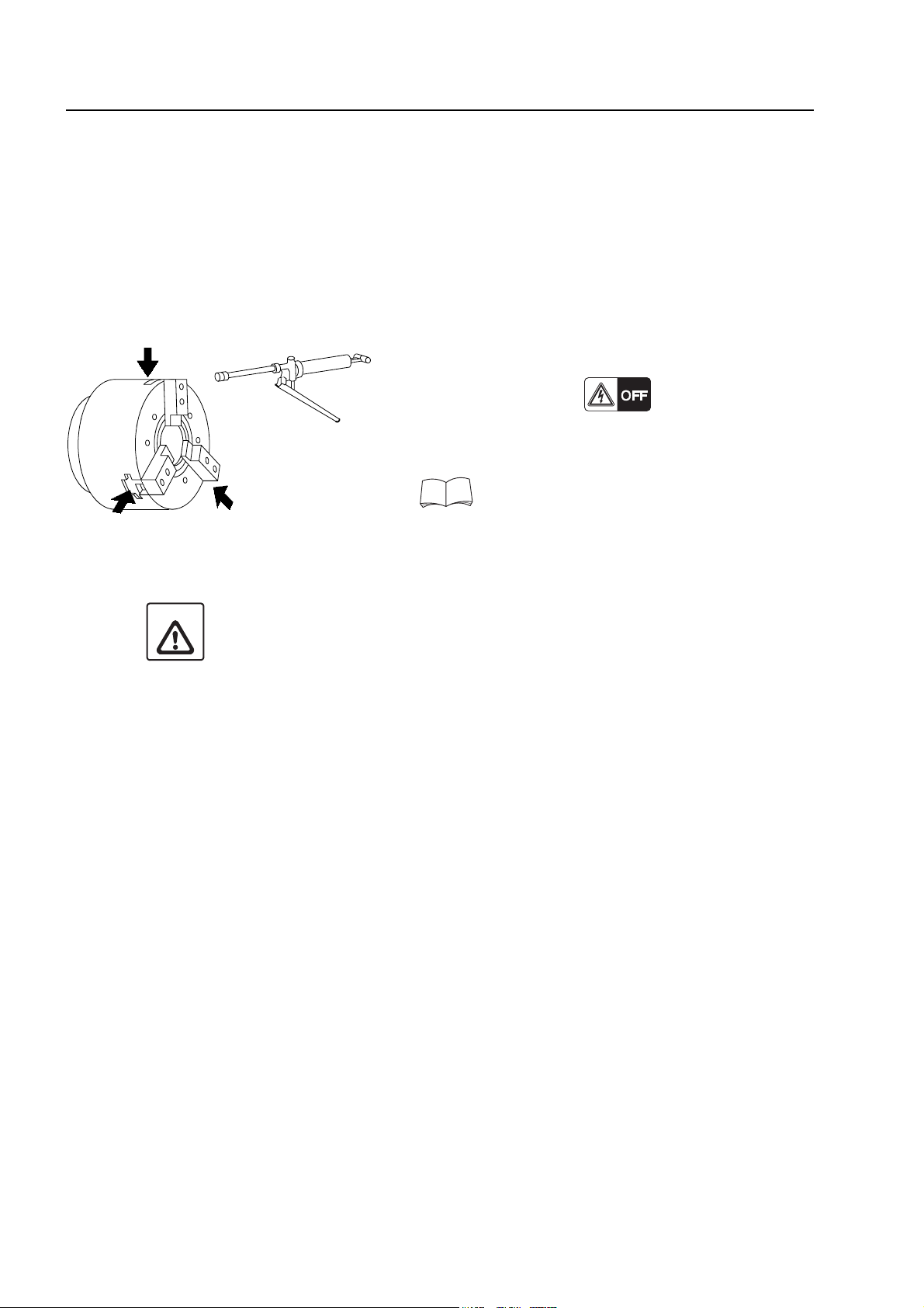
4.3 Greasing the Chuck Master Jaws
If the master jaws are not lubricated properly with grease, the gripping force of the chuck will be
reduced. If the spindle is rotated while the master jaws are not properly greased, the workpiece
will fly out of the chuck, causing injuries and machine damage.
Apply grease to the master jaws at least once a day, before starting the day's operation.
<Procedure>
1) Stop the spindle.
2) Turn off the power.
3) Supply grease from the grease cup around the
chuck.
For the name and volume of the cooling oil,
refer to the OILING CHARTS in the
MAINTENANCE INFORMATION published
separately.
CAUTION
Coolant splashed on the chuck will wash away the grease. Therefore, supply grease
as often as possible.
Page 14

5. INSPECTION OF THE CHUCK
<Daily oiling>
To maintain high chuck accuracy over a prolonged period, it is necessary to supply lubricating oil.
Improper lubrication will cause the following problems.
• Faulty operation at low hydraulic pressure
• Insufficient gripping force
• Low gripping accuracy
• Abnormal wear
• Seizure
To avoid those problems, be sure to supply lubricating oil properly.
The diagram below indicates how greasing influences chuck gripping force by showing the
relationship between the chuck gripping force and the spindle speed.
DAILY INSPECTION A-7
Example) SL-25MC, Chuck HOIMA10A6 (Howa), Cylinder HH4C-125 (Howa)
44.1
39.2
34.3
29.4
24.5
Gripping Force (kN (lbf))
19.6
14.7
0 500 1000 1500 2000 2500
Spindle Speed (min−1)
The diagram above is for reference purposes only. The actual gripping force will vary
NOTE
Greasing after
disassembling and cleaning
After greasing
Before greasing
depending on the machine model, chuck and cylinder used by the customer. In any case,
however, the chuck gripping force is reduced if the chuck is not greased properly. To
obtain the correct chuck gripping force, it is necessary to grease the chuck at least once a
day, before starting operation.
<Daily cleaning>
At the end of each day, when operation is completed, clean the chuck body and slideways.
Page 15

A-8 DAILY INSPECTION
6. CLEANING MACHINING CHAMBER/SETUP STATION
To maintain machining accuracy for the optimum length of time, always clean the machining
chamber and setup station daily following completion of machine operations.
DANGER
CAUTION
When inspecting and cleaning the machining chamber and setup station,
turn OFF the main power and disconnect the plant-side power supply
(breaker).
Do not use compressed air to clean the machining chamber and setup station.
If compressed air is used inside the machining chamber and setup station, chips and
coolant may enter the spindle tapered section and bearings resulting in serious
damage.
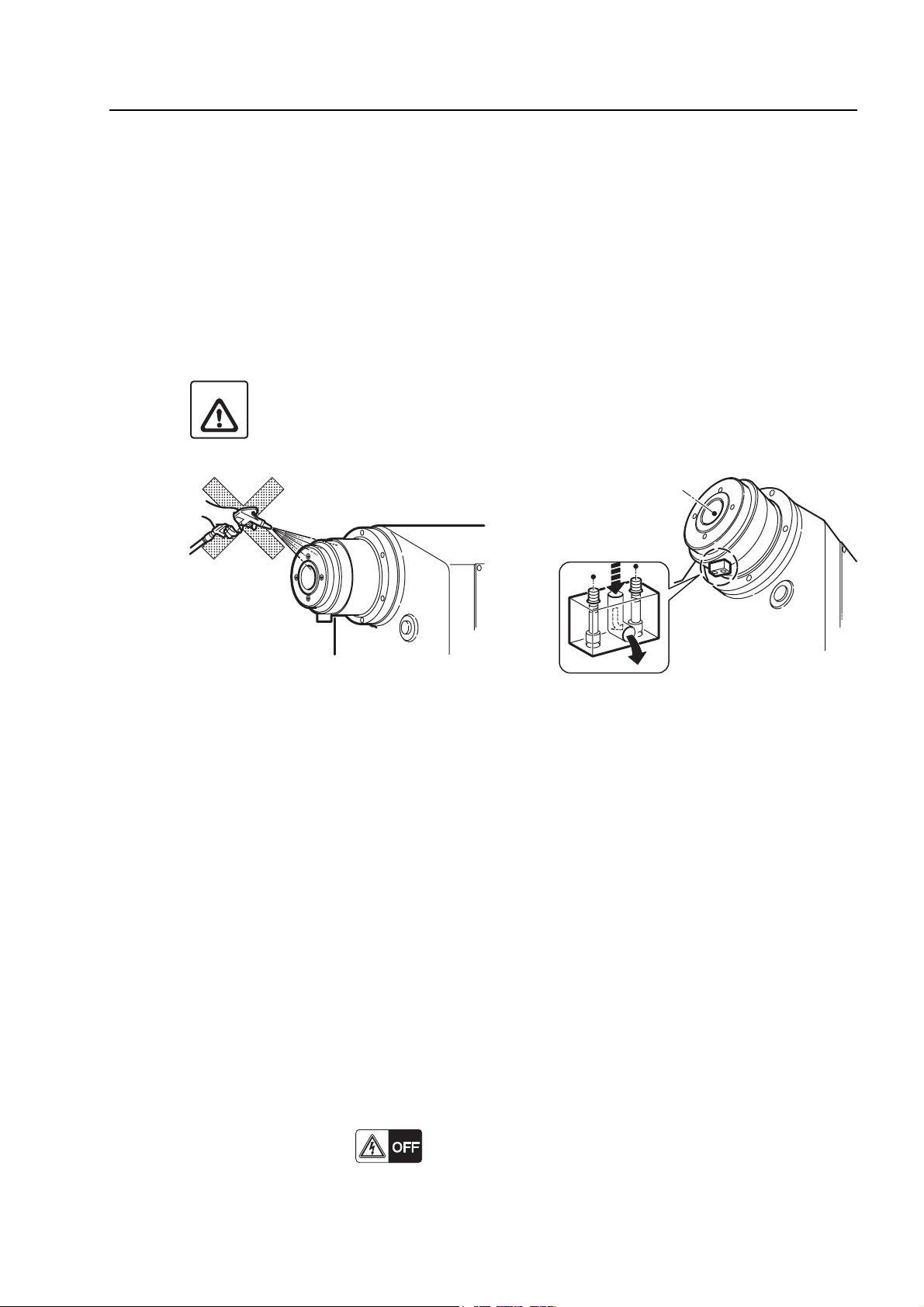
6.1 Cleaning the Front Cover of the Spindle
Dust and foreign matter will accumulate in the coolant holes on the front cover of the spindle
allowing coolant to enter the bearings. This will cause the bearings to seize.
Clean the coolant holes in the front cover of the spindle at least once a week.
<Cleaning interval>
Every 50 hours of operation
CAUTION
Do not use compressed air to remove dust and foreign matter from the coolant holes.
If compressed air is used, dust and foreign matter will enter the bearings.
Coolant discharging hole
Page 16
DAILY INSPECTION A-9
6.2 Cleaning the Front Cover of the Tailstock (with Built-in Tailstock Spindle)
Dust and foreign matter will accumulate in the coolant holes on the front cover of the tailstock
allowing coolant to enter the bearings. This will cause the bearings to seize.
Clean the coolant holes in the front cover of the tailstock at least once a week.
<Cleaning interval>
Every 50 hours of operation
CAUTION
Do not use compressed air to remove dust and foreign matter from the coolant holes.
If compressed air is used, dust and foreign matter will enter the bearings.
6.3 Cleaning the Slideway Protection Covers
During dry cutting or when machining cast workpieces, carefully remove chips from the machine
so that they do not accumulate.
Be aware that any chip accumulation on moving parts, such as the slideway protection covers, will
interfere with proper operation and lead to mechanical problems.
6.4 Cleaning the Front Door Rail
If chips accumulate on the front door rail, the door will not open/close smoothly.
Clean the front rail regularly.
<Cleaning interval>
Every 50 hours of operation
<Procedure>
1) Turn off the power.
2) Remove the chips that have accumulated on the front door rail.
Page 17

A-10 DAILY INSPECTION
6.5 Cleaning the Rear of the Cylinder (Hollow Chuck)
Coolant and chips flow to coolant pan at the rear of the cylinder via the through hole in the draw
pipe.
The coolant returns to the coolant tank via the drain hose.
Chips accumulate on the punched-metal sheet at the rear of the cylinder.
CAUTION
Remove chips from the punched-metal sheet every day. If chips are left to accumulate,
coolant will overflow and spill onto the shop floor.
Coolant will flow into the hydraulic oil tank via the cylinder drain, inhibiting proper
machine operation.
<Procedure>
1) Turn off the power.
2) Remove the cylinder cover at the left side of the machine.
3) Remove the chips that have accumulated on the punched-metal sheet at the rear of the
cylinder.
CAUTION
NOTE
Do not touch the chips bare handed.
Remove coolant and chips that have accumulated in the cylinder at regular intervals by
detaching the rear cover of the cylinder.
Page 18

DAILY INSPECTION A-11
7. CLEANING THE DRAIN OIL RECEIVER FOR THE
LUBRICATING OIL
If the drain oil receiver for the lubricating oil is at the rear or the side of the machine, dispose of the
waste oil before the drain oil receiver becomes full.
The drain oil receiver is provided to prevent lubricating oil being mixed into the coolant. It is
effective when water-soluble coolant is used to prevent deterioration of the coolant due to mixing
of lubricating oil.
(1) Because impurities are contained in the drain oil, do not reuse the oil in the lubrication
NOTE
tank. Always use fresh lubricating oil when replenishing the lubrication tank.
(2) Entrust the disposal of waste oil and coolant to a party qualified to dispose of
industrial wastes or a gas station with the appropriate facilities.
(3) The drain oil receiver is not available for some models.
These models collect the drain oil in the coolant tank.
For details on the disposal of waste oil, refer to FOREWORD in this manual.
Page 19

A-12 DAILY INSPECTION
8. CLEANING RADIATOR
If the radiator on the hydraulic tank is clogged, the oil temperature rises resulting in unit failure.
Clean the radiator at regular intervals.
<Cleaning interval>
As required
<Necessary tools>
• Air gun
Radiator
<Procedure>
1) Turn OFF the main power.
2) Remove dust adhering to the radiator with a compressed air gun.
CAUTION
Protective glasses must be worn to prevent eye damage from dust or foreign matter
(those who are wearing glasses included).
Page 20
DAILY INSPECTION A-13
9. PRECAUTIONS WHEN USING CHIP CONVEYOR
WARNING
CAUTION
(1) Do not operate the chip conveyor or perform maintenance and
inspection tasks without reading and obtaining a thorough
understanding of the contents of the chip conveyor instruction
manual "COOLANT FILTER MANUAL" published separately.
(2) Keep the chip conveyor instruction manual "COOLANT FILTER
MANUAL" on hand to enable immediate reference when operating the
chip conveyor and performing maintenance and instruction tasks.
(3) Do not place hands or feet inside the chip conveyor during operation
to prevent serious injury due to entanglement in rotating components
or by being crushed between moving parts.
(1) Do not operate the chip conveyor intermittently.
Intermittent operation causes fine chips to accumulate between the belts and/or on
the conveyor bottom plates, resulting in conveyor malfunction such as tripping of
the thermal relay.
Always operate the chip conveyor continuously.
(2) The chip conveyor cannot carry materials larger than cutting chips.
If tools and other such materials are mistakenly placed on the conveyor during
operation, the chip conveyor will be damaged.
(1) Close the operator panel-side door before operating the chip conveyor.
NOTE
(2) The chip conveyor cannot discharge all types of chips. Carefully consider appropriate
cutting conditions to generate chips which can be removed from the machining
chamber.
Page 21

A-14 DAILY INSPECTION
9.1 Cleaning Chip Conveyor
<Cleaning interval>
Once or twice daily.
<Necessary tools>
• Rags
<Procedure>
CHIP CONVEYOR
FOR STOP BACK
1) Press the CHIP CONVEYOR [FOR] button on the
operation panel.
The [FOR] button is illuminated.
The chip conveyor moves forward to discharge chips
from machine.
2) Press the CHIP CONVEYOR [STOP] button.
The [STOP] button is illuminated.
The chip conveyor stops.
3) Place an adequate quantity of rags on the conveyor
belt.
WARNING
Before placing rags on the conveyor
belt, disconnect power to prevent
entanglement of fingers and hands in
the rotating unit or between moving
parts, which may result in death or
serious injury.
4) Press the CHIP CONVEYOR [BACK] button. The
[BACK] button is illuminated.
Keep pressing the [BACK] button. The chip
conveyor moves backward to discharge chips and
rags out of the machine only when the button is
pressed.
This completes the chip conveyor cleaning procedure.
For further details on the cleaning procedure,
refer to the chip conveyor instruction manual
"COOLANT FILTER MANUAL" published
separately.
Page 22

DAILY INSPECTION A-15
10. OPENING/CLOSING THE ELECTRICAL CABINET DOOR
DANGER
Before attempting maintenance and inspection inside the electrical
cabinet, be sure to turn OFF the plant-side power supply (circuit breaker).
Even when the main power switch on the electrical cabinet is turned OFF,
parts of the cabinet may still hold residual current and give an electric
shock if accidentally touched.
Do not touch devices installed inside the electrical cabinet at heights of 2 m or greater
NOTE
above the ground as these devices do not require maintenance or inspection.
10.1 Opening the Electrical Cabinet Door
<Procedure>
1) Turn OFF the main power.
CONTROL BOX
DOOR INTERLOCK
ON OFF
CAUTION
Place the control box door interlock switch
installed in the electrical cabinet door in the
[OFF] position when opening the electrical
cabinet door with the main power ON.
2) Insert the key into the keyhole below the lever on the
electrical cabinet.
3) Turn the key to release the electrical cabinet door
lock. The lever is pushed outward when the key is
inserted.
4) Turn the lever 90° counterclockwise.
Page 23

A-16 DAILY INSPECTION
5) Open the electrical cabinet door.
10.2 Closing the Electrical Cabinet Door
1) Close the left side of the electrical cabinet door.
2) Close the right side of the electrical cabinet door.
3) Rotate the lever downward.
4) Push the lever inward.
5) Turn the key below the lever to lock the door.
6) Pull out the key.
The customer is responsible for supervising usage
NOTE
and safe storage of the key.
CONTROL BOX
DOOR INTERLOCK
ON OFF
7) Place the CONTROL BOX DOOR INTERLOCK
switch installed on the electrical cabinet door in the
[ON] position.
Page 24

10.3 Main Power Switch
DAILY INSPECTION A-17
WARNING
When electrical over-current occurs in the machine, the breaker is actuated, the power supply is
automatically turned OFF, and the main power switch automatically moves to the [TRIP] setting.
To reset, return the handle to the [OFF] setting and then turn the handle back to the [ON] setting.
<How to Lock the Main Power Switch>
Lock the main power switch using the following procedure when performing maintenance
procedures considered dangerous if the power is ON.
Type A
1) Place the main power switch in the [OFF] position.
2) Attach a padlock.
When the main power switch is locked, maintenance procedures are
performed. Do not place the main power switch in the [ON] position.
Refer to the OPERATION MANUAL published separately for details on turning the
power ON and OFF.
Type B
1) Place the main power switch in the [OFF] position.
2) Pull out the lock plate.
3) Attach a padlock.
Lock plate
Page 25

A-18 DAILY INSPECTION
Type C
1) Place the main power switch in the [OFF] position.
2) While pushing the shutter plates in the direction of arrows, attach a padlock.
Type D
Shutter plate
1) Place the main power switch in the [OFF] position.
2) Put a driver into the release screw.
When the release screw is not prepared, just pull out the lock plate.
NOTE
3) While turning the driver CCW, pull out the lock plate.
4) Attach a padlock.
Driver
Lock plate
Page 26

DAILY INSPECTION A-19
11. PREPARATION FOR MACHINE OPERATION AFTER PROLONGED IDLE PERIOD
Perform the following operations in the order specified after the machine has been idle for a
*
prolonged period of time
(1) Forced lubrication of ball screws and spindle bearings.
(2) Full stroke travel of all axes.
(3) Spindle warm-up
.
NOTE
*
Prolonged period of time: Two days or more
<Forced lubrication of ball screws and spindle bearings>
Press the manual lubrication button on the lubrication tank for more than 10 seconds. Lubricant is
supplied to the nuts on the ball screws and the spindle bearings.
Manual lubrication button
Page 27

CHAPTER B
REGULAR INSPECTION
Page 28

CONTENTS
B : REGULAR INSPECTION
1. IMPORTANCE OF INSPECTIONS . . . . . . . . . . . . . . . . . . . . . . . . . . . . . . . . . . . . . . . B-1
2. CHECKS PRIOR TO MAINTENANCE . . . . . . . . . . . . . . . . . . . . . . . . . . . . . . . . . . . . . . B-2
3. PRECAUTIONS TO BE OBSERVED BY TECHNICIANS . . . . . . . . . . . . . . . . . . . . . . . B-3
4. CLEANING THE ELECTRICAL CABINET AIR FILTER . . . . . . . . . . . . . . . . . . . . . . . . B-5
5. CLEANING THE COOLANT TANK . . . . . . . . . . . . . . . . . . . . . . . . . . . . . . . . . . . . . . . . B-6
6. CLEANING THE LUBRICATING OIL TANK . . . . . . . . . . . . . . . . . . . . . . . . . . . . . . . . . B-7
6.1 Lubricating Unit Tank/Suction Filter/Fill Port Filter Cleaning . . . . . . . . . . . . . . . . B-7
6.2 Inspection Items for the Lubricating Oil Tank . . . . . . . . . . . . . . . . . . . . . . . . . . . . B-8
6.3 When the Lubricant Pressure does not Rise . . . . . . . . . . . . . . . . . . . . . . . . . . . . B-9
6.4 Disassembling/Cleaning the Relief Valve. . . . . . . . . . . . . . . . . . . . . . . . . . . . . . B-11
6.4.1 Relief Valve Disassembly . . . . . . . . . . . . . . . . . . . . . . . . . . . . . . . . . . . B-11
6.4.2 Relief Valve Cleaning . . . . . . . . . . . . . . . . . . . . . . . . . . . . . . . . . . . . . . B-11
6.4.3 Relief Valve Adjustment . . . . . . . . . . . . . . . . . . . . . . . . . . . . . . . . . . . . B-11
7. CLEANING THE SUCTION STRAINER IN THE HYDRAULIC OIL TANK . . . . . . . . . B-12
8. CLEANING THE FANS . . . . . . . . . . . . . . . . . . . . . . . . . . . . . . . . . . . . . . . . . . . . . . . . B-14
9. CLEANING INSIDE THE ELECTRICAL CABINET . . . . . . . . . . . . . . . . . . . . . . . . . . . B-15
10. REPLACING THE MACHINING CHAMBER OBSERVATION WINDOW . . . . . . . . . . . B-16
11. INSPECTION AND REPLACEMENT OF SLIDE SEALS . . . . . . . . . . . . . . . . . . . . . . B-18
12. TIMING BELT REPLACEMENT . . . . . . . . . . . . . . . . . . . . . . . . . . . . . . . . . . . . . . . . . B-19
13. CHANGING FLUID OF HYDRAULIC TANK . . . . . . . . . . . . . . . . . . . . . . . . . . . . . . . . B-20
14. CHANGING THE BATTERY. . . . . . . . . . . . . . . . . . . . . . . . . . . . . . . . . . . . . . . . . . . . . B-22
14.1 Replacing CNC Memory Back-up Batteries . . . . . . . . . . . . . . . . . . . . . . . . . . . . B-24
14.1.1 Type 1 . . . . . . . . . . . . . . . . . . . . . . . . . . . . . . . . . . . . . . . . . . . . . . . . . . B-24
14.1.2 Type 2 (Electrical Cabinet Side) . . . . . . . . . . . . . . . . . . . . . . . . . . . . . . B-25
14.1.3 Type 2 (Operation Panel Side) . . . . . . . . . . . . . . . . . . . . . . . . . . . . . . . B-26
14.1.4 Type 3 (2CR5 Type Lithium Photo Battery) . . . . . . . . . . . . . . . . . . . . . B-28
14.1.5 Type 4 . . . . . . . . . . . . . . . . . . . . . . . . . . . . . . . . . . . . . . . . . . . . . . . . . . B-29
Page 29

14.2 Replacing the Servo Absolute Position Sensing Battery . . . . . . . . . . . . . . . . . . B-30
14.2.1 Type 1 (Alkaline Battery/Manganese Battery). . . . . . . . . . . . . . . . . . . . B-30
14.2.2 Type 1 (Lithium Battery) . . . . . . . . . . . . . . . . . . . . . . . . . . . . . . . . . . . . B-31
14.2.3 Type 2 . . . . . . . . . . . . . . . . . . . . . . . . . . . . . . . . . . . . . . . . . . . . . . . . . . B-33
14.2.4 Type 3 (2CR5 Type Lithium Photo Battery). . . . . . . . . . . . . . . . . . . . . . B-35
14.2.5 Type 4 . . . . . . . . . . . . . . . . . . . . . . . . . . . . . . . . . . . . . . . . . . . . . . . . . . B-36
15. ADJUSTING THE SETTING PRESSURE . . . . . . . . . . . . . . . . . . . . . . . . . . . . . . . . . B-38
15.1 Adjusting Hydraulic Unit Main Pressure . . . . . . . . . . . . . . . . . . . . . . . . . . . . . . . B-38
15.2 Adjusting Air Pressure . . . . . . . . . . . . . . . . . . . . . . . . . . . . . . . . . . . . . . . . . . . . B-39
16. ADJUSTING THE OIL SKIMMER SEPARATION TANK DRAIN (OPTION) . . . . . . . . . B-40
Page 30

REGULAR INSPECTION B-1
1. IMPORTANCE OF INSPECTIONS
Daily lubrication and inspection by operators and regular inspection by maintenance engineers
are the keys to long-lasting machine accuracy.
Prior to inspection, confirm the following points:
(1) Any abnormality discovered during daily inspections must be reported to maintenance
engineers. If necessary, repair or replacement is to be performed immediately.
(2) Maintenance engineers must take immediate and proper action in compliance with the
instructions of operators who are in charge of daily inspection.
(3) For queries or concerns related to the contents of the instruction manuals, circuit diagrams,
and ladder diagrams, contact Mori Seiki Service Department for assistance.
(4) If the cause of a problem cannot be determined or remedied, contact Mori Seiki Service
Department and/or parts manufacturers for assistance.
<Maintenance/inspection sequence>
Daily oil replenishment and inspection by machine operator
Maintenance and repairs by maintenance engineers
Service request call to Mori Seiki and/or parts manufacturer
For details on checks to be performed, refer to "REGULAR INSPECTION LIST" published
NOTE
separately.
Page 31

B-2 REGULAR INSPECTION
2. CHECKS PRIOR TO MAINTENANCE
DANGER
WARNING
(1) Never close the operator door when working inside the machine with
the main power switch ON. When closed, the operator door is
automatically locked and the power supply to servomotors
connected. Rapid machine operations may start unexpectedly.
(2) When working inside the machine with the main power switch ON,
carry the door lock prevention key at all times. Removing the key
prevents the door from closing by mistake.
(3) Ensure that the main power is turned OFF and locked when
connecting the power.
(4) Provide clear warning that the machine is being maintained and
operations cannot be performed.
(1) Ensure only parts specified by Mori Seiki are used during parts
replacement. Mori Seiki does not accept responsibility for problems
arising from the use of non-specified parts. Use of non-specified
parts not only impairs machine performance but also leads to unsafe
operating conditions that may result in serious injury or machine
damage.
(2) Wear clothing appropriate to the type of maintenance operation to be
performed.
Approaching the machine with loose clothing may lead to serious
injury due to entanglement in rotating parts or by being crushed by
moving parts.
CAUTION
(3) When two or more persons are working on the machine
simultaneously, awareness of procedures being performed and clear
communication between personnel must be maintained at all times.
Operating the machine or a crane in the surrounding area without
adequate checks to determine if other personnel are working inside or
around the machine may result in serious injury.
(1) Listen to operators in charge of machine operation to understand the problem
accurately.
(2) Study the actual conditions of machine and plan the scope of repair procedures.
(3) Study the specifications, construction, and functions of the part of the machine to
be repaired.
(4) If two or more maintenance technicians or personnel from other sections must
work on the machine, discuss the repair procedure with all personnel in advance
so that everyone can understand the problem accurately.
(5) Prepare spare parts and consumables to be used in advance.
Page 32

REGULAR INSPECTION B-3
3. PRECAUTIONS TO BE OBSERVED BY TECHNICIANS
DANGER
(1) Electrical wiring work must be entrusted to a licensed electrical
technician. If a person without knowledge of electrical safety
practices attempts this work, he or she could be electrocuted.
(2) Always lock out the power to the machine before carrying out
inspections, repairs, or maintenance work. In addition, set the main
switch to the OFF position and lock it, and place "UNDER
MAINTENANCE" signs around the machine to stop anyone from
switching on the power or operating the machine while the work is in
progress. If inspection or maintenance work is carried out with the
power switched on, machine elements could be moved, and the
inspection or maintenance personnel could be seriously injured by
being entangled in the rotating parts or crushed by the moving parts
of the machine.
For details on locking the main power switch, refer to 10.3 "Main
Power Switch".
(3) Never touch a switch, button, or key with wet hands.
If it is not properly grounded or is leaking current, you could receive
an electric shock.
WARNING
(1) Machine operators and authorized personnel working inside the plant
and in the vicinity of the machine must put their clothing and hair in
order so that there is no danger they will be entangled in the machine.
If you have uncontrolled long hair or loose clothing and it gets caught
in the machine, you will be seriously injured by being entangled in the
rotating parts of the machine or crushed by its moving parts. Always
wear safety shoes, eye protectors and a helmet.
(2) The parameters are set on shipment in accordance with the machine
specifications; do not change them without first consulting Mori Seiki.
If the parameters are changed without consultation, the machine may
operate in an unexpected manner, causing accidents involving
serious injuries or damage to the machine.
(3) The machine specifications are set before shipping so that the
machine can deliver its full performance. Changing the settings
without consultation may lead to accidents involving serious injuries,
impaired machine performance, and considerable shortening of the
machine service life. If the specifications and/or settings have to be
changed or the machine has to be modified to meet new machining
requirements or due to changes in the operating conditions, consult
Mori Seiki.
Page 33

B-4 REGULAR INSPECTION
WARNING
CAUTION
(4) When two or more people are involved in maintenance work, they
must cooperate carefully, communicating as fully as possible.
If one worker moves the machine without noticing that there is
another worker inside or near the machine, he could seriously injure
that worker or damage the machine.
(5) When changing parts, be sure to use genuine parts specified by Mori
Seiki. Mori Seiki cannot accept responsibility for any trouble arising
from the use of parts not specified by Mori Seiki. Using parts that are
not specified will not only impair the performance of the machine; it
will also make the machine unsafe and could lead to serious injuries
or damage to the machine.
(6) When using equipment such as wires, ropes, and cranes, make sure
that they can bear the mass to be hoisted. If they cannot bear the load
it will fall and could cause serious injuries or damage the machine.
(1) Use service tools appropriate for the intended work. If the tools are not
appropriate, parts could be broken or bolts not tightened properly, leading to
machine failure.
(2) Do not place service tools or parts directly on the slideways. This could cause
scratches or other damage to the slideways, adversely affecting machine life.
(3) Do not climb on top of the machine. If you lose your balance, you could fall off and
injure yourself. Use a ladder or service platform when you have to work in high
places.
(4) When moving a heavy object, always carry it with the help of at least one other
person or use a crane. If you attempt to carry a heavy object by yourself, you
could be injured.
Page 34

REGULAR INSPECTION B-5
4. CLEANING THE ELECTRICAL CABINET AIR FILTER
The electrical cabinet is not cooled directly by outside air; it is cooled indirectly through heat
exchange between outside air, taken into the cabinet through the duct, and inside air.
Therefore, if the air filter at the air suction port is clogged, the inside of the electrical cabinet will
not be cooled satisfactorily.
<Cleaning interval>
Every 50 hours of operation
<Procedure>
1) Turn off the power.
2) Remove the filter cover from the electrical cabinet.
Air filter
Filter cover
3) Clean the filter using neutral detergent.
4) Dry the filter.
5) Mount the filter cover in the electrical cabinet.
6) Turn on the power.
The shape of the electrical cabinet air filter may
NOTE
differ depending on the machine model.
Page 35

B-6 REGULAR INSPECTION
5. CLEANING THE COOLANT TANK
If fine chips and other foreign matter accumulate in the coolant tank, the specified coolant supply
cannot be maintained and coolant supply to the cutting point is insufficient.
In addition, if contaminated coolant is pumped from the coolant tank, the service life of the pump is
reduced.
Clean coolant tank periodically.
<Cleaning interval>
Every 500 hours of operation
(1) When machining cast iron or similar material that generates fine chips, clean coolant
NOTE
tank more frequently.
(2) A certain amount of lubricant also runs into the coolant tank. Even if no coolant is
used in machining, clean the coolant tank at regular intervals.
(3) The cleaning interval may differ depending on the machine model. Refer to the
REGULAR INSPECTION LIST in the MAINTENANCE INFORMATION published
separately.
<Procedure>
1) Press the coolant switch (off) to stop coolant supply.
2) Turn off the power.
3) Loosen the connector and remove coolant motor pipe and wiring.
4) Remove the drain plug and discharge the coolant of the coolant tank.
5) Pull out the coolant tank.
Some models have the coolant tank integrated with the bed, making it impossible to
NOTE
remove the coolant tank.
6) Clean the inside of the coolant tank and the coolant filter.
7) Wind seal tape onto the drain plug and fit it to the coolant tank.
8) Mount the coolant tank to the machine.
CAUTION
When installing the machine, mount the coolant tank and the chip bucket by pushing
them into an appropriate position. Otherwise, coolant may be splashed around the
machine causing the operator or persons around the machine to fall and injure
themselves.
9) Connect the coolant motor pipe and wiring.
10) Supply coolant in the tank.
For the capacity of the coolant tank, refer to the OILING CHARTS in the
MAINTENANCE INFORMATION published separately.
Page 36

REGULAR INSPECTION B-7
6. CLEANING THE LUBRICATING OIL TANK
6.1 Lubricating Unit Tank/Suction Filter/Fill Port Filter Cleaning
<Cleaning interval>
Tank: Every 1000 hours of operation.
Suction filter/fill port filter: Every 500 hours of operation.
<Necessary tools>
• Screwdriver
• Neutral detergent/kerosene (for cleaning)
<Procedure>
Terminal box
Manual
lubrication
button
Two screws
Four screws
Fill port filter
1) Turn OFF the main power.
2) Remove the tank as described below:
a) Loosen the two screws using a phillips head
screwdriver and open the terminal box.
b) Loosen the four screws on the bottom of the
terminal box.
c) Remove the tank.
Take care not to spill lubricant when removing the
NOTE
tank.
3) Clean the inside of the lubricating unit tank using a
neutral detergent.
4) Remove the suction filter from the suction port.
5) Clean the suction filter with kerosene.
Blow compressed air to dry.
6) Reinstall the suction filter in the suction port.
7) Loosen the two screws to remove the fill port filter.
8) Clean the fill port filter.
9) Reinstall the fill port filter.
Suction filter
Tank
Oil level gage
10) Remount the tank.
11) Using an oil can, add lubricant to the maximum level
in the lubricating unit tank while checking the oil level
gage.
12) Turn ON the main power.
Page 37

B-8 REGULAR INSPECTION
13) Press the manual lubrication button for more than 10
seconds to supply lubricant to the slideways.
14) Make sure that lubricating oil is supplied to the
slideway surfaces.
6.2 Inspection Items for the Lubricating Oil Tank
Periodic inspection items for the lubricating oil tank are indicated below.
By referring to the inspection items, carry out inspection and maintenance work at the specified
inspection intervals.
WARNING
No. Inspection Item Contents
1 Fill port filter
2 Oil in the tank Check for deterioration, oxidation, and dirt.
3 Inside of the tank Check for chips, foreign matter and sludge.
4
5 Piping tube Check the piping tube for damage.
6
(7) Always turn the power OFF before performing inspection and
cleaning the lubricating oil tank. When the power is turned ON, the
internal fan starts to rotate. If the fan is rotating during the cleaning
procedure, hands or clothing may become entangled, resulting in
serious injury.
(8) Use only kerosene for cleaning the lubricating oil tank and the fill port
filter. Do not use volatile fluid such as gasoline or thinner.
Check that the fill port filter is properly installed, that the filter is
not damaged and that foreign matter does not adhere to the filter.
Tightness of piping
connections
Oil consumption in
the tank
Check for oil leakage from all joints.
Check that oil consumption in the tank is appropriate.
7Pump
8 Distributor Check that oil is supplied from the distributor properly.
Turn on the lubricating oil pump and check that the lubricant
pressure rises to the setting pressure properly.
Page 38

6.3 When the Lubricant Pressure does not Rise
When the lubricant pressure does not rise, the lubricating oil pump may be malfunctioning, or
lubricant leakage is occurring. Disconnect the piping according to the following procedure to
locate the cause and solve the problem.
<Procedure>
1) Remove the line filter piping from the lubricating oil pump.
2) Place a plug over the line filter discharge outlet.
3) Press the manual lubrication button for more than 10 seconds. Check that the lubricant
pressure rises to between 1.0 MPa - 1.2 MPa during pump operation.
<Cause>
This problem may be caused by the following two factors.
• When the lubricant pressure does not rise: The lubricating unit may be malfunctioning.
REGULAR INSPECTION B-9
• When the lubricant pressure rises: The piping or the distributor may be
malfunctioning.
Refer to the following table to solve the problem.
<Troubleshooting>
Condition Cause Action
Suction filter clogging Cleaning or replacement
When the lubricant
pressure does not rise
(lubricating unit
malfunction)
Relief valve clogging or damage
Pump malfunction
Disassembly/cleaning or
replacement
Air bleeding
Replacement
Piping damage Replacement
When the lubricant
pressure rises (piping or
distributor malfunction)
NOTE
*1
Following air bleeding from the piping, ensure that the pressure rises to between
Failure in air bleeding from the
piping
Distributor malfunction
Air bleeding from the piping
Replacement
1.0 MPa - 1.2 MPa.
*1
*2
*1
*2
*2
Contact Mori Seiki Service Department for assistance.
Page 39

B-10 REGULAR INSPECTION
Manual lubrication button
Relief valve
Line filter piping
Line filter discharge outlet
(plug insertion point)
Suction filter
Page 40

6.4 Disassembling/Cleaning the Relief Valve
If the lubricating unit abnormal pressure is caused by a relief valve malfunction, disassemble and
clean the relief valve.
6.4.1 Relief Valve Disassembly
Remove the adjusting screw to disassemble the relief valve as indicated below.
REGULAR INSPECTION B-11
Adjusting screw
6.4.2 Relief Valve Cleaning
Clean the disassembled relief valve with compressed air and kerosene.
• Take care to check for dust contamination of the tapered section. If scratches are visible on
the tapered section of the relief valve, replacement is necessary.
• Cover the tapered threaded section with seal or sealing tape.
Following disassembly and cleaning of the relief valve, press the manual lubrication button
NOTE
to bleed air from the piping.
Lock nut
Valve
Tapered threaded section
Relief valve disassembly
6.4.3 Relief Valve Adjustment
Following disassembly and cleaning, adjustment of the relief valve is required. Bleed air from the
piping properly prior to adjustment.
• Press the manual lubrication button.
• Set the pump discharge pressure to 1.2 MPa using the relief valve adjusting screw.
If unable to set the pressure to 1.2 MPa, the pump is malfunctioning. Contact Mori Seiki
NOTE
Service Department for assistance.
Page 41

B-12 REGULAR INSPECTION
7. CLEANING THE SUCTION STRAINER IN THE HYDRAULIC OIL
TANK
If the suction strainer becomes clogged, pumps and piping may be damaged, resulting in
hydraulic unit failure. Clean the suction strainer at regular intervals.
<Cleaning interval>
Every 1000 hours of operation.
<Necessary tools>
• Spanner, monkey wrench
• Kerosene (for cleaning)
• Compressed air gun
<Procedure>
1) Turn OFF the main power.
2) Drain oil in the tank.
Refer to steps 3) - 6) in 13. "CHANGING FLUID OF HYDRAULIC TANK".
3) Loosen the hose band.
4) Disconnect the piping.
5) Remove the tank upper plate.
Hose band
Page 42

6) Clean the suction strainer using the following procedure:
a) Remove the suction strainer.
REGULAR INSPECTION B-13
CAUTION
Clamp the suction pipe with a pipe wrench and turn the suction strainer to the left with a
monkey wrench. If the suction strainer is turned without clamping the suction pipe, the
suction pipe will turn with it, causing an oil leak.
b) Clean the suction strainer with kerosene.
c) Dry the suction strainer using compressed air.
CAUTION
Protective glasses must be worn to prevent eye damage form dust or foreign matter
(those who are wearing glasses included).
d) Apply sealing tape to the threaded section of the suction pipe and reattach the suction
strainer.
7) Clean the inside of the tank with kerosene.
8) Remove foreign matter form around the drain plug using a brush.
× 4
× 8
Suction pipe
Monkey wrench
Suction strainer
9) Remount the tank upper plate.
10) Remount the hydraulic unit on the machine.
11) Connect the piping.
12) Remove the fill port cap.
13) Supply oil while checking the oil level gage.
14) Turn ON the main power.
15) Confirm pump pressure and suction noise are normal.
If the suction sound is louder than prior to oil replacement, check the oil level again.
NOTE
Page 43

B-14 REGULAR INSPECTION
8. CLEANING THE FANS
<Battery position>
• Electrical cabinet
• Machine side cover
• Hydraulic pump
<Cleaning interval>
Every 1000 hours of operation
<Procedure>
1) Turn off the power.
2) Remove the fan cover.
3) Blow the fan with compressed air.
The temperature inside the cabinet must be lower than 45°C; measure the temperature
periodically.
If it is higher than 45°C, check the ambient temperature, cooling fan, etc. Eliminate the cause of
the high temperature.
Page 44

REGULAR INSPECTION B-15
9. CLEANING INSIDE THE ELECTRICAL CABINET
Although the electrical cabinet is constructed to shut off external air, foreign matter such as dust
and dirt may enter the cabinet through the gap or when the door is opened.
Accumulation of foreign matter on the printed circuit boards or other electronic components could
cause machine malfunction.
Clean the inside of the electrical cabinet at regular intervals.
<Cleaning interval>
Every 1000 hours of operation
<Procedure>
1) Turn off the power.
2) Open the electrical cabinet door.
3) Remove dust inside the electrical cabinet with a
vacuum cleaner.
CAUTION
4) Close the electrical cabinet door.
Never touch printed circuit boards or parts
around the connector.
Also avoid subjecting them to shock.
Otherwise, the machine may be damaged.
Page 45

B-16 REGULAR INSPECTION
10. REPLACING THE MACHINING CHAMBER OBSERVATION WINDOW
The machining chamber observation window consists of polycarbonate and tempered glass.
Polycarbonate effectively resists strong impact. Tempered glass prevents the window becoming
opaque due to repeated cutting chip impacts. The machining chamber observation window is a
consumable part. Replace the window at regular intervals, or when it becomes necessary, by
following the instructions below.
WARNING
1. Window safety is guaranteed for a maximum of 2 years due to
strength reduction and must therefore be replaced at specified
intervals (once every 5 years). Replace the window immediately if it
becomes cracked or when the operator's field of view is restricted.
2. Replace the window immediately in case a strong impact was made
to the window even though the window may appear unaffected.
Once a window has been subjected to a strong impact, the strength of the
window will decrease remarkably.
3. Due to the hardness of the window, high-speed chip impacts can
cause cracks. Small initial fractures may allow the entry of coolant
which will degrade the polycarbonate and substantially weaken the
window.
4. Even small initial cracks caused by impact may spread across the
window due to the nature of the tempered glass.This is not a fault.
5. To carry out maintenance or inspection work inside the machine,
make the door lock device invalid by turning the door lock
prevention key; remove the key and bring it with you when you enter
the machine. To prevent the door being locked by mistake, lock a
padlock in the hole at the end of the door lock hasp. If the door is
closed by mistake while the door lock device is valid, the door is locked
and you may be cooped up in the machine. If the machine is started while
you are inside the machine, you will be entangled with the rotating part or
crushed between sliding parts to be seriously injured.
<Replacement Interval>
5 years
<Necessary Tools>
• Impact resistant viewing window
• Oil- and heat-resistant silicon
• wrench
Page 46

REGULAR INSPECTION B-17
(1) When replacing the machining chamber observation window, contact Mori Seiki
NOTE
Service Department and use a window of the specified type. Mori Seiki does not
accept responsibility for problems arising from the use of a non-specified window
type.
(2) The machining chamber observation window is a consumable part and is not covered
by the warranty.
(3) Check the mounting direction of the window with the sticker affixed to the window that
indicates the outer side of the window pane.
<Procedure>
1) To secure the space where you can work safely, remove tools from the spindle and
workpieces and fixtures from the table.
2) Turn OFF the main power.
3) Step inside the machining chamber and remove bolts from the rear plate securing the window
on the backside of the door.
(1) Take care not to slip and fall in the machining chamber.
NOTE
(2) Hold the window securely being careful not to drop the window.
4) Remove the old window.
In case the window pane is damaged, take sufficient care not to be injured by touching the
NOTE
damaged part of the pane.
5) Remove silicon from the window frame of the door.
6) Install a new window according to the following procedure:
a) Check the mounting direction (inner or outer side) of the window with the sticker affixed to
the window. Apply silicon around the window frame on the outer side.
b) Install the window.
c) Fix the window by tightening bolts on the rear plate.
7) Set the replacement date on the periodical inspection 1 screen.
This screen may not displayed depending on the machine model.
NOTE
Operation Manual (FUNCTION SELECTION KEYS AND DISPLAYS SCREENS:
Regular Interval Maintenance Screen)
This completes the machining chamber observation window replacement procedure.
Page 47

B-18 REGULAR INSPECTION
11. INSPECTION AND REPLACEMENT OF SLIDE SEALS
Slide seals are used on each slideway. The slide seals are used to prevent the entry of chips
beyond them and to maintain an oil film of uniform thickness.
Check the slide seals periodically.
Pay careful attention to abnormal wear on the lip or scratches or damage due to chips.
If you find any abnormality on a slide seal, replace it immediately.
WARNING
CAUTION
<Cleaning interval>
Every 1000 hours of operation
Be sure to shut off the power before inspecting or replacing the slide seal.
Before changing the slide seals, clean the inside of the machine and remove foreign
matter and chips completely. Chips or foreign matter sticking to the slideway faces will
cause machine faults.
Page 48

12. TIMING BELT REPLACEMENT
Some gravity axes are driven by a timing belt turned by a motor shaft. If the machine employs a
timing belt to drive the gravity axis, replace the timing belt periodically.
REGULAR INSPECTION B-19
WARNING
If the same timing belt is used without replacement, the axis could drop
due to damage and wear of the belt, causing damage to the machine.
Contact the Mori Seiki Service Department for assistance when replacing timing belts.
NOTE
<Replacement Interval>
Once every 5 years
CAUTION
Stop machine operation immediately and contact the Mori Seiki Service Department for
assistance in the event of any abnormality, even if replacement is not due yet.
Page 49

B-20 REGULAR INSPECTION
13. CHANGING FLUID OF HYDRAULIC TANK
Change the hydraulic fluid in the hydraulic unit tank at regular intervals while paying attention to
the following considerations.
CAUTION
(1) Maintain the oil level of hydraulic fluid in the tank at the correct level; make sure
that the pump unit does not suck in air.
(2) Keep the hydraulic fluid clean.
(3) Clean the strainer periodically to avoid clogging which will lower the pump flow
rate.
<Changing interval>
Every 1000 hours of operation
<Procedure>
1) Turn OFF the main power.
2) Remove the fill port cap.
3) Place a drain pan beneath the drain plug.
4) Remove the drain plug and drain oil in the tank.
Place a drain pan beneath the drain plug on the oil pan and remove both drain plugs on
NOTE
the hydraulic unit and oil pan.
5) Wrap sealing tape around the threaded section of the plug.
6) Replace the drain plug.
7) Supply oil while checking the oil level gage.
Fill port cap
Oil level gage
Drain pan
Drain plug
Sealing tape
Page 50

8) Replace the fill port cap.
Turn ON the main power.
9)
10) Confirm pump pressure and suction noise are normal.
If the suction noise is louder than prior to oil replacement, check the oil level again.
NOTE
REGULAR INSPECTION B-21
Page 51

B-22 REGULAR INSPECTION
14. CHANGING THE BATTERY
The machine or gantry-type loader has two types of batteries: for memory backup and for
absolute position sensing. If the battery voltage is low, the battery alarm message is displayed on
the screen. If this alarm indication is given, change the batteries by following the procedure
indicated below.
For MSC-801, refer to the MAINTENANCE INFORMATION published separately.
<Battery to be used>
Type NC Unit Memory Back-up Battery
MSC-515
MSD-515
MSC-500
MSC-501
MSD-501
MSD-501II
MSG-500
MSG-501
MSC-516
MSD-516
MSD-516II
Alkaline battery/Manganese
Type 1
MSC-518
MSD-518
battery × 2 pcs.
(Size R20, products on the
market)
MSD-518II
MSC-521
Absolute Position Sensing
Battery
Alkaline battery/Manganese
battery × 4 pcs.
(Size R20, products on the
market)
*2
Lithium battery
E67028 [A06B-6073-K001]
*2
SEICOS Σ21L
MSX-501
MSX-501III
MSX-502
MSX-502III
MSX-500
MSX-500III
MSX-511
MSX-511III
Page 52

REGULAR INSPECTION B-23
Type NC Unit Memory Back-up Battery
• Electrical cabinet side
Battery unit × 1 set
E30027
MSC-803
*1
[ER6 BKO-NC2157H01]
• Operation panel side
Type 2
Battery unit × 1 set
E03031 [ER3V]
Type 3
Type 4
MSG-803
MSX-803
MSX-803III
MSC-803
MSG-805
MSX-805
MSX-805III
MSC-700
MSC-701
*1
*1
*1
Battery unit × 1 set
E30027
[ER6 BKO-NC2157H01]
Regular lithium photo battery
× 2 pcs.
*2
2CR5 (6 V 1300 mAh)
*1
Lithium battery
E30001 [A02B-0200-K102]
Absolute Position Sensing
Battery
Battery unit × 1 set
E30028 [ER6-B4D-01]
Regular lithium photo battery
× 2 pcs.
*2
2CR5 (6 V 1300 mAh)
Lithium battery
E30234 [A06B-6114-K504]
NOTE
(1) The type of the battery used in the NC depends on the machine model.
(2) [ ]: Part number of the NC unit manufacturer
*1
(3)
Type and number of batteries may vary depending on machines models. See
the actual machine for details.
*2
The number of batteries to be used varies depending on the machine model.
Check the number by looking at the number of battery cases.
Page 53

B-24 REGULAR INSPECTION
14.1 Replacing CNC Memory Back-up Batteries
Change the Memory Back-up Battery by following the procedure indicated below.
The type and mounting position of the Memory Back-up Battery vary depending on the
NOTE
model of NC unit.
14.1.1 Type 1
CAUTION
Change batteries while power is being supplied to the NC. If batteries are changed
with the NC power supply shut off, the data stored in the memory will be lost.
To avoid the danger of lost data, you is recommended to save the memory data to an
external I/O device or a memory card.
Mori Seiki can accept no responsibility if data in the memory such as parameters and
programs is lost.
<Battery position>
The batteries are installed in the electrical cabinet door or the rear cover of the operation panel.
<Changing interval>
Once a year
When the battery alarm message is displayed on the screen.
<Procedure>
1) Turn on the power.
2) Press the NC power switch (on).
3) Rotate the mounting screws in the CCW direction
+
−
with a flat screwdriver to remove the cover.
When the cover is removed, 2 alkaline cells (D) are
visible as shown in the figure on the left.
4) Change the batteries.
Always make sure the polarity of the batteries is
NOTE
correct. The polarity varies depending on the
machine type.
5) Mount the cover.
Page 54

14.1.2 Type 2 (Electrical Cabinet Side)
REGULAR INSPECTION B-25
CAUTION
Change the battery with the power supply shut off.
Be sure to change the battery in less than 30 minutes.
The data stored in the memory will be lost if the power supply is shut off for 30 minutes
or more.
To avoid the danger of lost data, you are recommended to save the memory data to an
external I/O device.
Mori Seiki does not have any responsibility for the loss of memory data.
<Battery position>
The batteries are installed in the electrical cabinet door.
<Changing interval>
Every 5 years
When the battery alarm message is displayed on the screen.
<Procedure>
1) Press the NC power switch (off).
2) Turn off the power.
3) Remove the screws of the battery unit.
4) Pull out the battery unit.
Page 55

B-26 REGULAR INSPECTION
5) Remove the screws of the battery holder.
6) Remove the connector attached to the battery.
Do not pull the battery cable.
NOTE
7) Pull the battery out.
8) Fit a new battery.
14.1.3 Type 2 (Operation Panel Side)
CAUTION
Change the battery with the power supply shut off.
Be sure to change the battery in less than 30 minutes.
The data stored in the memory will be lost if the power supply is shut off for 30 minutes
or more.
To avoid the danger of lost data, you are recommended to save the memory data to an
external I/O device.
Mori Seiki does not have any responsibility for the loss of memory data.
<Battery position>
The battery unit is installed inside the operation panel.
Holder
Screw A
Operation panel
<Changing interval>
Every 10 years
When a battery symbol is displayed on the screen.
Page 56

<Procedure>
1) Turn on the power.
2) Press the NC power switch (on).
3) Press the NC power switch (off).
4) Turn off the power.
5) Open the operation panel door.
6) Remove the connector attached to the battery.
Do not pull the battery cable.
NOTE
7) Hold the battery by hand and loosen screw A.
REGULAR INSPECTION B-27
8) Remove the battery by pulling it sideways.
9) Place a new battery in the holder.
10) Hold the battery by hand and tighten screw A.
Page 57

B-28 REGULAR INSPECTION
14.1.4 Type 3 (2CR5 Type Lithium Photo Battery)
CAUTION
Change batteries while power is being supplied to the NC. If batteries are changed
with the NC power supply shut off, the data stored in the memory will be lost.
To avoid the danger of lost data, you is recommended to save the memory data to an
external I/O device or a memory card.
Mori Seiki can accept no responsibility if data in the memory such as parameters and
programs is lost.
<Battery position>
The batteries are installed in the electrical cabinet door.
<Changing interval>
Once a year
When the battery alarm message is displayed on the screen.
<Procedure>
1) Turn on the power.
2) Press the NC power switch (on).
3) Rotate the mounting screws in the CCW direction
with a driver to remove the cover.
When the cover is removed, 2CR5 type lithium photo
batteries are exposed.
4) Change the batteries.
Always make sure the polarity of the batteries is
NOTE
correct.
5) Mount the cover.
Page 58

14.1.5 Type 4
REGULAR INSPECTION B-29
CAUTION
Change batteries while power is being supplied to the NC. If batteries are changed
with the NC power supply shut off, the data stored in the memory will be lost.
To avoid the danger of lost data, you is recommended to save the memory data to an
external I/O device or a memory card.
Mori Seiki can accept no responsibility if data in the memory such as parameters and
programs is lost.
<Battery position>
The batteries are installed in the electrical cabinet door.
<Changing interval>
Once a year
When the battery alarm message is displayed on the screen.
<Procedure>
1) Turn on the power.
2) Press the NC power switch (on).
3) Remove the battery from the back of the power supply unit.
Hold the battery at the top and bottom faces and pull it toward you.
4) Disconnect the battery connector.
Do not pull the battery cable.
NOTE
5) Change the battery and connect the battery connector.
6) Mount the battery case.
Page 59

B-30 REGULAR INSPECTION
14.2 Replacing the Servo Absolute Position Sensing Battery
Change the Absolute Position Sensing Batteries by following the procedure indicated below.
The type and mounting position of the Absolute Position Sensing Batteries vary depending
NOTE
on the machine.
14.2.1 Type 1 (Alkaline Battery/Manganese Battery)
CAUTION
Change the batteries while power is being supplied to the NC. If the batteries are
changed with the NC power supply turned OFF, the absolute position data in the
memory will be lost.
<Battery position>
Battery box installed in the electrical cabinet door
<Changing interval>
Once a year
When the battery alarm message is displayed on the screen.
<Procedure>
1) Turn on the power.
2) Press the NC power switch (on).
+
−
3) Rotate the mounting screws in the CCW direction
with a flat screwdriver to remove the cover.
When the cover is removed, 4 alkaline cells (D) are
−
+
visible as shown in the figure on the left.
4) Change the batteries.
Always make sure the polarity of the batteries is
NOTE
correct.
5) Mount the cover.
Page 60

14.2.2 Type 1 (Lithium Battery)
REGULAR INSPECTION B-31
WARNING
Since the battery is located in the electrical cabinet, carry out battery
change very carefully. If you touch live parts by mistake, you could
sustain an electric shock.
CAUTION
Change the batteries while power is being supplied to the NC. If the batteries are
changed with the NC power supply shut off, the absolute position data in the memory
will be lost.
<Battery position>
The battery is installed in the servo inverters of individual axes.
<Changing interval>
Once a year
When the battery alarm message is displayed on the screen.
<Procedure>
1) Press the NC power switch (off).
Battery
case
Connector
2) Turn off the power.
3) Place the electrical cabinet door interlock key-switch
in the OFF position.
4) Open the electrical cabinet door.
Refer to Chapter A 10. "OPENING/CLOSING
THE ELECTRICAL CABINET DOOR".
5) Turn on the power.
6) Press the NC power switch (on).
7) Remove the battery case.
Hold the battery case at the top and bottom faces as
shown in the illustration and pull it toward you.
8) Disconnect the battery connector.
Do not pull the battery cable.
NOTE
9) Change the battery and connect the battery
connector.
Page 61

B-32 REGULAR INSPECTION
10) Mount the battery case.
11) Press the NC power switch (off).
12) Turn off the power.
13) Close the electrical cabinet door.
Refer to Chapter A 10. "OPENING/CLOSING
THE ELECTRICAL CABINET DOOR".
14) Place the electrical cabinet door interlock key-switch
in the ON position.
After changing the battery, return the electrical
NOTE
cabinet door interlock key-switch to the ON
position.
Page 62

14.2.3 Type 2
REGULAR INSPECTION B-33
CAUTION
Change the battery with the power supply shut off.
Be sure to change the battery in less than 30 minutes.
The absolute position data in the memory will be lost if the power supply is shut off for
30 minutes or more.
<Battery position>
The batteries are installed in the electrical cabinet door.
<Changing interval>
Every 5 years
When the battery alarm message is displayed on the screen.
<Procedure>
1) Press the NC power switch (off).
2) Turn off the power.
3) Remove the screws of the battery unit.
4) Pull out the battery unit.
5) Remove the printed circuit board clamp screws.
Page 63

B-34 REGULAR INSPECTION
6) Unplug the cable connector.
7) Mount a new printed circuit board.
Page 64

14.2.4 Type 3 (2CR5 Type Lithium Photo Battery)
REGULAR INSPECTION B-35
CAUTION
Change the batteries while power is being supplied to the NC.
If the batteries are changed with the NC power supply shut off, the absolute position
data in the memory will be lost.
<Battery position>
The batteries are installed in the electrical cabinet door.
<Changing interval>
Once a year
When the battery alarm message is displayed on the screen.
<Procedure>
1) Turn on the power.
2) Press the NC power switch (on).
3) Rotate the mounting screws in the CCW direction
with a driver to remove the cover.
When the cover is removed, 2CR5 type lithium photo
batteries are exposed.
4) Change the batteries.
Always make sure the polarity of the batteries is
NOTE
correct.
5) Mount the cover.
Page 65

B-36 REGULAR INSPECTION
14.2.5 Type 4
WARNING
Since the battery is located in the electrical cabinet, carry out battery
change very carefully. If you touch live parts by mistake, you could
sustain an electric shock.
CAUTION
Change the batteries while power is being supplied to the NC. If the batteries are
changed with the NC power supply shut off, the absolute position data in the memory
will be lost.
<Battery position>
The battery is installed in the servo inverters of individual axes.
<Changing interval>
Once a year
When the battery alarm message is displayed on the screen.
<Procedure>
1) Press the NC power switch (off).
Battery
case
Connector
2) Turn off the power.
3) Place the electrical cabinet door interlock key-switch
in the OFF position.
4) Open the electrical cabinet door.
Refer to Chapter A 10. "OPENING/CLOSING
THE ELECTRICAL CABINET DOOR".
5) Turn on the power.
6) Press the NC power switch (on).
7) Remove the battery case.
Hold the battery case at the top and bottom faces as
shown in the illustration and pull it toward you.
8) Disconnect the battery connector.
Do not pull the battery cable.
NOTE
9) Change the battery and connect the battery
connector.
Page 66

REGULAR INSPECTION B-37
10) Mount the battery case.
11) Press the NC power switch (off).
12) Turn off the power.
13) Close the electrical cabinet door.
Refer to Chapter A 10. "OPENING/CLOSING
THE ELECTRICAL CABINET DOOR".
14) Place the electrical cabinet door interlock key-switch
in the ON position.
After changing the battery, return the electrical
NOTE
cabinet door interlock key-switch to the ON
position.
Page 67

B-38 REGULAR INSPECTION
15. ADJUSTING THE SETTING PRESSURE
WARNING
Operating the machine while the pressure gages (hydraulic and air) do not
indicate the correct values could lead to serious injuries and damage to
the machine. If the gages do not indicate the correct values, adjust them
by following the procedure below.
15.1 Adjusting Hydraulic Unit Main Pressure
The hydraulic unit main pressure is factory-set to the required value. It is not necessary to set or
adjust the main pressure when the machine is installed.
Adjusting the main pressure is necessary when the piston pump is replaced.
The pilot valve provided on the pump unit is used to adjust the main pressure.
Make sure that no workpiece is mounted in the chuck when checking the main pressure.
NOTE
<Procedure>
1) Turn on the power.
2) Loosen the lock nut of the main pressure adjusting
screw.
Decrease
3) Turn the main pressure adjusting screw while
checking the pressure with the pressure gage.
Increase
For the setting pressure, refer to the
HYDRAULIC UNIT DIAGRAMS in the
DRAWINGS published separately.
4) Tighten the lock nut after adjusting the main
pressure.
Page 68

15.2 Adjusting Air Pressure
After the installation of the machine, adjust the main air pressure.
The main air pressure can be adjusted with the regulator mounted at the air control unit panel.
The shape of the regulator may differ depending on the machine model.
NOTE
<Procedure>
(Example)
Pressure gage
REGULAR INSPECTION B-39
1) Supply the compressed air.
2) Pull down the pressure adjusting knob in the
regulator.
3) Turn the pressure adjusting knob to set the main air
pressure.
Pressure
adjusting
knob
For the setting pressure, refer to the MACHINE
SPECIFICATIONS in the MAINTENANCE
INFORMATION published separately.
CW rotation: Pressure increases
CCW rotation: Pressure decreases
4) After adjusting the pressure, push the knob.
Page 69

B-40 REGULAR INSPECTION
16. ADJUSTING THE OIL SKIMMER SEPARATION TANK DRAIN (OPTION)
If oil is not being removed from the separation tank or coolant is being removed with the waste oil
into the oil pan, adjust the height of the drain adjustment nut according to the following procedure.
<Adjustment interval >
As required
<Procedure>
(Example: Win Product P/N31600)
Drain adjustment nut
Drain adjustment nut
Oil panSeparation tank
1) If oil is not being removed from the oil pan, rotate the
adjustment nut to the right to lower the height of the
drain.
2) If coolant is being removed with the waste oil into the
oil pan, rotate the adjustment nut to the left to raise
the height of the drain.
This completes the procedure for adjusting the separation
tank drain adjustment nut.
The method of adjustment may differ depending
NOTE
on the machine model.
Page 70

CHAPTER C
OUTLINE OF SYSTEMS
Page 71

CONTENTS
C : OUTLINE OF SYSTEMS
1. SLIDEWAY (FEED AXIS) LUBRICATION SYSTEM . . . . . . . . . . . . . . . . . . . . . . . . . . . C-1
2. HYDRAULIC SYSTEM . . . . . . . . . . . . . . . . . . . . . . . . . . . . . . . . . . . . . . . . . . . . . . . . . . C-1
3. COOLANT SYSTEM . . . . . . . . . . . . . . . . . . . . . . . . . . . . . . . . . . . . . . . . . . . . . . . . . . . C-1
4. CHUCK AND CYLINDER SYSTEM . . . . . . . . . . . . . . . . . . . . . . . . . . . . . . . . . . . . . . . . C-2
4.1 Safety Practices when Mounting/Removing a Chuck . . . . . . . . . . . . . . . . . . . . . C-3
4.2 Gripping Force . . . . . . . . . . . . . . . . . . . . . . . . . . . . . . . . . . . . . . . . . . . . . . . . . . . C-4
4.3 Maximum Allowable Chuck Speed. . . . . . . . . . . . . . . . . . . . . . . . . . . . . . . . . . . . C-5
4.4 Relationship between Gripping Force and Spindle Speed . . . . . . . . . . . . . . . . . . C-6
4.5 Relationship between Jaw Height and Allowable Cylinder Thrust . . . . . . . . . . . . C-7
4.6 Relationship between Cylinder Thrust and Gripping Force . . . . . . . . . . . . . . . . . C-8
4.7 Setting the Chucking Pressure. . . . . . . . . . . . . . . . . . . . . . . . . . . . . . . . . . . . . . . C-9
5. PNEUMATIC SYSTEM. . . . . . . . . . . . . . . . . . . . . . . . . . . . . . . . . . . . . . . . . . . . . . . . . C-10
6. HEADSTOCK COOLING SYSTEM . . . . . . . . . . . . . . . . . . . . . . . . . . . . . . . . . . . . . . . C-10
7. SPINDLE BEARING LUBRICATION SYSTEM . . . . . . . . . . . . . . . . . . . . . . . . . . . . . . C-10
Page 72

OUTLINE OF SYSTEMS C-1
1. SLIDEWAY (FEED AXIS) LUBRICATION SYSTEM
The lubrication system is used to form oil films on the slideways (ball guides) to ensure smooth
motion of the saddle and cross slide and prevent wear on the slideways (ball guides).
The lubrication system consists of a pump unit, distributors, and piping parts.
A float switch and pressure switch are installed in the pump unit tank.
Falling oil level in the tank and abnormal discharge pressure are monitored, and corresponding
alarms are displayed on the screen.
The pump is operated to discharge lubricant automatically at the required intervals under the
control of a programmable controller.
The oil dispensed from the pump enters the distributors, which distribute the correct volume of oil
to each lubrication point.
2. HYDRAULIC SYSTEM
The hydraulic system comprises the hydraulic unit, the valve units, the hydraulic devices, and the
piping.
When the power is turned on, the hydraulic motor starts and the pump draws hydraulic fluid.
Hydraulic fluid flowing from the pump port is supplied to the valve unit through the pipe. The valve
unit decreases pressure and directs oil flow to specific actuators to operate the chuck, cylinder
and turret.
The hydraulic fluid is returned to the tank through the tank port.
3. COOLANT SYSTEM
The coolant system consists of the coolant tank, coolant pump, and piping. Coolant is used to
cool down or lubricate the cutting point. It is pumped up from coolant tank by coolant pump,
carried through the piping run, and discharged from holders and tools of the turret head.
Page 73

C-2 OUTLINE OF SYSTEMS
4. CHUCK AND CYLINDER SYSTEM
The chuck and cylinder system consists of the following elements:
• Hydraulic unit
• Solenoid valve
• Hydraulic cylinder
• Draw bar (pipe)
• Chuck
• Other accessories
The chuck is mounted on the spindle nose and the hydraulic cylinder at the rear end of the
spindle.
The chuck and the cylinder are connected by a pipe.
<Schematic>
Cylinder
Flexible hose
Pressure adjusting screw
Cylinder adapter
Support
Drain hose
Pump
Draw bar (pipe)
Chuck
Back plate (flange)
Solenoid valve
Top jaw
Hydraulic unit
Pressure gage
Ta nk
Page 74

OUTLINE OF SYSTEMS C-3
4.1 Safety Practices when Mounting/Removing a Chuck
WARNING
(1) When mounting a chuck, chuck cylinder, or connection rod to the
spindle, read the instruction manuals provided by Mori Seiki, the
chuck manufacturer, and the chuck cylinder manufacturer. The
necessary considerations are set out in the instruction manuals. If
the chuck, chuck cylinder, or connection rod is mounted to the
spindle without understanding these considerations it will be
damaged, and if machining is carried out after such damage has
occurred, the workpiece, chuck, and/or chuck jaw could fly out,
causing accidents involving serious injuries or damage to the
machine.
(2) If you use a workpiece holding fixture other than the chuck supplied
with the machine, be sure to contact Mori Seiki to prevent accidents.
Mori Seiki is not responsible for accidents caused by the use of
fixtures prepared by the customer without consulting Mori Seiki.
(3) If the chuck supplied with the machine is removed from the machine
and a specially prepared fixture is used instead of the chuck to hold a
workpiece, the chuck cylinder and connecting rod should be removed
if they do not operate due to the mounting of the special fixture. If the
spindle is started with the chuck cylinder and the connecting rod still
mounted, the connecting rod will vibrate and the connecting rod and
the chuck cylinder could become detached, causing injuries and
accidents involving serious or damage to the machine.
(4) Leave the pilot bush mounted in the chuck.
If the machine is operated with the pilot bush removed, a master jaw
or a jaw of the chuck could fly out, causing accidents involving
serious injuries or damage to the machine.
(5) The socket hole in the hex. socket head cap bolts used for mounting
chuck jaws and fixtures will become enlarged over a long period of
use. Check these hex. socket head cap bolts at regular intervals and
if a hex. wrench does not fit in the socket hole, replace the bolt with
new one.
If there is an excessive gap between the socket hole and hex. wrench,
the bolt cannot be torqued correctly. If the machine is operated while
a bolt is not torqued correctly, a workpiece, chuck jaw or a fixture
could fly out, causing serious injuries or damage to the machine.
Page 75

C-4 OUTLINE OF SYSTEMS
WARNING
(6) The chuck or fixture that holds the workpiece must be secured to the
4.2 Gripping Force
CAUTION
(1) Even if the same hydraulic pressure is applied to the chuck, the chuck gripping
force varies according to the manufacturer and type of the chuck and cylinder.
(2) The chuck gripping force varies according to the grease conditions, type of grease,
soft jaw height, etc.
(3) Obtain details of chuck gripping force from the chuck and cylinder manufacturers.
spindle using the threaded holes in the spindle nose. Do not mount
another chuck or fixture in the chuck or fixture that is mounted
directly on the spindle. If a workpiece is held by a second chuck or
fixture mounted in this way, it will not be held securely when the
spindle rotates due to the centrifugal force acting on it, and the chuck
or fixture will fly out. This could cause serious injuries or damage to
the machine.
If it is necessary to mount a chuck or fixture in the chuck or a fixture
which is directly mounted to the spindle in order to hold a workpiece,
contact Mori Seiki or the chuck manufacturer for the measures that
should be taken.
Use the chuck under the following conditions to obtain the workpiece gripping force specified in
the chuck instruction manual.
• Use standard soft jaws.
• Use grease containing molybdenum disulfide.
• Tighten the soft jaws at the specified torque:
Bolt Size Specified Torque
M6 12.7 N
M8 38.2 N
M10 72.6 N
M12 106.9 N
M14 170.6 N
M16 250.1 N
M20 402.1 N
The values given above are for reference only.
NOTE
•m (9.40 ft•lbf)
•m (28.21 ft•lbf)
•m (53.52 ft•lbf)
•m (78.84 ft•lbf)
•m (125.85 ft•lbf)
•m (184.44 ft•lbf)
•m (296.55 ft•lbf)
For the torque specification of the chuck actually used, refer to the instruction manual
supplied by the chuck manufacturer.
• The cylinder thrust must be lower than the maximum allowable thrust.
Page 76

4.3 Maximum Allowable Chuck Speed
The maximum allowable speed is the spindle speed at which the gripping force is 1/3 less than the
gripping force obtained when the spindle is not rotating.
The maximum allowable spindle speed is determined under the following conditions:
<Conditions>
• Standard soft jaws are used.
• The master jaw is located at the center of the jaw stroke.
• The soft jaws are positioned so that the outer periphery of the soft jaws is on the chuck
periphery.
OUTLINE OF SYSTEMS C-5
WARNING
If the maximum allowable cylinder speed is lower than the maximum
allowable spindle speed, the spindle must be rotated at a lower speed
than the maximum allowable cylinder speed.
Page 77

C-6 OUTLINE OF SYSTEMS
4.4 Relationship between Gripping Force and Spindle Speed
WARNING
The chuck gripping force is reduced as spindle speed increases,
generating centrifugal force on jaws.
Heavy cutting at high spindle speeds might cause the workpiece to slip in
the chuck or fly out of the chuck.
The curves in this diagram show how gripping force is reduced as spindle speed increases when
standard soft jaws are used. This relationship will vary considerably according to the jaw sizes,
shapes and mounting positions.
Therefore, gripping force must be measured with a gripping force meter if cutting is to be done at a
high spindle speed.
Example) Kitagawa hollow chuck
147.1147.1
B-212
98.0
B-210
B-208
49.0
B-206
Total Gripping Force (kN (lbf))
00 10001000 2000 5000 600040003000
Speed (min−1)
The values given above are for reference only.
NOTE
For the relationship between the gripping force and the spindle speed for the chuck
actually used, refer to the instruction manual supplied by the chuck manufacturer.
Page 78

OUTLINE OF SYSTEMS C-7
4.5 Relationship between Jaw Height and Allowable Cylinder Thrust
(1) Do not use the chuck at a force exceeding the allowable cylinder thrust. If you do, the service
life of the chuck will be shortened and accidents will occur due to fatigue of component parts.
(2) If high jaws are used, use the chuck at a lower cylinder thrust. A large force is applied to the
jaw mounting bolts and master jaws, causing damage, wear, and seizure.
Example) Kitagawa hollow chuck
58.8
39.2
19.6
Allowable Cylinder Thrust (kN (lbf))
The values given above are reference only.
NOTE
B-212
B-210
B-208
B-206
020406080100
Height of the Jaw (mm (inch))
For the relationship between the jaw height and the allowable cylinder thrust for the chuck
actually used, refer to the instruction manual supplied by the chuck manufacturer.
WARNING
Make sure that the jaw nut for mounting a soft jaw to chuck does not
project beyond the master jaw.
If the chuck is rotated while a jaw nut projects beyond the master jaw, the
jaw nut and/or master jaw will be damaged.
This condition also leads to inaccurate machining.
Jaw nut
Jaw
Page 79

C-8 OUTLINE OF SYSTEMS
4.6 Relationship between Cylinder Thrust and Gripping Force
To determine the cutting conditions, use the following chart (Cylinder Thrust - gripping force
diagram) for reference.
Note that the relationship will vary slightly according to the grease characteristics.
Example) Kitagawa hollow chuck
147.1
B-212
98.0
49.0
Total Gripping Force (kN (lbf))
The values given above are for reference only.
NOTE
B-206
9.81 19.6 29.4 39.2 49.0 58.8
B-210
B-208
Cylinder Thrust (kN (lbf))
For the relationship between the cylinder thrust and the gripping force for the chuck
actually used, refer to the instruction manuals supplied by the chuck and cylinder
manufacturers.
CAUTION
The determination of machining conditions such as chuck pressure, spindle speed,
feedrate and depth of cut for cutting is the responsibility of the customer. In the event
of any difficulty in determining these conditions, consult the chuck and cylinder
manufacturers and tool manufacturers.
Page 80

4.7 Setting the Chucking Pressure
The chucking pressure can be increased up to the main pressure of the hydraulic system.
However, the chucking pressure value should be smaller than the maximum pressure allowed for
the chuck or the cylinder, whichever is lower.
OUTLINE OF SYSTEMS C-9
WARNING
If a force exceeding the allowable cylinder thrust is applied to the chuck,
the components or bolts of the chuck will be damaged and chuck gripping
force will be lost. If such troubles occurs during spindle rotation, a jaw or
the workpiece will detach from the chuck, injuring the operator or
damaging the machine.
For the allowable cylinder thrust (allowable plunger thrust) and the allowable maximum hydraulic
pressure that may be applied to the cylinder, refer to the instruction manuals supplied by the
manufacturer of the chuck and cylinder.
CAUTION
(1) Set the chucking pressure in accordance with the workpiece shape and cutting
conditions. If pipe material is chucked at high pressure, it may be deformed.
(2) Even if the same hydraulic pressure is applied to the chuck, the chuck gripping
force varies according to the manufacturer and type of the chuck and cylinder.
Example) Kitagawa hollow chuck
88.3
S2091
78.5
68.6
S1875
58.8
S1552
49.0
39.2
S1246
29.4
Cylinder Thrust (kN (lbf))
19.6
9.81
0 1.0 2.0 2.9 3.9
Oil Pressure (MPa (psi))
The values given above are for reference only.
NOTE
For the relationship between the chucking pressure and the cylinder thrust for the chuck
actually used, refer to the instruction manual supplied by the chuck manufacturer.
Page 81

C-10 OUTLINE OF SYSTEMS
5. PNEUMATIC SYSTEM
The pneumatic system consists of the air filter, regulator, air solenoid valve, and piping.
1) The compressed air supplied to the air supply port has moisture and dust removed from it by
the air filter, generating clean, dry air.
2) Next, the air pressure is adjusted to the appropriate pressure for the pneumatic devices by
the regulator.
3) The adjusted compressed air is sent to the air solenoid valves, which determine its route, and
the various pneumatic devices are operated.
6. HEADSTOCK COOLING SYSTEM
The headstock cooling system consists of an oil cooler and piping parts. The headstock cooling
system is provided in order to keep the headstock temperature constant to maintain high
machining accuracy.
The headstock cooling system controls the cooling oil temperature with the temperature regulator
in the oil cooler so that it is equal to the room temperature.
The headstock cooling system starts operating when the power is turned on.
The trochoid pump in the oil cooler feeds cooling oil to the headstock to maintain the headstock
temperature at room temperature.
7. SPINDLE BEARING LUBRICATION SYSTEM
The spindle bearing lubrication system consists of the pump unit, distributor, and piping.
The spindle bearing lubrication system forms an oil film on the bearings in the spindle to ensure
smooth rotation as well as to prevent wear of the bearings and heat generation.
The float switch, pressure switch, etc. are mounted to it.
The oil level in the oil tank and the variation of lubrication pressure are checked and if an
abnormality is detected, the corresponding error message is displayed on the NC operation panel
screen.
The lubrication pump operates for 15 seconds when the power is turned on. After that, it operates
at intervals of 16 minutes, for 15 seconds each time. However, the pump does not operate while
the spindle is not rotating.
The pump starts operating if the spindle starts rotating in order to feed the lubricating oil to the
distributor, where it is mixed with the compressed air and then supplied to the spindle bearings.
Page 82

INDEX
INDEX
A
Adjusting Air Pressure . . . . . . . . . . . . . . . . . . . . . . . . . . . . . . . . . . . . . . . . . . . . . . . . . . . . . . B-39
Adjusting Hydraulic Unit Main Pressure . . . . . . . . . . . . . . . . . . . . . . . . . . . . . . . . . . . . . . . . B-38
ADJUSTING THE OIL SKIMMER SEPARATION TANK DRAIN (OPTION) . . . . . . . . . . . . . B-40
ADJUSTING THE SETTING PRESSURE. . . . . . . . . . . . . . . . . . . . . . . . . . . . . . . . . . . . . . . B-38
C
Cautions When Replenishing Oil. . . . . . . . . . . . . . . . . . . . . . . . . . . . . . . . . . . . . . . . . . . . . . . A-4
CHANGING FLUID OF HYDRAULIC TANK . . . . . . . . . . . . . . . . . . . . . . . . . . . . . . . . . . . . . B-20
CHANGING THE BATTERY . . . . . . . . . . . . . . . . . . . . . . . . . . . . . . . . . . . . . . . . . . . . . . . . . B-22
CHECKS PRIOR TO MAINTENANCE . . . . . . . . . . . . . . . . . . . . . . . . . . . . . . . . . . . . . . . . . . B-2
CHUCK AND CYLINDER SYSTEM . . . . . . . . . . . . . . . . . . . . . . . . . . . . . . . . . . . . . . . . . . . . C-2
Cleaning Chip Conveyor . . . . . . . . . . . . . . . . . . . . . . . . . . . . . . . . . . . . . . . . . . . . . . . . . . . . A-14
CLEANING INSIDE THE ELECTRICAL CABINET . . . . . . . . . . . . . . . . . . . . . . . . . . . . . . . . B-15
CLEANING MACHINING CHAMBER/SETUP STATION . . . . . . . . . . . . . . . . . . . . . . . . . . . . A-8
CLEANING RADIATOR. . . . . . . . . . . . . . . . . . . . . . . . . . . . . . . . . . . . . . . . . . . . . . . . . . . . . A-12
CLEANING THE COOLANT TANK . . . . . . . . . . . . . . . . . . . . . . . . . . . . . . . . . . . . . . . . . . . . . B-6
CLEANING THE DRAIN OIL RECEIVER FOR THE LUBRICATING OIL . . . . . . . . . . . . . . . A-11
CLEANING THE ELECTRICAL CABINET AIR FILTER . . . . . . . . . . . . . . . . . . . . . . . . . . . . . B-5
CLEANING THE FANS . . . . . . . . . . . . . . . . . . . . . . . . . . . . . . . . . . . . . . . . . . . . . . . . . . . . . B-14
Cleaning the Front Cover of the Spindle . . . . . . . . . . . . . . . . . . . . . . . . . . . . . . . . . . . . . . . . . A-8
Cleaning the Front Cover of the Tailstock (with Built-in Tailstock Spindle) . . . . . . . . . . . . . . . A-9
Cleaning the Front Door Rail . . . . . . . . . . . . . . . . . . . . . . . . . . . . . . . . . . . . . . . . . . . . . . . . . . A-9
CLEANING THE LUBRICATING OIL TANK . . . . . . . . . . . . . . . . . . . . . . . . . . . . . . . . . . . . . . B-7
Cleaning the Rear of the Cylinder (Hollow Chuck) . . . . . . . . . . . . . . . . . . . . . . . . . . . . . . . . A-10
Cleaning the Slideway Protection Covers . . . . . . . . . . . . . . . . . . . . . . . . . . . . . . . . . . . . . . . . A-9
CLEANING THE SUCTION STRAINER IN THE HYDRAULIC OIL TANK . . . . . . . . . . . . . . B-12
Closing the Electrical Cabinet Door. . . . . . . . . . . . . . . . . . . . . . . . . . . . . . . . . . . . . . . . . . . . A-16
COOLANT SYSTEM . . . . . . . . . . . . . . . . . . . . . . . . . . . . . . . . . . . . . . . . . . . . . . . . . . . . . . . . C-1
Page
D
Disassembling/Cleaning the Relief Valve . . . . . . . . . . . . . . . . . . . . . . . . . . . . . . . . . . . . . . . B-11
G
Greasing the Chuck Master Jaws . . . . . . . . . . . . . . . . . . . . . . . . . . . . . . . . . . . . . . . . . . . . . . A-6
Gripping Force. . . . . . . . . . . . . . . . . . . . . . . . . . . . . . . . . . . . . . . . . . . . . . . . . . . . . . . . . . . . . C-4
H
HEADSTOCK COOLING SYSTEM. . . . . . . . . . . . . . . . . . . . . . . . . . . . . . . . . . . . . . . . . . . . C-10
HYDRAULIC SYSTEM . . . . . . . . . . . . . . . . . . . . . . . . . . . . . . . . . . . . . . . . . . . . . . . . . . . . . . C-1
-i-
Page 83

INDEX
I
IMPORTANCE OF INSPECTIONS . . . . . . . . . . . . . . . . . . . . . . . . . . . . . . . . . . . . . . . . . . . . . B-1
INSPECTION AND REPLACEMENT OF SLIDE SEALS . . . . . . . . . . . . . . . . . . . . . . . . . . . B-18
Inspection Items for the Lubricating Oil Tank . . . . . . . . . . . . . . . . . . . . . . . . . . . . . . . . . . . . . B-8
INSPECTION OF THE CHUCK . . . . . . . . . . . . . . . . . . . . . . . . . . . . . . . . . . . . . . . . . . . . . . . . A-7
L
LUBRICATING AND HYDRAULIC OIL . . . . . . . . . . . . . . . . . . . . . . . . . . . . . . . . . . . . . . . . . . A-4
Lubricating Unit Tank/Suction Filter/Fill Port Filter Cleaning . . . . . . . . . . . . . . . . . . . . . . . . . . B-7
M
Machine Management . . . . . . . . . . . . . . . . . . . . . . . . . . . . . . . . . . . . . . . . . . . . . . . . . . . . . . . A-3
Main Power Switch . . . . . . . . . . . . . . . . . . . . . . . . . . . . . . . . . . . . . . . . . . . . . . . . . . . . . . . . A-17
Maximum Allowable Chuck Speed . . . . . . . . . . . . . . . . . . . . . . . . . . . . . . . . . . . . . . . . . . . . C-5
N
NOTES ON INSPECTIONS AND MAINTENANCE . . . . . . . . . . . . . . . . . . . . . . . . . . . . . . . . . A-2
O
Oils Used . . . . . . . . . . . . . . . . . . . . . . . . . . . . . . . . . . . . . . . . . . . . . . . . . . . . . . . . . . . . . . . . . A-3
Opening the Electrical Cabinet Door . . . . . . . . . . . . . . . . . . . . . . . . . . . . . . . . . . . . . . . . . . . A-15
OPENING/CLOSING THE ELECTRICAL CABINET DOOR . . . . . . . . . . . . . . . . . . . . . . . . . A-15
P
PNEUMATIC SYSTEM . . . . . . . . . . . . . . . . . . . . . . . . . . . . . . . . . . . . . . . . . . . . . . . . . . . . C-10
PRECAUTIONS TO BE OBSERVED BY TECHNICIANS . . . . . . . . . . . . . . . . . . . . . . . . . . . . B-3
PRECAUTIONS WHEN USING CHIP CONVEYOR . . . . . . . . . . . . . . . . . . . . . . . . . . . . . . . A-13
PREPARATION FOR MACHINE OPERATION AFTER PROLONGED IDLE PERIOD . . . . A-19
R
Relationship between Cylinder Thrust and Gripping Force . . . . . . . . . . . . . . . . . . . . . . . . . . C-8
Relationship between Gripping Force and Spindle Speed . . . . . . . . . . . . . . . . . . . . . . . . . . C-6
Relationship between Jaw Height and Allowable Cylinder Thrust . . . . . . . . . . . . . . . . . . . . . C-7
Relief Valve Adjustment. . . . . . . . . . . . . . . . . . . . . . . . . . . . . . . . . . . . . . . . . . . . . . . . . . . . . B-11
Relief Valve Cleaning . . . . . . . . . . . . . . . . . . . . . . . . . . . . . . . . . . . . . . . . . . . . . . . . . . . . . . B-11
Relief Valve Disassembly . . . . . . . . . . . . . . . . . . . . . . . . . . . . . . . . . . . . . . . . . . . . . . . . . . . B-11
Replacing CNC Memory Back-up Batteries. . . . . . . . . . . . . . . . . . . . . . . . . . . . . . . . . . . . . . B-24
REPLACING THE MACHINING CHAMBER OBSERVATION WINDOW . . . . . . . . . . . . . . . B-16
Replacing the Servo Absolute Position Sensing Battery . . . . . . . . . . . . . . . . . . . . . . . . . . . . B-30
-ii-
Page 84

INDEX
S
Safety Practices when Mounting/Removing a Chuck . . . . . . . . . . . . . . . . . . . . . . . . . . . . . . . C-3
Setting the Chucking Pressure . . . . . . . . . . . . . . . . . . . . . . . . . . . . . . . . . . . . . . . . . . . . . . . . C-9
SLIDEWAY (FEED AXIS) LUBRICATION SYSTEM . . . . . . . . . . . . . . . . . . . . . . . . . . . . . . . . C-1
SPINDLE BEARING LUBRICATION SYSTEM . . . . . . . . . . . . . . . . . . . . . . . . . . . . . . . . . . . C-10
Storing Oil . . . . . . . . . . . . . . . . . . . . . . . . . . . . . . . . . . . . . . . . . . . . . . . . . . . . . . . . . . . . . . . . A-4
Supplying Coolant to the Coolant Tank . . . . . . . . . . . . . . . . . . . . . . . . . . . . . . . . . . . . . . . . . . A-5
SUPPLYING OIL IN DAILY MAINTENANCE . . . . . . . . . . . . . . . . . . . . . . . . . . . . . . . . . . . . . A-5
Supplying Oil to the Lubricating Oil Tank . . . . . . . . . . . . . . . . . . . . . . . . . . . . . . . . . . . . . . . . A-5
T
THE IMPORTANCE OF DAILY INSPECTION . . . . . . . . . . . . . . . . . . . . . . . . . . . . . . . . . . . . A-1
TIMING BELT REPLACEMENT . . . . . . . . . . . . . . . . . . . . . . . . . . . . . . . . . . . . . . . . . . . . . . B-19
Type 1 . . . . . . . . . . . . . . . . . . . . . . . . . . . . . . . . . . . . . . . . . . . . . . . . . . . . . . . . . . . . . . . . . . B-24
Type 1 (Alkaline Battery/Manganese Battery) . . . . . . . . . . . . . . . . . . . . . . . . . . . . . . . . . . . . B-30
Type 1 (Lithium Battery) . . . . . . . . . . . . . . . . . . . . . . . . . . . . . . . . . . . . . . . . . . . . . . . . . . . . B-31
Type 2 . . . . . . . . . . . . . . . . . . . . . . . . . . . . . . . . . . . . . . . . . . . . . . . . . . . . . . . . . . . . . . . . . . B-33
Type 2 (Electrical Cabinet Side) . . . . . . . . . . . . . . . . . . . . . . . . . . . . . . . . . . . . . . . . . . . . . . B-25
Type 2 (Operation Panel Side) . . . . . . . . . . . . . . . . . . . . . . . . . . . . . . . . . . . . . . . . . . . . . . . B-26
Type 3 (2CR5 Type Lithium Photo Battery)
(Replacing CNC Memory Back-up Batteries) . . . . . . . . . . . . . . . . . . . . . . . . . . . . . . . . . . . . B-28
Type 3 (2CR5 Type Lithium Photo Battery)
(Replacing the Servo Absolute Position Sensing Battery). . . . . . . . . . . . . . . . . . . . . . . . . . . B-35
Type 4(Replacing CNC Memory Back-up Batteries) . . . . . . . . . . . . . . . . . . . . . . . . . . . . . . . B-29
Type 4(Replacing the Servo Absolute Position Sensing Battery) . . . . . . . . . . . . . . . . . . . . . B-36
W
When the Lubricant Pressure does not Rise . . . . . . . . . . . . . . . . . . . . . . . . . . . . . . . . . . . . . . B-9
Work in General. . . . . . . . . . . . . . . . . . . . . . . . . . . . . . . . . . . . . . . . . . . . . . . . . . . . . . . . . . . . A-2
Work Inside the Machine . . . . . . . . . . . . . . . . . . . . . . . . . . . . . . . . . . . . . . . . . . . . . . . . . . . . . A-3
-iii-
Page 85

HOW TO ORDER THE MACHINE PARTS
To order the parts used in your machine, inform your name and the following items to the
representative from which you purchased.
(1) MACHINE MODEL
(2) SERIAL No.
(3) ORDER No.
(4) QUANTITY
(5) PART NAME
(6) Page number
(7) Number of revisions
Inform the items (5), (6), and (7) only when available.
NOTE
For each item, see the following portions or the list.
P-1
(1) MACHINE MODEL . . . . . . . The ELECTRICAL RATING plate attached to the electrical
cabinet.
(2) SERIAL No. . . . . . . . . . . . . The ELECTRICAL RATING plate attached to the electrical
cabinet.
(3) ORDER No. . . . . . . . . . . . . Parts list
If the ORDER No. of the electric part is not clear, inform the manufacturer name and model
NOTE
of the part. These are mentioned on the part.
(4) QUANTITY . . . . . . . . . . . . . Required quantity
(5) PART NAME . . . . . . . . . . . . Parts list
(6) Page number . . . . . . . . . . . Parts list
(7) Number of revisions . . . . . . Parts list
Page 86

P-2
n
<Example>
Ordering the limit switch for checking the tailstock clamp/unclamp in the SL-25A/500
ELECTRICAL RATING
MACHINE MODEL : SL 25A5
SERIAL NO. : 2501
PHASE : 3
MADE IN JAPAN
(1) Check the MACHINE MODEL and SERIAL No. on
the ELECTRICAL RATING plate attached to the
electrical cabinet.
MACHINE MODEL: SL-25A/500
SERIAL No.: 2501
54
55
56
57
58
59
60
61
62
Comment Form
95 76 77
63 64 65 66
74 75
No. ORDER No. PART NAME Qt. REMARK
(2) Check the drawing No. (ORDER No.), quantity (Qt.),
and part name (PART NAME) of the parts on the
parts list.
ORDER No.: E66044A
67
68 69
70
71
72
73
QUANTITY: 1
PART NAME : SWITCH
If the ORDER No. of the electric part is not clear,
NOTE
inform the manufacturer name and model of the
part. These are mentioned on the part.
61 Y60110A HEX. NUT 4 M10-1
62 Y34450A SOCKET SCREW (CONE) 4 M10 × 50
63 E66044A SWITCH 1 SHL-Q2255-01
64 Y20525A PAN HEAD SCREW 2 M4 × 5
(3) Check the page number of the parts list on which the
part name is mentioned.
Page P-30.
To improve this manual, we invite you to make comme
manual. We want to know how you think we can make
those concerning this manual only.
Name of manual PARTS LIST for SL-25
Number of revisions
Name
Department
Address
SL259308C15
(4) Check the number of revisions mentioned in the last
page of the parts list.
Number of revisions: SL259308C15
(5) Please inform the items checked by (1) - (4) to the
representative.
Page 87

Comment Form
To improve this manual, we invite you to make comments on any insufficient description or errors in this
manual. We want to know how you think we can make this manual better. Please restrict your comments to
those concerning this manual only. Comments can also be submitted using the company website at
http://www.moriseiki.com.
Name of Manual MAINTENANCE MANUAL
Number of Revisions MM-CENL-H2EN (2007.8)
Name Company
Department Telephone
Address
Chapter Page Line Comments/Requests
Date:
For Mori Seiki's Use - Do not write below this line.
Description Reception No. Received by
Page 88

APPENDIX CONVERSION TABLE OF UNITS
This manual uses SI unit system and metric system.
If inch system is required, please convert the values to inch system by referring to the following
table.
Quantity Metric SI Yard/Pound Remarks
Length
Velocit y
Area
Volume 1 L (liter)
Volumetric flow rate 1 L/min
Mass 1 kg 1 kg 2.2 lb.
Force 1 kgf 9.80665 N 2.2 lbf
Torque 1 kgf
Pressure
Output 1 kW 1 kW 1.34 HP
Temperature 1°C1°C (274.16 K)
Kinematic viscosity 1 cSt
Rotational speed
Angle 1° 1° (π/180 rad) 1° (deg)
Work
Power 1 kcal/h 1.16 W 1 kcal/h
Acceleration 1 G
1 mm 1 mm 0.0394 in.
1 m 1 m 3.281 ft
1 mm/min 1 mm/min (0.017 mm/s) 0.0394 in./min
1 m/min 1 m/min (0.017 m/s) 3.281 ft/min
2
1 m
2
1 mm
1 L (liter) (1 × 10
(1.66666 × 10
•m 9.80665 N•m 7.233 ft•lbf
1 kgf/cm
1 min
2
2
1 ton/m
-1
(rpm) 1 min-1 (1/60 s-1)
1 kcal
1 kgf
•m 9.80665 J 7.233 ft•lbf Different from torque
9.80665 × 10⁻² MPa 14.22 psi (14.22 lbf/in.2)
9.80665 × 10³ Pa 204.4 lb./ft
2
1 m
2
1 mm
1 L/min
-5 m3
-6 m2
1 × 10
4.186 × 10
9.80665 m/s
-3 m3
)
/s)
°F = (1.8 × °C) + 32
/s 1.076 × 10⁻⁵ ft2/s
3
J
2
10.764 ft
0.0016 in.
0.264 gal.
0.264 gpm
33.8°F
1 rpm
1 kcal
1 G
2
2
gal.: US gallon
gal.: US gallon
1 MPa = 1000 kPa
2
1 kPa = 1000 Pa
ton: metric ton
Temperature difference:
1°C = 1 K
1 St = 100 cSt
Degrees, minutes, and
seconds may also be used.
CAUTION
NOTE
In the texts and drawings in this manual, there are dimensions and other values
specific to inch specification machines. In the case of these specific dimensions and
values, converting the corresponding values for the metric specification machines into
inch system dimensions or values using the conversion table will not give the correct
dimensions or values.
<Example>
The dimensions and values specific to the inch system machines include cutting
feedrate per spindle revolution, manual jog feed rate, tool dimensions, zero point
(NC lathe only), and T-slot and pallet dimensions (machining center only).
For these values, refer to the values specified in the machine specification table. If the
required value is not found in the table, contact Mori Seiki.
Units and numerical values in ( ) in the SI column indicate the formal expression of the SI
unit system.
However, they are not used usually and the units described above the expression in ( ) are
used instead of the formal SI unit expression. These units are also approved as SI unit
system expression.
Page 89

http://www.moriseiki.com
MORI SEIKI CO., LTD.
Nagoya Head Office
Nara Campus
Iga Campus
Chiba Campus
2-35-16 Meieki, Nakamura-ku, Nagoya City, Aichi 450-0002, Japan
Phone: (052) 587-1811 Fax.: (052) 587-1818
362 Idono-cho, Yamato-Koriyama City, Nara 639-1183, Japan
Phone: (0743) 53-1121
106 Kita Koriyama-cho, Yamato-Koriyama City, Nara 639-1160, Japan
Phone: (0743) 53-1125
201 Midai, Iga City, Mie 519-1414, Japan
Phone: (0595) 45-4151
488-19 Suzumi-cho, Funabashi City, Chiba 274- 0052, Japan
Phone: (047) 410-8800
MORI SEIKI U.S.A., INC.
Head Office
Administrative Department
Technical Centers
Representative Office
5655 Meadowbrook Drive, Rolling Meadows, Illinois 60008
Phone: (1)-847-593-5400 Fax.: (1)-847-593-5433
2100 Golf Road Suite 300, Rolling Meadows, Illinois 60008
Phone: (1)-847-290-8535 Fax.: (1)-847-290-5500
Chicago, Dallas, Los Angeles, Detroit, Cincinnati, Boston, New Jersey
Charlotte, San Francisco
MORI SEIKI MEXICO, S.A. DE C.V.
Head Office & Technical Center
Montecito 38 Piso 12-38 Col. Napoles 03810 México D.F.
Phone: (52)-55-9000-3276 Fax.: (52)- 55-9000-3279
MORI SEIKI BRASIL LTDA.
Head Office & Technical Center
Rua República do Iraque, 1432 2 and, Campo Belo 04611-002 São Paulo - SP, Brasil
Phone: (55)-11-5543-1762 Fax.: (55)-11-5543-1948
MORI SEIKI ESPAÑA S.A.
Head Office & Technical Center
Calle de la Electrónica, Bloque B, Nave 9 Poligono Industrial "La Ferreria" 08110
Montcada I Reixac (Barcelona), Spain
Phone: (34)-935-75-36-46 Fax.: (34)-935-75-08-47
MORI SEIKI SINGAPORE PTE LTD
Head Office & Technical Center
Technical Center
3 Toh Guan Road East, Singapore 608835
Phone: (65)-6560-5011 Fax.: (65)-6567-6234
MALAYSIA BRANCH
MORI SEIKI (THAILAND) CO., LTD.
Head Office & Technical Center
119/2 Moo 8, Bangnathani Building 1st Floor A1, Bangna-Trad KM.3 Road Kwaeng
Bangna, Khet Bangna, Bangkok 10260, Thailand
Phone: (66)-2-361-3700-5 Fax.: (66)-2-361-3706
MORI SEIKI (TAIWAN) CO., LTD.
Head Office & Technical Center
No. 8, Kong 8th Road, Linkou No. 2 Industrial District, Linkou Hsiang, Taipei Hsien,
Taiwan, R.O.C.
Phone: (886)-2-2603-1701 Fax.: (886)-2-2603-1706
MORI SEIKI HONG KONG LIMITED
Head Office & Technical Center
Unit 02, 8/F., Vicwood Plaza, 199 Des Voeux Road, Central, Hong Kong
Phone: (852)-2757-8910 Fax.: (852)-2757-7839
MORI SEIKI (SHANGHAI) CO., LTD.
Head Office
Technical Center
Room 4301, 4307, Maxdo Center, No.8 Xing Yi Rd., HongQiao Development Zone,
Shanghai 200336, China
Phone: (86)-21-5208-0270 Fax.: (86)-21-5208-0273
Shanghai, Beijing, Tianjin, Dalian, Shenzhen, Chongqing, Guangzhou
MORI SEIKI GmbH
Head Office
Technical Centers
Antoniusstrasse 14, 73249 Wernau, Germany
Phone: (49)-7153-934-0 Fax.: (49)-7153-934-220
Stuttgart, Istanbul, Prague, München, Hamburg, Düsseldorf
MORI SEIKI (UK) LTD.
Head Office
Technical Centers
Representative Office
202 Bedford Avenue, Slough SL1 4RY, England
Phone: (44)-1753 526518 Fax.: (44)-1753 524695
London, Birmingham
Leicester
MORI SEIKI FRANCE S.A.S.
Head Office & Technical Center
Technical Centers
Parc du Moulin, 1 Rue du Noyer BP 19326 Roissy en France 95705 Roissy CDG
Cedex, France
Phone: (33)-1-39-94-68-00 Fax.: (33)-1-39-94-68-59
Toulouse, MS SYFRAMO S.A.S.
MORI SEIKI ITALIANA S.R.L.
Head Office & Technical Center
Via Riccardo Lombardi N. 10, 20153 Milano, Italy
Phone: (39)-02-4894921 Fax.: (39)-02-48914448
MORI SEIKI KOREA CO., LTD.
Head Office & Technical Center
A-101, 2 SK TWIN TECH TOWER, 345-9 Kasan-dong, Kumcheon-Ku, Seoul,
Korea
Phone: (82)-2-862-0925 Fax.: (82)-2-862-0928
PT. MORI SEIKI INDONESIA
Head Office & Technical Center
Komplek Gading Bukit Indah Blok M/01 J1. Bukit Gading Raya, Kalapa Gading,
Jakarta Utara, 14240 Indonesia
Phone: (62)-21-453-1199 Fax.: (62)-21-4585-7414
MORI SEIKI CO., LTD. India Branch
Head Office & Technical Center
India Branch: 404 A World Trade Centre, Babar Rd. Connaught Place,
Phone: (91)-11-4152-8520 Fax.: (91)-11-4152-8530
New Delhi - 110001, India
MORI SEIKI AUSTRALIA PTY LTD
Head Office
Technical Centers
6/6 Garden Road Clayton VIC 3168, Australia
Phone: (61)-3-8545-0900 Fax.: (61)-3-9561-4999
Melbourne, Sydney
The export of this product is subject to an authorization from the government of the exporting country.
Check with the government agency for authorization.
Printed in Japan
061110
 Loading...