

Page 1
SERVICE
MANUAL
SL-150,
SL-200,
SL-250,
SL-300,
SL-400,
Applicable
Specifications
Programmable
Applicable
150MC,
200MC
250MC
300MC
400MC
150Y
Applicable
MSC-500
MSD-501
Tailstock
Model
TL-40,
CL-15,
ZL-150,
ZL-200,
ZL-250,
NC
MSC-501
MSD-501II
40MC,
20,
150MC
200MC
250MC
Unit
40Y
25
Before
supplied
you
Keep
starting
fully
the
operation,
Seiki,
Mori
by
understand
manuals
carefully
MSC-518
MSD-518II
maintenance,
unit
NC
the
the
information
so
that
MOM
MSD-518
MSC-521
programming,
or
manufacturer,
they
contain.
they
will
not
be
SEIKI
equipment
and
lost.
carefully
read
manufacturers
manuals
the
SM-PTSMSC51
so
that
8-AOE
Page 2
The
•
provements
ly,
contents
manual
er
Should
•
and
Mori
not
of
All
•
whole
contents
please
by
updating
you
actual
the
Seiki
be
liable
using
rights
or
of
the
to
bear
the
of
are
made
discover
machine,
clarify
and
for
machine
the
reserved:
in
part,
this
manual
machine
in
mind
manual
in
revised
the
instruction
any
these
any
damages
without
reproduction
is
not
subject
are
in
or
order
there
the
actual
may
that
and
editions
manual
discrepancies
if
any
or
part
points
occurring
clarifying
of
permitted
without
to
be
machine.
which
number.
between
the
of
before
these
this
to
change
improve
slight
manual
using
as
the
discrepancies
Changes
distinguished
are
the
the
a
direct
points.
instruction
the
written
without
manual.
contents
unclear,
is
machine.
or
indirect
manual
consent
notice
due
Consequent¬
between
instruction
the
to
each
from
of
the
manual
Mori
contact
Seiki
please
consequence
in
any
form,
of
Mori
Seiki.
to
im¬
the
oth¬
will
in
product
The
has
been
prevail
that
exported,
be
ent
laws
exportation
The
the
from
Check
shipped
manufactured
in
the
relevant
sold,
or
standards.
of
government
government
the
with
you
to
relocated,
or
product
this
the
of
(the
machine
in
accordance
country
to
may
exporting
agency
and
with
or
region.
a
destination
subject
be
country.
for
authorization.
accessory
the
laws
Consequently
in
a
to
equipment)
and
country
an
authorization
standards
cannot
it
with
differ¬
960722
Page 3
CONTENTS
1.
GENERAL
PROCEDURE
2.
3.
CLAMP
FOR
4.
PC
WITH
FOR
POSITION
THE
PROGRAMMABLE
3.1
PARAMETERS
PROGRAMMABLE
Resetting
SETTING
DATA
the
RELATED
TAILSTOCK
CHANGING
AND
TAILSTOCK
Clamp
Position
THE
Data
DATA
P-1
P-2
P-6
P-6
P-9
Page 4

w
w
Page 5
P-1
1.
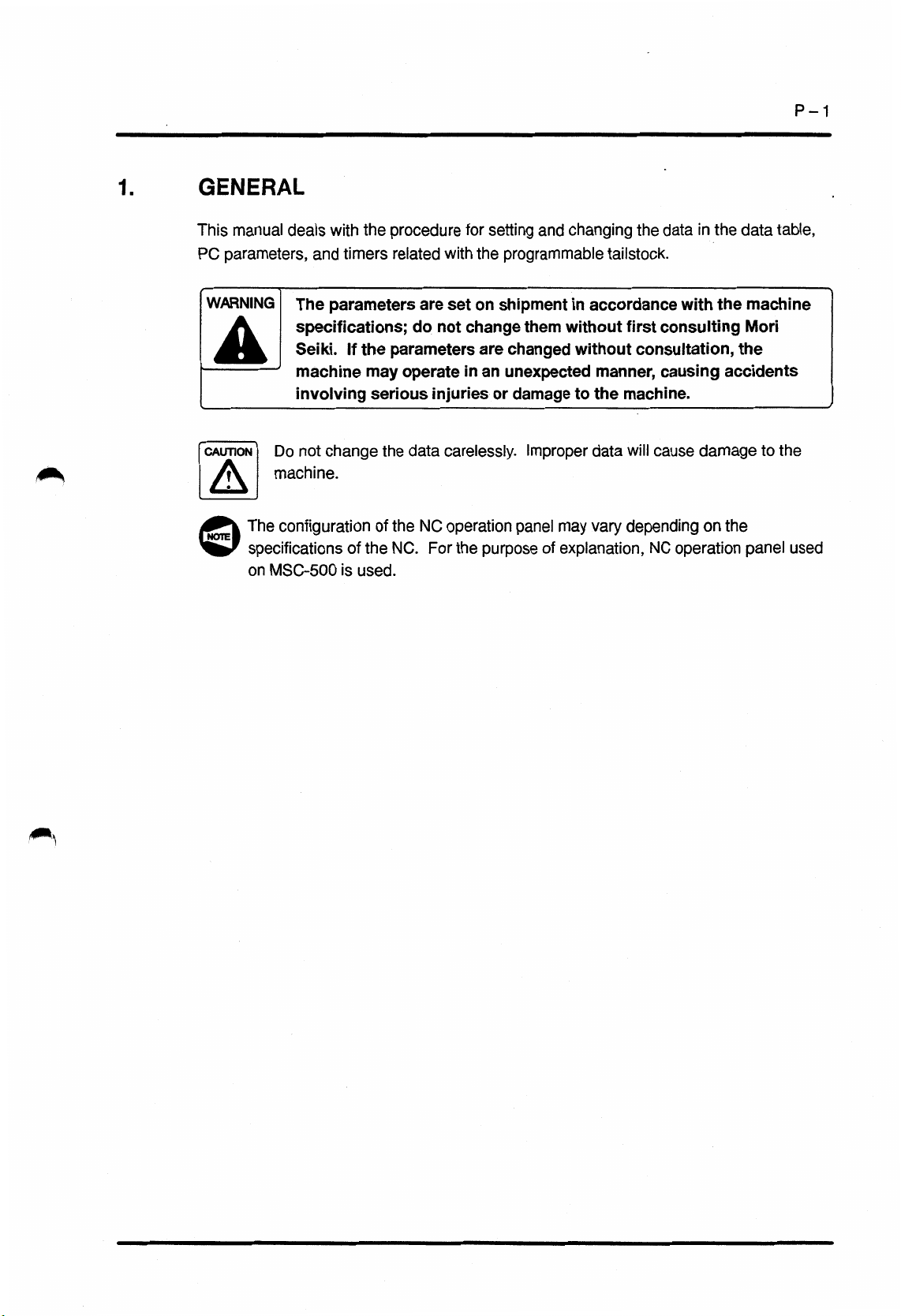
GENERAL
manual
This
PC
parameters,
WARNING
A
CAUTION]
©
deals
The
specifications;
Seiki.
machine
involving
DO
not
machine.
configuration
The
specifications
on
MSC-500
the
with
and
timers
parameters
If
the
may
change
of
the
is
used.
procedure
related
are
do
parameters
operate
serious
the
data
the
NC
of
NC.
for
with
on
set
not
change
in
injuries
carelessly.
operation
the
For
setting
the
are
an
purpose
and
programmable
shipment
them
changed
unexpected
or
damage
Improper
panel
of
changing
tailstock.
in
accordance
without
without
to
may
explanation,
first
manner,
the
machine.
will
data
vary
depending
in
with
damage
the
the
the
data
consulting
consultation,
causing
cause
on
operation
NC
table,
data
machine
Mori
the
accidents
the
to
the
panel
used
Page 6

P-2
2.
PROCEDURE
To
or
set
PANEL
a
OFF
MODE
T>>
°
MEM
EZD
H
KOI
m
“
JOG
change
4
ON
D1
TAPE
D
OAJ
RPD
FOR
the
data
>8>
PANEL
/EDIT
EDIT
CZI
ZRN
SETTING
programmable
for
1)
2)
AND
tailstock,
Place
or
Press
(MDI).
CHANGING
follow
the
PANEL
(PANEL/EDIT)
MODE
the
steps
the
key-switch
selection
THE
indicated
in
position.
switch
DATA
below.
the
[ÿ]
|ÿ[
(ON)
B
POS
0
SYSTEM
ABS
OFFSET
PROG
0
MESSAGE
REL
SETING
B
OFS/SET
GRAPH
ALL
WORK
(B
iBmcoczicncnciiMCDczicz]
(HANDY)
SETTING
(0
0
PARAMETER
TV
CHECK
PUNCH
CODE
INPUT
UNIT
CHANNEL
I/O
SEQUENCE
TAPE
FORMAT
SEQUENCE
SEQUENCE
[CONTRAST]
WRITE
NO.
STOP
STOP
(+
=
-
=
=
=
=
«
=
[ON:
0
1
0
0
0
0
(0
(0:
(0
(0-3
(0
(0
1)
:
:
:
:
:
DISABLE
OFF
EIA
MM
OFF
NO
-
:
CHANNEL
CNV
(PROGRAM
0
(SEQUENCE
0
[OFF:
*
1
1
1
1
1
:
:
ON)
ISO)
:
INCH)
:
:ON)
0])
CUSTOM
(OPRT)
ENABLE)
NO.)
15)
1
:
F
NO.)
NO.
ET|
)
3)
Press
(OFS/SET).
4)
Press
5)
Press
and
(HANDY)
6)
Move
using
the
the
the
[is]
the
the
function
[
SETING
page
selection
(advance)
screen.
cursor
cursor
selection
]
soft-key.
keys
display
to
“PARAMETER
to
control
keys
key
[e]
the
Q~]
[j§[]
(return)
SETTING
WRITE”
and
[T]
.
Page 7

P-3
0000
0
0000
0000
H
0000
0000
0
SnEbi
0U0U
MESSAGE
ALARM
1
PARAMETER
00
000
000
000
000
000
SEES
MMM
WRITE
ENABLE
ALM
0
@
S
6
0
0
7)
8)
the
Press
the
Press
The
data
message
“100
PARAMETER
Q'J
[j>]
setting
displayed:
is
key.
(INPUT)
is
enable
WRITE
key.
when
ENABLE”
the
following
E
POS
ts
SYSTEM
ABS
PARAM
(33
PROG
m
MESSAGE
REL
DGNOS
B
OFS/SET
(hZl
GRAPH
ALL
PMC
IBC3C3IIIIC3C3II3CZI
ONE
SYSTEM
OF
FOLLOWING
MENU
SOFT
DYNAMIC
LADDER
DIAGNOSIS
PARAMETER
RUN/STOP
I/O
SEQUENCE
SEQUENCE
PMC
SELECT
CONTROL
PMCLAD
PMCDGN
PMCPRM
RUN/STOP
I/O
SYSTEM
MPD
KEYS
DISPLAY
FUNCTION
(T/C/K/D)
PROGRAM
CUSTOM
(OPRT)
IT
RUN
MON
PROGRAM
ts]
9)
Press
(SYSTEM).
0)
1
Press
The
is
11
)
Press
The
keep
function
the
[
the
CONTROL
PMG
displayed.
the
[
setting
relays,
selection
PMC
PMCPRM
]
screen
or
the
soft-key.
for
data
key
SYSTEM
soft-key.
]
timers,
the
table
is
Sj
MENU
displayed.
screen
counters,
Page 8

P-4
TiMEfi
Si
0ÿ
B
POS
O
xA
u,
COUNT*
*
CD
zB
TH
S.
K
—
Hi
I2)
PROG
KEEPRL
7*-
Po
Y,
111
1'
V
L
t
/
—
MMM\
i
MMM
EE)
OFS/SET.
DATA
<
11
11
i!
n
9'
8-*
II
-v
CS
CUSTOM
*1,
JL
H
IJILI
2)
1
Press
to
TIMER
t
[
DATA
The
keep
response
3)
1
Move
the
1
4)
Input
15)
Press
1
6)
Set
to
7)
1
After
data,
(OFS/SET).
the
be
set.
setting
relays,
the
data
the
the
or
1
5)
above.
finishing
press
soft-key
],
[
COUNTR
]
screen
the
to
cursor
should
data
g]
change
the
corresponding
],
[
the
for
or
the
pressed
to
be
using
(INPUT)
the
the
function
table
data
soft-key.
the
data
or
set
the
data
key.
by
data
settingorchanging
selection
to
KEEPRL
timers,
counters,
displayed
is
number
changed.
entry
repeating
key
the
],
for
keys.
steps
of
|jj[|
data
in
which
1
2)
the
w
SYSTEM
OFFSET
!яяяяяя
SETTING
PARAMETER
TV
PUNCH
INPUT
I/O
SEQUENCE
TAPE
SEQUENCE
SEQUENCE
[CONTRAST]
C3
ABS
(HANDY)
CHECK
CODE
UNIT
CHANNEL
FORMAT
S
MESSAGE
REL
SETING
WRITE
NO.
STOP
STOP
(+
-
=
=
=
-
-
=
[ON:
GRAPH
ALL
WORK
0
0
1
0
(CHS
0
(0
0
(0
0
1]
(E)
DISABLE
:
OFF
EIA
:
MM
:
OFF
:
NO
-
1
1
:
CHANNEL
1:ON)
CNV
(PROGRAM
0
(SEQUENCE
0
[OFF:
-
1
:
:
1
:
0])
(OPRT)
[ÿ
ENABLE)
:
ON)
ISO)
INCH)
NO.)
F
:
1
r=i
15)
NO.)
NO.
GET]
)
8)
1
19)
20)
Press
the
The
SETTING
Press
the
and
[e]
(HANDY)
Move
the
using
the
[
SETING
screen
page
selection
(advance)
screen.
cursor
cursor
to
control
soft-key.
]
displayed.
is
keys
[a]
display
to
the
“PARAMETER
keys
[T]
(return)
SETTING
WRITE”
and
[7J
w
.
Page 9

P-5
O
(
X»
u
S.
K
7?
s
SrnHrri
SHlH
a?
Co
T*
7'
Po
4*
Y,
V
I*
L
/
FSP
EH®
a®®
8»
5
2«
0
21)
Press
9"
[2
6*
2
1
3'
El
22)
CAUTION
A
-~~J
@
23)
the
Press
the
I
Always
“PARAMETER
parameter
setting
data.
Press
the
alarm
state.
[T]
g]
return
and
g]
key.
(INPUT)
the
WRITE”
change
changing
(RESET)
key.
setting
after
of
key
for
to
to
“0”
finishing
the
parameter
clear
to
disable
the
the
Page 10

P-6
3.
3.1
CLAMP
TAILSTOCK
clamp
The
if
power
memory
If
the
The
©
Resetting
The
<Example>
tailstock
procedure
POSITION
position
area
clamp
cannot
Clamp
to
off)
position
set
Clamp
(coordinate
in
system)
is
turned
the
the
programmable
of
and
is
cleared,
is
data
be
connected
Position
clamp
the
position
machine
the
DATA
updated
necessary
it
is
must
Data
position
<1
values
coordinate
FOR
automatically
be
with
Tailstock
THE
tailstock
to
correctly.
set
the
saddle
data,
for
set
PROGRAMMABLE
body
is
as
the
correctly.
tailstock,
the
writtentothe
the
tailstockismoved.
clamp
position
If
setting
the
is
data
data
incorrect,
is
indicated
table
correctly.
the
below.
(retained
1ÿ0
O
ERR
O
M00/M01
O
M02/M30
O
CHCL
DOOR
NORMAL
STATUS
INTERLOCK
RELEASE
MRDY
•
TRCL
O
OX-!
O
Z
4-
-J
1
2)
3)
)
Place
NORMAL
the
Close
Make
0
the
the
the
Make
MRDY
[
DOOR
position.
door.
front
on-site
that
sure
]
is
INTERLOCK
adjustment
STATUS
the
lit.
key-switch
valid.
mode
indicator
in
w
Page 11

SP
Q
OFF
PANEL
*
ON
PANEL
/EDIT
(2)
Press
and
switch,
follows.
[iÿl
(PANEL/EDIT)
(ON)
[cf]
hold
place
down
PANEL
the
1
position.
the
[ÿ]
key-switch
position.
P-7
(SP)
as
MEM
H
ST
MD!
CD
W0ÿ
JOG
CYCLE
MODE
SP
TAPE
RPO
||F5>
EDIT
ZRN
4)
5)
The
blinks
made
“4”
Set
Press
switches
for
any
indicator
and
valid.
“D1
For
refer
of
showntothe
on-site
49”
the
to
the
above
of
procedure
page
shaded
the
adjustment
the
PC
parameter.
2
P
-
MODE
left.
j®|
mode
used
(2.)
selection
(SP)
for
switch
is
setting,
AXIS
DIRECTION
2
HANDLE
pTifqfq
6)
Move
the
tailstock
moving
feed,
or
saddle
can
the
Z-axis
handle
to
be
connected
with
feed
the
position
rapid
operation.
where
with
the
traverse,
the
saddle
jog
by
z
x
Page 12

P-8
AXIS
DIRECTION
il
TSCLP
CD
TSTMOD
CD
X
1
TSUCLP
HANDLE
F1F1FI
7)
Press
the
The
tailstock
extends
connectedtothe
indicator
The
If
the
lit
not
pressed,
Press
0
tailstock
Move
@
and
8)
making
After
[
TSUCLP
tailstocktothe
selected
handle
[
TSUCLP
is
the
from
in
indicator
when
the
follow
the
[
once.
the
Z-axis
press
sure
]
switch
operation
feed).
]
switch.
unclamped
tailstocksothat
saddle.
[
TSUCLP
the
in
[
the
TSUCLP
[
TSUCLP
procedure
the
TSCLP
the
required
]
the
to
[
TSUCLP
the
that
has
been
position
mode
switch
indicator
(rapid
and
the
it
]
switch
]
switch
below.
to
required
]
switch
lit,
move
in
feed,
joint
is
]
switch
is
clamp
position
in
the
jog
pin
is
lit.
is
the
again.
the
the
feed,
x
TSCLP
TSTMOD
TSUCLP
9)
10)
Press
the
The
tailstock
the
from
The
indicatorinthe
off
lit.
When
position
updated.
Press
The
and
the
the
on-site
the
data
[
TSCLP
clamped;
is
saddle.
indicator
tailstock
storing
for
emergency
adjustment
]
switch.
TSUCLP
[
in
the
clamped,
is
is
stop
mode
is
it
disconnected
]
switch
TSCLP
[
automatically
]
the
connective
button.
is
cleared.
goes
switch
w
is
Page 13

P-9
4.
PCLPOK.
PC
PARAMETERS
TAILSTOCK
This
section
WARNING
A
jT~y3
Address
P
(D125.6)
For
deals
The
specifications;
Seiki.
machine
involving
the
1
:
0:
the
with
parameters
If
the
may
serious
setting
Clamp
(manual
Clamp
(manual
is
is
RELATED
PC
parameters
are
set
do
not
parameters
operate
injuries
parameter,
the
of
enabled
mode)
disabled
mode)
after
after
related
on
shipment
change
are
in
an
or
Z-axis
Z-axis
WITH
changed
unexpected
damage
refer
PROGRAMMABLE
with
in
them
without
without
to
page
to
Description
movement
movement
programmable
the
accordance
first
consultation,
manner,
machine.
the
P
(2.)
2
-
in
the
in
the
with
consulting
causing
positive
positive
tailstock.
the
machine
Mori
the
accidents
direction
direction
TSRPD.
TSJOG.
TSOCOK.
P
(K4.1)
P
P
(K4.3)
(D149.2)
Standard
3
:
1
Rapid
override
unclamped.
Rapid
0:
override
unclamped.
Standard
<3
:
1
Manual
programmable
0:
Manual
tailstock
Standard
<3
1
:
Unclamp
the
tailstock
Unclamp
0:
tailstock
setting
25%
is
50%
is
setting
rapid
traverse
tailstock
rapid
traverse
unclamped
is
setting
enabled
is
connective
is
disabled
connective
“0”.
is
or
lower
or
lower
“0”.
is
is
rate
unclamped.
is
is
rate
while
“0”.
is
even
when
position.
only
when
position.
programmable
while
programmable
while
[m]
to
(fine
the
at
fixed
according
programmable
programmable
the
programmable
the
feed)
rapid
tailstock
tailstock
tailstock
tailstock
tailstock
while
override
unclamped.
is
is
is
is
while
is
not
at
at
the
3
This
Standard
parameter
setting
is
the
“0”.
is
on-site
adjustment
parameter.
Page 14

P-10
Address
NTSDEC.
(ZL
series)
TSCLSIFT.
series)
(ZL
(D279.7)
P
(D281.6)
P
:
1
Tailstock
0:
Tailstock
1
:
Clamp
0:
Unclamp
feed
feed
Standard
Z-axis
with
without
Standard
deceleration
deceleration
setting
setting
is
1
shifted
Z-axis
is
“0”.
1
shifted
“0”.
Description
switch
switchisused.
after
not
is
clamp
after
used.
command
clamp
is
executed.
command
is
executed.
w
w
Page 15

Comment
Form
Date:
19
improve
To
this
manual.
comments
Name
Number
Name
Department
Address
Chapter
this
We
those
to
manual
of
of
manual,
want
concerning
revisions
Page
to
we
know
you
invite
you
how
this
manual
PROGRAMMABLE
SM-PTSMSC51
Line
to
make
think
only.
8-AOE
comments
we
make
can
TAILSTOCK
(1997.12)
Company
Telephone
Comments
any
on
insufficient
this
manual
OPERATION
Requests
/
description
better.
MANUAL
Please
errors
or
restrict
in
your
For
Mori
Seiki’s
use
-
Do
Description
not
write
below
this
line.
Reception
No.
Received
by
Page 16

I
 Loading...