


INSTRUCTION MANUAL
Applicable Model
NH4000 DCG
NH5000
NH5000 DCG
NH6300 DCG
NH8000 DCG
NV4000
Applicable Specification
Carrier Pallet Pool System
Applicable NC Unit
MSG-501 MSG-502
MSX-501 MSX-501III
MSX-502 MSX-502III
MSX-701 MSX-701III
MSX-711 MSX-711III
Before starting operation, maintenance, or programming, carefully read the
manuals supplied by Mori Seiki, the NC unit manufacturer, and equipment
manufacturers so that you fully understand the information they contain.
Keep the manuals carefully so that they will not be lost.
PPM-NHCPP-C1EN

• The contents of this manual are subject to change without notice due to
improvements to the machine or in order to improve the manual.
Consequently, please bear in mind that there may be slight discrepancies
between the contents of the manual and the actual machine. Changes to
the instruction manual are made in revised editions which are
distinguished from each other by updating the instruction manual number.
• Should you discover any discrepancies between the contents of the
manual and the actual machine, or if any part of the manual is unclear,
please contact Mori Seiki and clarify these points before using the
machine. Mori Seiki will not be liable for any damages occurring as a
direct or indirect consequence of using the machine without clarifying
these points.
• All rights reserved: reproduction of this instruction manual in any form, in
whole or in part, is not permitted without the written consent of Mori Seiki.
The product shipped to you (the machine and accessory
equipment) has been manufactured in accordance with the laws
and standards that prevail in the relevant country or region.
Consequently it cannot be exported, sold, or relocated, to a
destination in a country with different laws or standards.
The export of this product is subject to an authorization from the
government of the exporting country.
Check with the government agency for authorization.
990730
SIGNAL WORD DEFINITION
A variety of symbols are used to indicate different types of warning information and advice.
Learn the meanings of these symbols and carefully read the explanation to ensure safe operation
while using this manual.
<Symbols related with warning>
The warning information is classified into three categories, DANGER, WARNING, and CAUTION.
The following symbols are used to indicate the level of danger.
DANGER
WARNING
CAUTION
Indicates a potentially hazardous situation which, if not avoided, may result in minor or
moderate injury or damages to the machine.
The information described following the caution symbol must be strictly observed.
<Other symbols>
Indicates the items that must be taken into consideration.
NOTE
Indicates useful guidance relating to operations.
Indicates an imminently hazardous situation which, if not avoided, will
result in death or serious injury.
The information described in the DANGER frame must be strictly
observed.
Indicates a potentially hazardous situation which, if not avoided, could
result in death or serious injury.
The information described in the WARNING frame must be strictly
observed.
Indicates the page number or manual to be referred to.
The number in ( ) indicates the section number.

CONTENTS
1 OVERVIEW . . . . . . . . . . . . . . . . . . . . . . . . . . . . . . . . . . . . . . . . . . . . . . . . . . . . . . . . . . . P-1
2 SCHEMATIC DIAGRAM OF PALLET POOL SYSTEM. . . . . . . . . . . . . . . . . . . . . . . . . . P-2
3 PALLET TRANSPORT PROCESSING . . . . . . . . . . . . . . . . . . . . . . . . . . . . . . . . . . . . . . P-4
3-1 Pallet Transport Processing Flowchart . . . . . . . . . . . . . . . . . . . . . . . . . . . . . . . . . P-4
3-2 Pallet Transport Flow . . . . . . . . . . . . . . . . . . . . . . . . . . . . . . . . . . . . . . . . . . . . . . P-6
3-3 Urgent Workpieces (Interruption Processing) . . . . . . . . . . . . . . . . . . . . . . . . . . . . P-8
3-3-1 Interruption Method . . . . . . . . . . . . . . . . . . . . . . . . . . . . . . . . . . . . . . . . . P-8
3-3-2 Interruption Operation . . . . . . . . . . . . . . . . . . . . . . . . . . . . . . . . . . . . . . . P-8
4 DATA SETTING SCREENS . . . . . . . . . . . . . . . . . . . . . . . . . . . . . . . . . . . . . . . . . . . . . . P-9
4-1 Screen Trees. . . . . . . . . . . . . . . . . . . . . . . . . . . . . . . . . . . . . . . . . . . . . . . . . . . . . P-9
4-2 PCMDI MENU Screen . . . . . . . . . . . . . . . . . . . . . . . . . . . . . . . . . . . . . . . . . . . . . P-11
4-3 WORK NUMBER Screen . . . . . . . . . . . . . . . . . . . . . . . . . . . . . . . . . . . . . . . . . . P-11
4-3-1 Description of Pallet Statuses . . . . . . . . . . . . . . . . . . . . . . . . . . . . . . . . P-18
4-4 SETUP STATION PALLET CALL Screen . . . . . . . . . . . . . . . . . . . . . . . . . . . . . . P-21
4-5 WORK NUMBER (SUB) Screen . . . . . . . . . . . . . . . . . . . . . . . . . . . . . . . . . . . . . P-22
4-6 PALLET DATA Screen. . . . . . . . . . . . . . . . . . . . . . . . . . . . . . . . . . . . . . . . . . . . . P-23
5 SETUP STATION OPERATION PANEL . . . . . . . . . . . . . . . . . . . . . . . . . . . . . . . . . . . . P-24
5-1 Setup Station Operation Panel . . . . . . . . . . . . . . . . . . . . . . . . . . . . . . . . . . . . . . P-24
5-2 Switches on the Operation Panels . . . . . . . . . . . . . . . . . . . . . . . . . . . . . . . . . . . P-25
5-2-1 EMERGENCY STOP Button . . . . . . . . . . . . . . . . . . . . . . . . . . . . . . . . . P-25
5-2-2 LINK/INDE. Selection Switch . . . . . . . . . . . . . . . . . . . . . . . . . . . . . . . . . P-25
5-2-3 ALARM Indicator . . . . . . . . . . . . . . . . . . . . . . . . . . . . . . . . . . . . . . . . . . P-25
5-2-4 ALARM RESET Switch . . . . . . . . . . . . . . . . . . . . . . . . . . . . . . . . . . . . . P-25
5-2-5 SETUP Switches . . . . . . . . . . . . . . . . . . . . . . . . . . . . . . . . . . . . . . . . . . P-26
6 STARTING THE APC AND PALLET POOL . . . . . . . . . . . . . . . . . . . . . . . . . . . . . . . . . P-27
6-1 Starting with the M02/M30. . . . . . . . . . . . . . . . . . . . . . . . . . . . . . . . . . . . . . . . . . P-27
6-2 Starting with the M60/M61. . . . . . . . . . . . . . . . . . . . . . . . . . . . . . . . . . . . . . . . . . P-28
6-3 Starting Using the APC START Switch (Option) . . . . . . . . . . . . . . . . . . . . . . . . . P-28
6-4 Starting from the SETUP STATION PALLET CALL Screen . . . . . . . . . . . . . . . . P-28
6-5 Starting Using the Buttons on the Setup Station Operation Panel . . . . . . . . . . . P-28
6-6 SYSTEM LINK/INDE. Selection Switch. . . . . . . . . . . . . . . . . . . . . . . . . . . . . . . . P-29

6-7 Operation of the Setup Station . . . . . . . . . . . . . . . . . . . . . . . . . . . . . . . . . . . . . . P-29
6-7-1 Single Pallet Operation . . . . . . . . . . . . . . . . . . . . . . . . . . . . . . . . . . . . . P-29
6-7-2 Multiple Pallet Operation . . . . . . . . . . . . . . . . . . . . . . . . . . . . . . . . . . . . P-29
7 TABLE CLAMP/UNCLAMP FOOTSWITCH AT THE SETUP STATION . . . . . . . . . . . . P-30
8 SETUP STATION DOOR LOCK CONDITIONS . . . . . . . . . . . . . . . . . . . . . . . . . . . . . . P-30
9 AUTOMATIC POWER SHUTOFF . . . . . . . . . . . . . . . . . . . . . . . . . . . . . . . . . . . . . . . . . P-30
10 AUTO-COUPLER (OPTION). . . . . . . . . . . . . . . . . . . . . . . . . . . . . . . . . . . . . . . . . . . . . P-31
10-1 Operating the Auto-coupler . . . . . . . . . . . . . . . . . . . . . . . . . . . . . . . . . . . . . . . . . P-31
11 MAINTENANCE . . . . . . . . . . . . . . . . . . . . . . . . . . . . . . . . . . . . . . . . . . . . . . . . . . . . . . P-31
11-1 Recovering Interrupted Pallet Pool Operation . . . . . . . . . . . . . . . . . . . . . . . . . . . P-31
APPENDIX 1 HANDY OPERATION PANEL . . . . . . . . . . . . . . . . . . . . . . . . . . . APPENDIX-1
1-1 Manual Pallet Pool Operation Mode ON/OFF Switch . . . . . . . . . . . . . . APPENDIX-2
1-2 Emergency Stop Button . . . . . . . . . . . . . . . . . . . . . . . . . . . . . . . . . . . . APPENDIX-3
1-3 Selecting the Operation Mode. . . . . . . . . . . . . . . . . . . . . . . . . . . . . . . . APPENDIX-3
1-4 Registering Position Data of the A.G.V. and the Fork . . . . . . . . . . . . . . APPENDIX-6
APPENDIX 2 OPERATION USING MANUAL OPERATION SCREENS . . . . . . APPENDIX-9
2-1 Pallet Pool Operation Screen . . . . . . . . . . . . . . . . . . . . . . . . . . . . . . . . APPENDIX-9
2-1-1 PCMDI MENU Screen . . . . . . . . . . . . . . . . . . . . . . . . . . . . . . APPENDIX-9
2-1-2 MANUAL OPERATION Menu Screen. . . . . . . . . . . . . . . . . . APPENDIX-10
2-1-3 MANUAL OPERATION Screens . . . . . . . . . . . . . . . . . . . . . . APPENDIX-11
2-1-4 A.G.V. INDEX Screen . . . . . . . . . . . . . . . . . . . . . . . . . . . . . . APPENDIX-13
2-1-5 MAINTENANCE DOOR Screen . . . . . . . . . . . . . . . . . . . . . . APPENDIX-14
2-1-6 ZERO RETURN Screen . . . . . . . . . . . . . . . . . . . . . . . . . . . . APPENDIX-15
2-1-7 STATUS DISPLAY Screen . . . . . . . . . . . . . . . . . . . . . . . . . . APPENDIX-16
2-2 Pallet Pool Operation Using MANUAL OPERATION Screens . . . . . . APPENDIX-17
2-2-1 FORK CENTER Operation . . . . . . . . . . . . . . . . . . . . . . . . . . APPENDIX-19
2-2-2 FORK FORWARD Operation . . . . . . . . . . . . . . . . . . . . . . . . APPENDIX-19
2-2-3 FORK UP/FORK DOWN Operation . . . . . . . . . . . . . . . . . . . APPENDIX-19
2-2-4 SHUTTER OPEN/SHUTTER CLOSE Operation . . . . . . . . . APPENDIX-19

2-3 A.G.V. Indexing Using A.G.V. INDEX Screen . . . . . . . . . . . . . . . . . . . APPENDIX-20
2-4 Maintenance Door Locking/Unlocking Operation . . . . . . . . . . . . . . . . APPENDIX-21
2-4-1 MAINTENANCE DOOR LOCK Operation . . . . . . . . . . . . . . APPENDIX-21
2-4-2 MAINTENANCE DOOR UNLOCK Operation . . . . . . . . . . . . APPENDIX-21
2-5 Zero Return Operation . . . . . . . . . . . . . . . . . . . . . . . . . . . . . . . . . . . . APPENDIX-22
2-5-1 A.G.V. ZERO RETURN Operation . . . . . . . . . . . . . . . . . . . . APPENDIX-22
2-5-2 FORK FOR./BACK ZERO RETURN Operation . . . . . . . . . . APPENDIX-23
2-5-3 A.G.V. + DIRECTION FEED Operation. . . . . . . . . . . . . . . . . APPENDIX-23
2-5-4 A.G.V. − DIRECTION FEED Operation . . . . . . . . . . . . . . . . . APPENDIX-24
2-5-5 FORK FOR./BACK + FEED Operation . . . . . . . . . . . . . . . . . APPENDIX-24
2-5-6 FORK FOR./BACK − FEED Operation . . . . . . . . . . . . . . . . . APPENDIX-25
2-6 Releasing Manual Operation Interlock . . . . . . . . . . . . . . . . . . . . . . . . APPENDIX-26
APPENDIX 3 MAINTENANCE OPERATION . . . . . . . . . . . . . . . . . . . . . . . . . . APPENDIX-27
3-1 Adjustment at Start-up. . . . . . . . . . . . . . . . . . . . . . . . . . . . . . . . . . . . . APPENDIX-27
APPENDIX 4 OPERATION OF AUTO-COUPLER (OPTION) . . . . . . . . . . . . . APPENDIX-29
APPENDIX 5 PC-BASED (MCC-LPS) CONTROL (OPTION) . . . . . . . . . . . . . APPENDIX-30
5-1 Schematic Diagram of Pallet Pool System . . . . . . . . . . . . . . . . . . . . . APPENDIX-30
5-2 Station Numbers . . . . . . . . . . . . . . . . . . . . . . . . . . . . . . . . . . . . . . . . . APPENDIX-31
5-3 Data Table Numbers . . . . . . . . . . . . . . . . . . . . . . . . . . . . . . . . . . . . . . APPENDIX-32
5-4 Parameters . . . . . . . . . . . . . . . . . . . . . . . . . . . . . . . . . . . . . . . . . . . . . APPENDIX-32
1OVERVIEW
The carrier pallet pool system operates according to the priority order determined by the operator
for setup and machining. For an urgent request, the system is able to respond to the request by
allowing the setup and machining for the urgent workpieces by interrupting the predetermined
order.
The system is most appropriate for repetitive production of medium lot with medium variety of
kinds of workpieces.
Since the pallet pool indexing is controlled in the random method, a total of "number of stockers +
1" pallets can be set in the system.
In this instruction manual, "one machine + one setup station + one pallet pool" system with PMC
control is taken as an example for explanations.
P-1
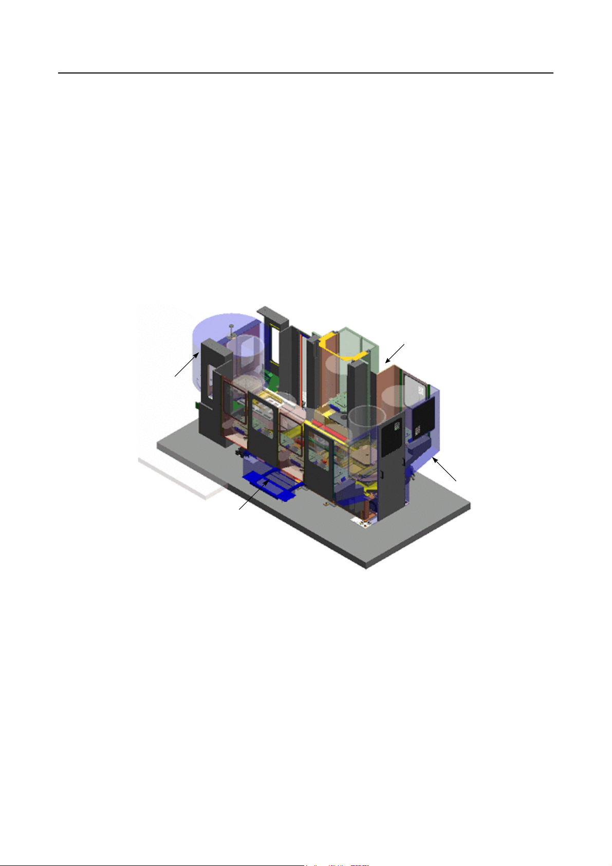
Setup station
Machine setup station
Pallet pool electrical cabinet
Splash guard
Machine image (longitudinal arrangement specification)
P-2
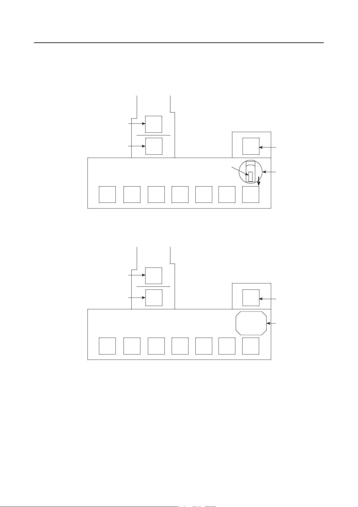
2 SCHEMATIC DIAGRAM OF PALLET POOL SYSTEM
<Layout diagram of 8-station traversal arrangement specification (NH4000 DCG)>
Machine
In-machine station
Standby station
31 34 35 36 37
32
12
11
Pallet
33
01
Setup station
A.G.V.
<Layout diagram of 8-station traversal arrangement specification (NH5000/NH5000 DCG)>
Machine
In-machine station
Standby station
12
11
01
Setup station
31 34 35 36 37
32
33
A.G.V.

P-3
<Layout diagram of 6-station longitudinal arrangement specification (NH5000/NH5000 DCG)>
Standby station
NOTE
34
A.G.V.
35
33
32
01
Setup station
31
11
In-machine station
12
Machine
1. The numbers given in the diagram above indicate the station numbers. Pallet
transport is controlled according to these station numbers.
2. Depending on the system specification, the layout of the machine, stockers and the
setup station may differ from the ones shown above.
3. When loading or unloading a pallet to or from the machine or a station, turn the
A.G.V to the direction of loading or unloading the pallet. (The fork can only be
moved in the positive direction to transfer a pallet.)
<Layout diagram of 6-station traversal arrangement specification (NV4000)>
Machine
In-machine station
Standby station
31 34 35
32
12
11
33
01
Setup station
A.G.V.
P-4
3 PALLET TRANSPORT PROCESSING
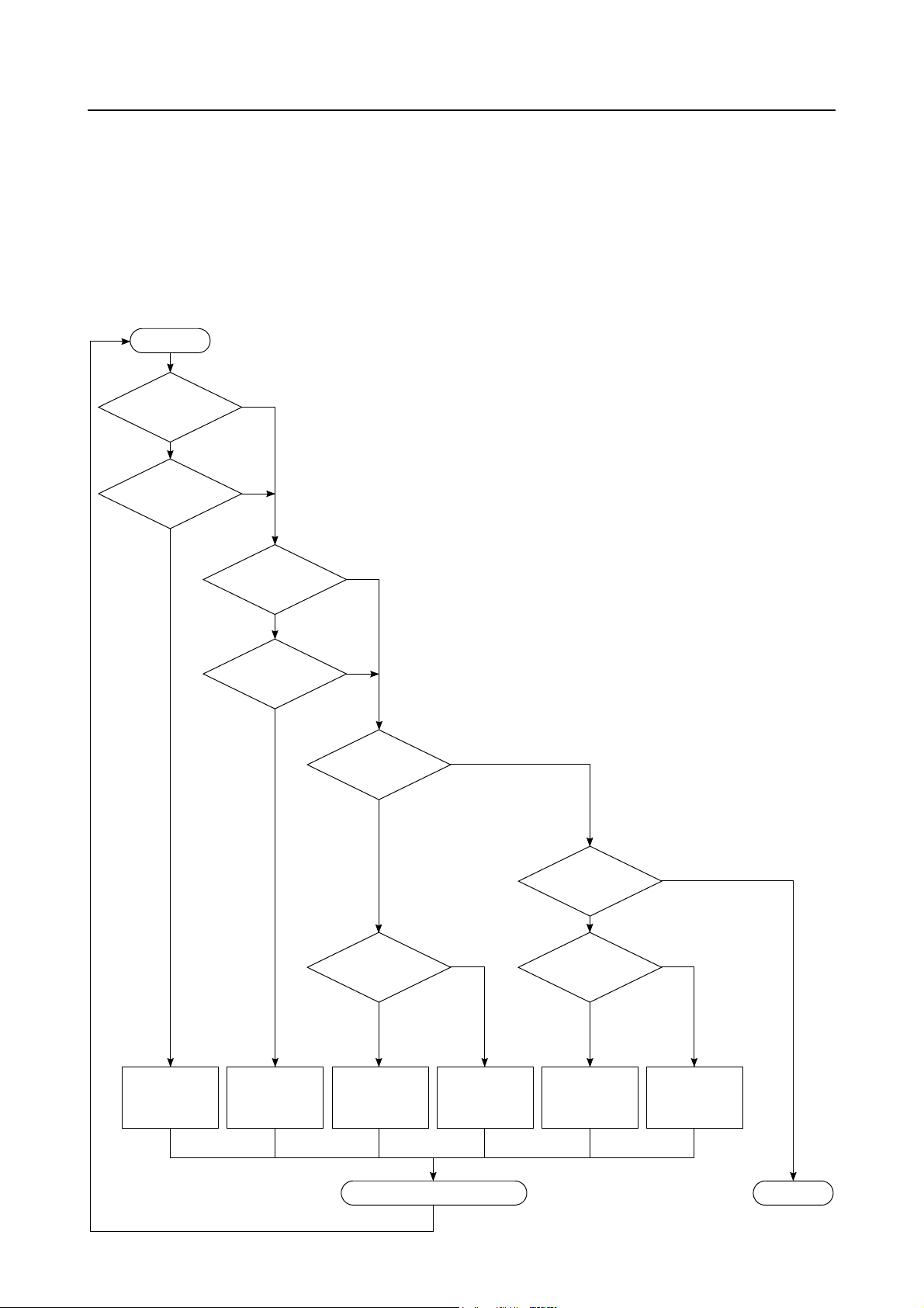
3-1 Pallet Transport Processing Flowchart
A pallet is transported to the stations according to the flowchart given below.
Once the pallet transport processing is started, the pallets are continuously transported according
to the flowchart until the processing is terminated.
START
A pallet in the
standby station?
NO
An S-FIN pallet
in the system?
YES
YES
NO
A pallet in the
setup station?
NO
A C-FIN pallet
in the system?
YES
YES
NO
A C-FIN pallet
in the standby
station?
YES
NO
The S-FIN pallet is
transported to the
standby station.
The C-FIN pallet
is transported to
the setup station.
An empty station
exists?
YES
The C-FIN pallet is
unloaded from the
standby station to
the empty station.
Completion of Loading or Unloading
NO
The C-FIN pallet is
unloaded from the
standby station to
the setup station.
The pallet
in the setup station in
S-FIN status?
YES
An empty station
exists?
YES
The S-FIN pallet is
unloaded from the
setup station to the
empty station.
NO
NO
The S-FIN pallet is
unloaded from the
setup station to the
standby station.
END

P-5
NOTE
1. The S-FIN (setup finished) pallet includes the following pallets.
• The pallet where setup has finished.
• The pallet holding the urgent workpiece; setup has finished.
2. The C-FIN (cutting finished) pallet includes the following pallets.
• The pallet holding the workpiece which has been machined.
• The pallet holding the urgent workpiece which has been machined.
• The pallet holding the defective workpiece.

P-6
3-2 Pallet Transport Flow
The flow of pallet transport is explained.
An example of the pallet transport flow is shown below.
NOTE
No. Operation
1 The A.G.V. moves to the setup station.
Machine
Setup station
2 The setup station shutter is opened.
Stocker
3 The fork advances.
4
Setup station side
Rail
The fork is raised.
When the fork holds a pallet, the A.G.V.
NOTE
leans forward.
To prevent it from leaning forward, the
rail is held and supported.
The rail is supported.
5 The fork retracts.
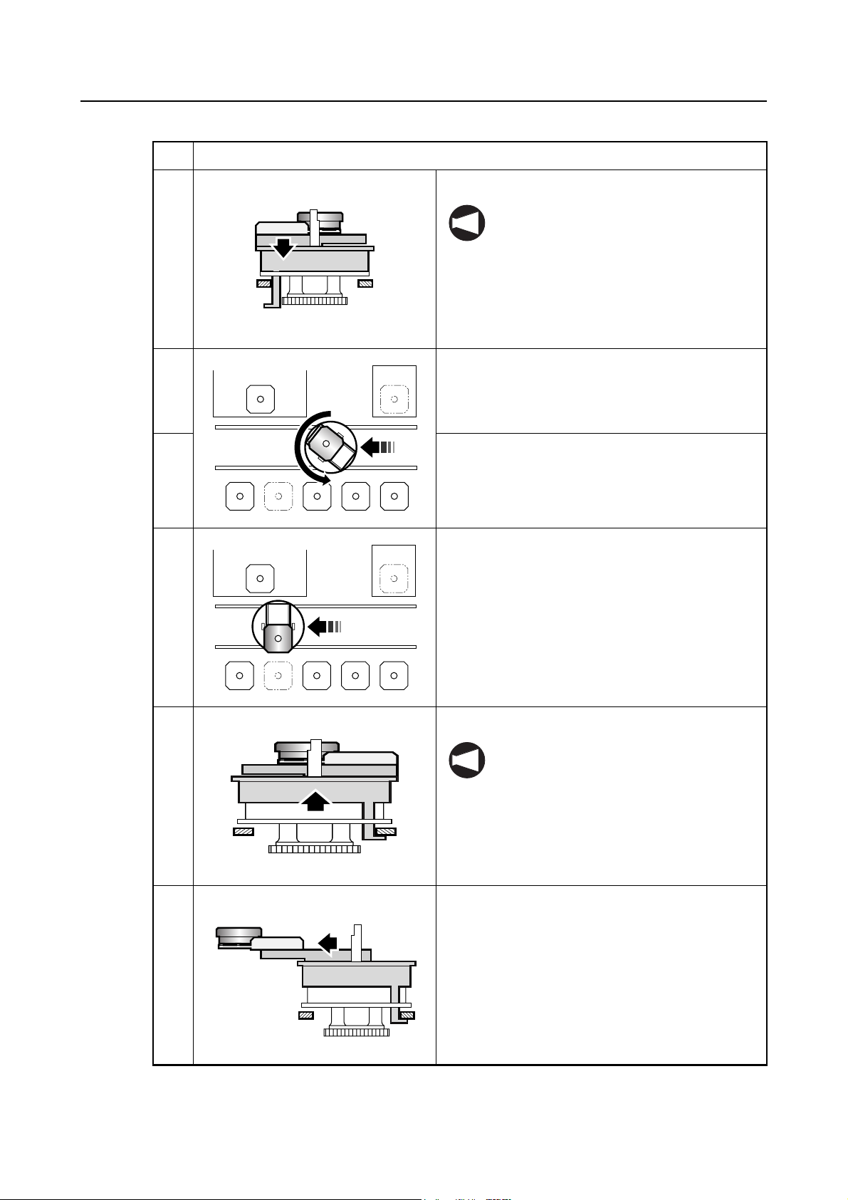
No. Operation
6 The fork is lowered.
The A.G.V. cannot move without
NOTE
releasing the rail.
Therefore, the fork must be lowered.
7 The setup station shutter is closed.
8 The A.G.V. moves.
• The pallet is moved while rotating 180
degrees.
P-7
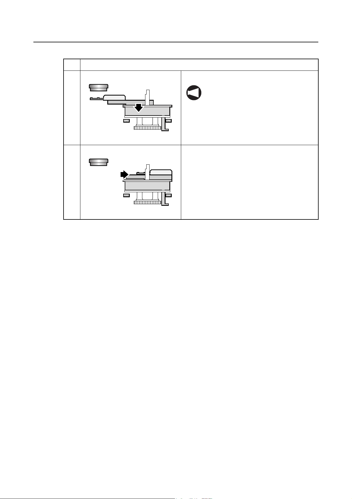
9 The A.G.V. stops in front of the stocker.
10 The fork is raised.
When the fork holds a pallet, the A.G.V.
NOTE
leans forward.
To prevent it from leaning forward, the
rail is held and supported.
11 The fork advances.
Stocker side
P-8
No. Operation
12 The fork is lowered.
The A.G.V. cannot move without
NOTE
releasing the rail.
Therefore, the fork must be lowered.
13 The fork retracts.
3-3 Urgent Workpieces (Interruption Processing)
3-3-1 Interruption Method
When the PRIORITY switch on the setup station operation panel is pressed, the "urgent request
(EXPRES)" is assigned for the pallet presently located at the setup station. Once the "urgent
request (EXPRES)" is assigned, the pallet is given the top priority to be transported to the
machining center and after the completion of machining, it is also given the top priority to be
returned to the setup station.
The "urgent request (EXPRES)" flag is cleared when the pallet is returned to the setup station
again.
Setting of the "urgent request (EXPRES)" is also possible at the WORK NUMBER screen by
setting the "urgent request (EXPRES)" flag at the STATUS column.
3-3-2 Interruption Operation
When the "urgent request (EXPRES)" is set, interruption operation is executed for pallet transport
processing.
After the completion of presently executed pallet transport processing, pallet transport is executed
for the pallet assigned the "urgent request (EXPRES)" flag. Then, upon completion of pallet
transport for urgent request, the processing is continuously executed following the processing
having been executed before interruption.
If the status of the pallet assigned the "urgent request (EXPRES)" is C-FIN, the pallet is
transported to the setup station, and if it is S-FIN, the pallet is transported to the machining center
(standby station).

4 DATA SETTING SCREENS
The data necessary for pallet pool system is set on the screens.
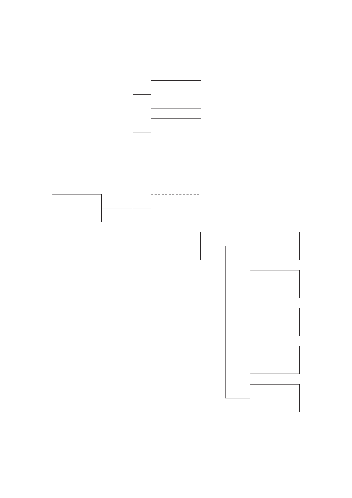
4-1 Screen Trees
<Machine side>
P-9
OPERATION
PANEL screen
SET-UP screen
PCMDI MENU
screen
TOOL ENTRY
screen
ATC MANUAL
screen
PALLET DATA
screen
APC MANUAL
screen
SENSOR
SETTING screen
P-10
<Pallet pool side>
WORK
NUMBER screen
SETUP STATION
PALLET CALL
screen
WORK NUMBER
(SUB) screen
PCMDI MENU
screen
BLOCK DELETE
screen
MANUAL
OPERATION
screen
MANUAL
OPERATION
screen
A.G.V. INDEX
screen
MAINTENANCE
DOOR screen
ZERO RETURN
OP. screen
STATUS
DISPLAY screen

4-2 PCMDI MENU Screen
P-11
[PCMDI MENU]
1 WORK NUMBER
2 SETUP STATION PALLET CALL
3 WORK NUMBER (SUB)
4
5 MANUAL OPERATION
KEY IN NO.
NUM =
Fig. 1
4-3 WORK NUMBER Screen
On this screen, the following information is checked, registered, or changed for each pallet.
Order of machining, setup order, pallet number, station (stocker) number, program number, and
pallet status
[WORK NUMBER] ACT_No. M: 06 W: 05
No. <PLT> <ST> <WORK> <STATUS> <SUB>
1 01 12 1001 CUTING EXPRES
2 02 31 1002 C-FIN
3 03 32 1003 S-FIN
4 04 1 1004 SETING
5 05 33 1005 S-FIN EXPRES
6 06 11 1006 S-FIN ST-HD
Press the function selection key (PRG-SEL/
CUSTOM) on the MDI operation panel at the pallet pool
side.
This displays the PCMDI MENU screen (Fig. 1).
After keying in the number of the menu item for which
data should be set, press the (INPUT) key.
The screen used for setting the selected item is displayed.
On the PCMDI MENU screen (Fig. 1), press the following
keys in order:
(INPUT)
The WORK NUMBER screen is displayed.
NUM =
Fig. 2

P-12
<Description of the soft-keys>
[EXIT]
When this soft-key is pressed, the screen returns to the PCMDI MENU screen.
[CLEAR]
This soft-key can clear either the machining priority data or all data.
When the [CLEAR] soft-key is pressed, the soft-keys shown in Fig. 3-1 are displayed for the
selection of type of data to be cleared. Upon selection of the type of data to be cleared, the
soft-keys shown in Fig. 3-2 or Fig. 3-3 are displayed; pressing the [YES] soft-key clears the
selected data. Press the [NO] soft-key when the data should not be cleared.
SELECT TO KIND OF DATA
CUT-NO ALLCLR CANCEL
Fig. 3-1 Soft-keys for Data Clear Operation 1
CUTTING NUMBER CLEAR OK? (YES/NO)
YES NO
Fig. 3-2 Soft-keys for Data Clear Operation 2
WORK DATA ALL CLEAR OK? (YES/NO)
YES NO
Fig. 3-3 Soft-keys for Data Clear Operation 3

P-13
[ACT_NO]
By pressing this soft-key, it is possible to change the data of "M: " (machining priority number)
and "W: ××" (setup priority number) of ACT_NO.
When the [ACT_NO] soft-key is pressed at the WORK NUMBER screen (Fig. 2), the soft-keys
shown in Fig. 4 are displayed. Key in the "M: " or "W: ××" number to be changed and press
the corresponding soft-key ([M/C] soft-key for changing the machining priority number "M: "
and [WSS] soft-key for changing the setup priority number "W: ××"). If the priority number is not
changed, press the [CANCEL] soft-key.
When changing the number, it is not allowed to input a number greater than the registered
NOTE
maximum machining priority number.
When the power is turned off, both "M: " and "W: ××" are reset to "0".
M/C WSS CANCEL
Fig. 4 Priority Number Setting Soft-keys
[SET]
This soft-key is used to change the <STATUS> (pallet status) or <SUB> (pallet sub status) data.
Pallet transport destination (machining center, setup station, stocker) is determined according to
the pallet status and the pallet sub status. The pallet transport processing for the pallet and pallet
sub statuses is described later.
On the WORK NUMBER screen (Fig. 2), press the [SET] soft-key after moving the cursor to the
<STATUS> item, and the soft-keys shown in Fig. 5 are displayed.
S-FIN C-FIN SETING CUTING CLEAR
Fig. 5 Pallet Status Setting Soft-keys
On the WORK NUMBER screen (Fig. 2), press the [SET] soft-key after moving the cursor to the
<SUB> item, and the soft-keys shown in Fig. 6 are displayed.
EXPRES CUT-HD CLEAR
Fig. 6 Pallet Sub Status Setting Soft-keys
P-14
[N-SORT]
When this soft-key is pressed while the data is shown at random in terms of machining priority
numbers, the data is arranged in the ascending order of machining priority numbers.
The soft-keys shown in Fig. 7 are displayed when the continuous menu key [+] is pressed on the
WORK NUMBER screen (Fig. 2).
N-SORT CHANGE
Fig. 7 [N-SORT] and [CHANGE] Soft-keys
[CHANGE]
By using this soft-key, it is possible to change the machining reserved status pallets (CUT-HD) to
the S-FIN status pallets in batch.
When the [CHANGE] soft-key is pressed, the soft-keys shown in Fig. 8 are displayed. Press the
[YES] soft-key to execute global change. To cancel the operation, press the [NO] soft-key.
DATA CHANGE OK?
YES NO
Fig. 8 Change Function Soft-keys

<Details of the items>
<ACT_NO M: W: ××>
<M: >
The machining priority number of the pallet which is or which has been at the standby
station.
Transport of the S-FIN pallets to the standby station (machine) is controlled based on this
number.
For the procedure used for changing this number, refer to <Description of the
soft-keys> on page P-12.
<Example: M: 04>
The system executes "search" for the S-FIN status pallets in the ascending order of the
machining priority numbers beginning with "5". If a S-FIN pallet is found, that pallet is
transported to the standby station. As soon as the pallet transport begins, the data for
ACT_NO is updated to "M: 06", for example if the machining priority number of the
transported pallet is "6".
P-15
If no S-FIN status pallet is found when search is made up to the pallet assigned the largest
machining priority number, the search is repeated from the smallest machining priority
number. If no S-FIN status pallet is found in this search, executed to the machining priority
number of "3", pallet transport processing is not executed.
The ACT_NO data is not changed if interruption processing for the urgent request is being
NOTE
executed.
<W: ××>
The setup priority number of the pallet which is or which has been at the setup station.
Transport of such a pallet as the C-FIN status pallet and NG status pallet to the setup station
is controlled based on this number.
For the procedure used for changing this number, refer to <Description of the
soft-keys> on page P-12.
<Example: W: 04>
The system executes "search" for the pallets such as C-FIN status pallets which should be
transported to the setup station in the ascending order of the machining priority numbers
beginning with "5". If such a pallet is found, that pallet is transported to the standby station.
As soon as the pallet transport begins, the data for ACT_NO is updated to "W: 06", for
example if the machining priority number of the transported pallet is "6".
If C-FIN status pallet or pallets in the status to be transported to the setup station are not
found when search is made up to the pallet assigned the largest machining priority number,
the search is repeated from the smallest machining priority number. If no pallet to be
transported to the setup station is found in this search which is executed to the machining
priority number of "3", pallet transport processing is not executed.
The ACT_NO data is not changed if interruption processing for the urgent request is being
NOTE
executed.

P-16
<NO.>
Displays the machining priority number.
• Setting is possible in the range from 0 to 99.
• The machining priority number must be unique and it is not allowed to set the same
number for more than one pallet.
<PLT>
Displays the pallet number.
• Setting is possible in the range from 0 to 99.
• The pallet number must be unique and it is not allowed to set the same number for
more than one pallet.
<ST>
Displays the station number of the station where the pallet is stored.
• The station number must be unique and it is not allowed to set the same number for
more than one pallet.
• The number assigned to an empty station cannot be used.
• Setting should be made using the following numbers:
1: Setup station
11: Standby station
12: In-machine station
31: Stocker number 31
32: Stocker number 32
<WORK>
Displays the program number corresponding to the individual pallets <PLT>.
• This number indicates a program number of the program used for machining the
workpiece(s) mounted on the pallet. Setting is possible with up to a four-digit number.
<STATUS>
Displays the status of the individual pallets.
• To change the present setting for <STATUS>, move the cursor to the <STATUS>
column and press the [SET] soft-key, then the status setting soft-keys are displayed.
Press the required one for changing the status.
• When changing the <STATUS> data, entry of a pallet status is not possible unless the
station number is set for the pallet for which the status should be changed.
• The following four status items are provided:
S-FIN, C-FIN, CUTING, and SETING
• For the display of <STATUS> items for the individual pallet statuses, refer to Table 1.

<SUB>
Displays the sub information of the individual pallet status items.
• To change the present setting for <SUB>, move the cursor to the <SUB> column and
press the [SET] soft-key, then the sub status setting soft-keys are displayed. Press
the required one for changing the status.
• The sub status includes the following. Note that it is not possible to set "NG" in this
screen.
EXPRES, CUT-HD, and NG
• For setting the sub status of "EXPRES", the <STATUS> item must be either "S-FIN" or
"C-FIN".
• For setting the sub status of "CUT-HD", the <STATUS> item must be "S-FIN".
• For the display of <SUB> items for the individual pallet statuses, refer to Table 1.
P-17

P-18
4-3-1 Description of Pallet Statuses
The pallet pool controls pallet transport according to the status of a pallet.
Table 1 shows the pallet statuses and the corresponding STATUS and SUB items displayed on the
screen. The pallet transport processing for the individual pallet statuses is explained below the
table.
Table 1 Pallet Status and Display
Pallet Status
Display Items
<STATUS> <SUB>
Setup finished pallet S-FIN
Machining finished pallet C-FIN
Machining hold pallet S-FIN CUT-HD
Urgent request pallet with unmachined workpiece S-FIN EXPRES
Urgent request pallet with machined workpiece C-FIN EXPRES
Pallet with workpiece being machined (in-machine) CUTING
Urgent request pallet with workpiece being machined
(in-machine)
CUTING EXPRES
Setup pallet (setup station) SETING
Error pallet with workpiece being machined CUTING NG
Error pallet with machined workpiece C-FIN NG
Error pallet loaded to setup station SETING NG
Empty pallet
The <STATUS> item of the pallet which is located at the standby station (station number
NOTE
11) lights.
<Pallet status>
1. Setup finished pallet
This indicates the status in which all workpieces and related parts are mounted to the fixture
and setup is completed.
If necessary conditions are satisfied, the pallet is transported to the machining center and
machining starts for the mounted workpieces.
Setting of this status is possible either at the WORK NUMBER screen or the setup station
operation panel.
2. Machining finished pallet
When the APC is executed after the completion of machining (completed correctly), the
pallet status is automatically changed to this status.
The pallet assigned this status is transported to the stocker or the setup station.
In addition to automatic setting as indicated above, it is also possible to set this status at the
WORK NUMBER screen.

P-19
3. Machining hold pallet
This indicates the status in which machining should not be started although setup has been
finished (hold status).
The pallet in this status is transported to the stocker but not to the machine or setup station.
Setting of this status is possible either at the WORK NUMBER screen or the setup station
operation panel.
4. Urgent request pallet
If this status is assigned, interruption processing is executed independent of the present
machining priority number or setup priority number.
Setting of this status is possible either at the WORK NUMBER screen or the setup station
operation panel.
When setting this status at the WORK NUMBER screen, the <STATUS> of that pallet must
be either "S-FIN" or "C-FIN".
5. Machining pallet
This indicates the status in which the pallet is loaded into the machine and machining
program is presently executed.
When the pallet is loaded to the machine, the pallet status is automatically changed to this
status.
In addition to automatic setting as indicated above, it is also possible to set this status at the
WORK NUMBER screen.
On-screen setting is possible only when the <ST> (station number) of this pallet is "12".
NOTE
6. Setting pallet
This indicates the status in which the pallet is loaded to the setup station and setup is being
carried out for that pallet.
When the pallet is loaded to the setup station, the pallet status is automatically changed to
this status.
In addition to automatic setting as indicated above, it is also possible to set this status at the
WORK NUMBER screen.
On-screen setting is possible only when the <ST> (station number) of this pallet is "1".
NOTE

P-20
7. Error pallet
This indicates that the machined workpieces held in the pallet are defective.
Make a program so that "1" is set for #1105 if the result of measurements accomplished by
such as a sensor is defective.
O××××;
#1105 = 1;
G4 X5.;
#1105 = 0;
Once the "NG" display is given while the workpiece is inside the machine, it remains
displayed until the pallet is loaded to the setup station and then unloaded from it.
Although it is possible to clear the "NG" display on the screen, setting the "NG" status is not
possible.
8. Empty pallet
Empty status is set for pallets which will not be used.
The pallet assigned the empty status is unloaded to the stocker and, after the unloading to
the stocker such pallet is not transported to the setup station or the standby station until the
status is changed on the screen.

4-4 SETUP STATION PALLET CALL Screen
By the operation on the SETUP STATION PALLET CALL screen, it is possible to call a pallet to the
setup station.
[SETUP STATION PALLET CALL]
CALLED PALLET NO. 00
SET PALLET NO.
THEN PRESS [EXEC.] SOFT KEY
NUM =
Fig. 9
For transporting a pallet to the setup station, the following conditions must be satisfied.
On the PCMDI MENU screen (Fig. 1), press the following
keys in order:
(INPUT)
The SETUP STATION PALLET CALL screen is displayed.
When the [EXIT] soft-key is pressed, the screen returns to
the PCMDI MENU screen.
After keying in the pallet number of the pallet to be
transported to the setup station, press the [EXEC.]
soft-key and the specified pallet is transported to the
setup station.
P-21
1. The setup station table is at the zero point.
2. The setup station door is closed.
3. Neither pallet transport cycle nor APC cycle is executed.
4. The fixture in the setup station is in the clamped state (auto-coupler specification).
The pallet call operation is possible independent of the setting of the LINK/INDE. selection
NOTE
switch on the setup station operation panel.

P-22
4-5 WORK NUMBER (SUB) Screen
On the WORK NUMBER (SUB) screen, the station number of empty station is set.
[WORK NUMBER (SUB)]
EMPTY STATION 1 0031
EMPTY STATION 2 0036
NUM =
Fig. 10
<Data registration method>
After moving the cursor to the number of the data item to be changed, key in the required number
and press either the [SET] soft-key or the (INPUT) key.
If the [CLEAR] soft-key is pressed, "NONE" is displayed.
After moving pallets in manual operation, make sure to check the EMPTY STATION data whether
it is correct. Change the registration if necessary.
On the PCMDI MENU screen (Fig. 1), press the following
keys in order:
(INPUT)
The WORK NUMBER (SUB) screen is displayed.
When the [EXIT] soft-key is pressed, the screen returns to
the PCMDI MENU screen.
Set the weekly timer work number at the WORK NUMBER screen of the machining center.
NOTE
<EMPTY STATION number>
An empty station number means the number of the stocker where a pallet is not stored.
Setting: 31 and above
CAUTION
Empty station number must not be changed unless necessary for the purpose of
maintenance.
Usually, the empty station number is automatically updated as pallets are transported.
The numbers registered as <ST> number on the WORK NUMBER screen cannot be set.
Setting is possible for up to two station numbers.
If there is no empty station, "NONE" is displayed.

4-6 PALLET DATA Screen
On the PALLET DATA screen, whether a pallet exists in the machining center or not is set.
Usually, the setting is "ON" which means that a pallet exists in the machining center.
Change the setting to "NONE" if there is no pallet in the machining center.
[PALLET DATA]
MACHINE PALLET : NONE ON
NUM =
Fig. 11
P-23
Input the code number of the PALLET DATA screen at the
PCMDI MENU screen of the machining center and press
the (INPUT) key.
INPUT
The PALLET DATA screen is displayed.
Setting can be changed by using the cursor control keys.
When the [EXIT] soft-key is pressed, the screen returns to
the PCMDI MENU screen.
The PALLET DATA screen is the machining center
NOTE
side screen.

P-24
5 SETUP STATION OPERATION PANEL
5-1 Setup Station Operation Panel
5-2-5 "SETUP Switches"
5-2-3 "ALARM Indicator"
5-2-2 "LINK/INDE. Selection Switch"
SETUP
READY NO SET
PRIORITY RESERVE
Arrangement of the switches on the operation panel will differ from the panels shown
NOTE
above.
ALARM LINK INDE.
EMERGENCY
STOP
ALARM
RESET
5-2-1 "EMERGENCY STOP Button"
5-2-4 "ALARM RESET Switch"

5-2 Switches on the Operation Panels
5-2-1 EMERGENCY STOP Button
The EMERGENCY STOP button has the same function as provided by the emergency stop button
on the machine operation panel. Entire system operation stops when this EMERGENCY STOP
button is pressed.
Press this button when stopping the pallet pool and the machine.
5-2-2 LINK/INDE. Selection Switch
When this switch is placed in the LINK position, a pallet is automatically transported to the setup
station. A pallet is not transported to the setup station if the switch is placed in the INDE. position.
Calling a pallet to the setup station using the SETUP STATION PALLET CALL screen is always
possible independent of the setting of the LINK/INDE. selection switch.
Pallet transport from the setup station is also possible independent of the setting of the LINK/
INDE. selection switch.
P-25
5-2-3 ALARM Indicator
The [ALARM] indicator is lit only when an alarm related with the pallet pool occurs.
5-2-4 ALARM RESET Switch
If this switch is pressed after an occurrence of a pallet pool related alarm, the alarm is cleared.
Pallet transport does not stop even when this button is pressed while a pallet is being transported.

P-26
5-2-5 SETUP Switches
The following four SETUP switches are provided:
READY, PRIORITY, NO SET, and RESERVE
To unload a pallet from the setup station to transport it to a stocker or the machining center after
the completion of setup or removal of a finished product at the setup station, press any of the
following switches:
READY, PRIORITY, NO SET, and RESERVE
If any of these switches is pressed when the following conditions are satisfied, the indicator in the
switch is lit. After the completion of pallet unloading from the setup station, the indicator goes off.
If the indicator is not lit and pallet unloading does not start even when the switch is pressed, check
the following conditions if all of them are satisfied.
If the switch, which has been pressed, is pressed again while the indicator is lit and before the
pallet unloading has not started from the setup station, the indicator goes off and pallet unloading
request is canceled. Pressing any other switch causes the indicator in the pressed switch to be lit
and the pallet is unloaded from the setup station under the state corresponding to the pressed
switch. Once the pallet unloading cycle starts, pressing the switch is ignored and the started cycle
is continuously executed even if the switch is pressed.
<Conditions>
The switch is valid when the following conditions are satisfied.
1. There is a pallet in the setup station.
2. The setup station table is at the zero point.
3. The setup station door is closed.
4. There is no error alarm occurred related with the pallet pool.
5. A pallet loading/unloading cycle is not executed at the setup station.
6. The fixture in the setup station is in the clamped state. (Auto-coupler specification)
<READY switch>
Press this switch to transport the pallet, which has been unloaded to the setup station, to the
stocker or the machining center after finishing the setup for that pallet.
<PRIORITY switch>
Press this switch to carry out machining for the urgent request pallet by interruption processing.
The pallet for which this switch is pressed is registered as the urgent request pallet and it is
transported to the machining center at the highest priority after the completion of present
machining.
<NO SET switch>
Press this switch to store a pallet which is not used to the stocker.
Once this flag is set for the pallet, the pallet stays stored in the stocker until the flag is changed on
the screen.
<RESERVE switch>
Press this switch for the pallet which should be stored to the stocker after the completion of setup
without conducting machining.

6 STARTING THE APC AND PALLET POOL
Once pallet indexing is started, pallet transport is continuously executed until there is no pallet to
be transported to the standby station, setup station, stocker, etc. The pallet transport is controlled
according to the flowchart given in 3-1 "Pallet Transport Processing Flowchart".
If pallet transport is started on the SETUP STATION PALLET C A L L s creen, only the specified
pallet is called to the setup station and no further pallet transport is executed.
6-1 Starting with the M02/M30
When the M02/M30 command specified in a program is read in memory mode operation with the
Z-axis at the 2nd zero point and the B-axis at the zero return position, the pallet assigned the
highest priority for machining is selected among the S-FIN status pallets and transported to the
standby station; APC cycle is then executed. After the completion or at the start of APC cycle, the
program to be used for machining of workpiece(s) mounted on that pallet is searched and
automatic operation is started.
The pallet unloaded from the machining center is assigned either the C-FIN status or NG status
and transported to the setup station or the stocker. After the completion of transport of the pallet
unloaded from the machining center, the system searches the setup finished (S-FIN) status pallet
to be machined next and transports it to the standby station.
If there is no S-FIN status pallet when the M02/M30 command is read, the system searches the
pallet to be loaded to or unloaded from the setup station to execute transport processing.
<Example program>
P-27
O1234;
G91;
G28 B0;. . . . . . . . . . . . . . . . . . . . . . . . . B-axis zero return
G30 Z0;. . . . . . . . . . . . . . . . . . . . . . . . . Z-axis 2nd zero return
M02 (M30); . . . . . . . . . . . . . . . . . . . . . . (Pallet change cycle, work number search)

P-28
6-2 Starting with the M60/M61
When the M60/M61 command is read, the pallet given the highest priority among the S-FIN status
pallets is transported to the standby station and APC cycle is executed.
The M60/M61 command (pallet change) can be specified only in the MDI mode.
<M60/M61 valid conditions>
1. The M60/M61 command cannot be specified in the memory or tape mode.
2. When pallet change operation is executed in the memory mode, work number search is
executed either at the completion of pallet change cycle or at the start of it. However, if
pallet change cycle is executed in response to the M60/M61 command, work number search
is not executed.
3. If M60/M61 command is executed while there is no S-FIN status pallet, an alarm occurs.
6-3 Starting Using the APC START Switch (Option)
Pallet change cycle can be started by pressing the APC START switch on the machine operation
panel.
The switch has completely the same function as the M02 (M30) command specified in a program.
For the operation using this switch, the following interlocks are provided.
<APC START switch valid conditions>
1. Memory mode is selected.
2. The system is not in the program cycle start state.
3. The APC is not operating.
If there is no S-FIN status pallet when the APC START switch is pressed, the system searches the
pallet to be loaded to or unloaded from the setup station to execute transport processing.
6-4 Starting from the SETUP STATION PALLET CALL Screen
It is possible to call the required pallet to the setup station by using the SETUP STATION PALLET
CALL screen.
6-5 Starting Using the Buttons on the Setup Station Operation Panel
The SET FIN or NO SET button on the setup station operation panel can be used for starting the
pallet transport operation.
When an S-FIN status pallet is transported to the standby station by the pressing of the button,
APC cycle is not executed after the pallet is transported to the standby station. Even in this case,
if the M02/M30 indicator is lit, the APC cycle is executed.

6-6 SYSTEM LINK/INDE. Selection Switch
P-29
SYSTEM
LINK INDE.
6-7 Operation of the Setup Station
6-7-1 Single Pallet Operation
When repeating setup and machining of workpieces only with a single pallet, operate by the
following method.
• Use another pallet as a dummy pallet and run a program consisting of M02 (M30).
6-7-2 Multiple Pallet Operation
Workpieces on multiple pallets are machined in order of pallet unloading from the setup station.
The pallets are automatically returned to the setup station. Remove the finished workpieces from
the pallet, set up unmachined workpieces, unload the pallet from the setup station, and carry out
machining as described below.
The switch is provided at the machine operation panel.
LINK: Pallets are automatically transferred into the
machine.
INDE.: Automatic transfer of pallets into the machine is
not possible.
1) Check that the shutter between the setup station and the A.G.V. is closed.
2) Turn the handle at the right door of the setup station 45° to the right to unlock the door.
3) Open the right door and then the left door, and remove the finished workpieces.
Turn the table if necessary.
The table can be turned as described below.
a) Step on the foot switch to unclamp the table.
b) Turn the table to the desired direction (at every 45°) and step on the foot switch again
to clamp the table.
4) Set up unmachined workpieces.
5) Align the table to the zero point (shown with an arrow in red) and step on the foot switch to
clamp the table.
6) Close the left door and then the right door.
7) Turn the handle at the right door 45° to the left to lock the door.
8) Press any of the READY, PRIORITY, NO SET or RESERVE switch.
9) Repeat 2) to 8).
When carrying out unmanned operation, store the pallets loaded with workpieces to be
machined temporarily in the stocker by pressing the RESERVE switch. Press the
[CHANGE] soft-key to change the machining reserved pallets to the setup finished pallets
at one time and start unmanned operation.

P-30
7 TABLE CLAMP/UNCLAMP FOOTSWITCH AT THE SETUP
STATION
The footswitch is used to operate the table lock pin at the setup station.
When the footswitch is stepped on while the table is clamped, the table is unclamped. Conversely,
if the footswitch is stepped on while the table is unclamped, the table is clamped.
After completing setup, clamp the table at the home position.
The buttons and switches on the setup station operation panel are invalid unless the table is
clamped at the home position.
<Footswitch valid conditions>
1. The setup station door is open.
2. Pallet loading/unloading cycle is not executed at the setup station.
8 SETUP STATION DOOR LOCK CONDITIONS
The following five combinations of the setup station door lock conditions are provided.
The setup station door is locked when it is closed in the following cases.
1. Pallet loading/unloading cycle is executed at the setup station.
2. There is no pallet in the setup station.
The LINK/INDE. selection switch on the setup station operation panel is placed in the LINK
position.
3. There is a pallet in the setup station.
The indicator in the SET FIN or NO SET button on the setup station operation panel is lit.
4. The setup station shutter is opened.
5. The pallet pool is in the manual (ON) mode.
(The manual pallet pool operation mode ON/OFF switch is provided on the handy operation
panel.)
9 AUTOMATIC POWER SHUTOFF
By executing automatic power shutoff at the machine, automatic power shutoff is executed at the
pallet pool.
The automatic power shutoff function becomes valid under the condition that there is no S-FIN
status pallet at the stocker, setup station, and standby station.
Whether or not the automatic power shutoff sequence is executed is determined by the setting for
PC parameter K2.7 at the pallet pool side.
K2.7 1: Automatic power shutoff function is invalid if there is a pallet in the setup station (during
setting up).
0: Automatic power shutoff function is valid even if there is a pallet in the setup station
(during setting up).

10 AUTO-COUPLER (OPTION)
Conventionally, a workpiece is fixed to the fixture with such as bolts. If an auto-coupler is used, it
is possible to clamp or unclamp a workpiece to the fixture on the pallet by using the footswitch for
the auto-coupler installed at the setup station.
Clamp and unclamp of a workpiece on the pallet which has been loaded to the machining center
are possible using M codes (M108 for clamp, and M109 for unclamp).
10-1 Operating the Auto-coupler
<Mounting a workpiece at the setup station>
1) Transport the pallet where the fixture compatible with the auto-coupler is mounted to the
setup station.
2) The footswitch is used in the following manner.
If it is stepped on while the fixture is clamped, the fixture is unclamped.
If it is stepped on while the fixture is unclamped, the fixture is clamped.
<Valid conditions>
P-31
1. The setup station door is opened.
2. There is no error occurred related with the setup station.
3. The STATUS indicator [MRDY] is lit on the pallet pool electrical cabinet.
11 MAINTENANCE
11-1 Recovering Interrupted Pallet Pool Operation
If pallet pool operation is interrupted during pallet pool cycle or APC cycle, recover the operation
manually.
After recovering the operation manually, or after the occurrence of an alarm which does not
require manual operation recovery, make sure to check the data related to pallets.
<Checking the pallet related data>
1. On the WORK NUMBER screen, check the station number and the status of the pallet
recovered manually.
2. On the WORK NUMBER (SUB) screen, check or change the empty station numbers.
If pallet transport is carried out with incorrect data, it causes an alarm and malfunctioning
NOTE
of the pallet pool.

APPENDIX
This appendix deals with the procedure for operating the pallet pool manually.
The handy operation panel is used to carry out manual operations of the pallet pool.

APPENDIX 1 HANDY OPERATION PANEL
A handy operation panel provided at the setup station side of the pallet pool is used to operate the
carrier pallet pool.
The switches on the handy operation panel are used for mounting and removing workpieces to
and from the pallet pool.
Manual pallet pool operation mode
indicator
PMGE 1
1. ALARM
2. STOP
3. START
4.
5.
6.
7.
MANUAL
8. HP
9.
AXIS HP
10. M-OPE
11. MDI
ONOFF
APPENDIX-1
Manual pallet pool operation mode
ON/OFF switch
Emergency stop button
PMGE 1

APPENDIX-2
The indicators on the pallet pool handy operation panel indicate that the pallet pool is in the
following status.
LED Indicator Status
LED01
LED02
LED03
LED04
LED05
LED06
LED07
LED08
LED09
LED10
LED11
NOTE
1. ALARM
2. STOP
3. START
Lights (red) if an alarm occurs.
Lights (red) in the feed hold state.
Lights after cycle start.
4.
5.
6.
7. MANUAL
8. HP
9. AXIS HP
10. M-OPE
11. M D I
Lights when the manual mode is selected for the pallet pool.
Lights when all axes are at the home position.
Lights when the X-axis of the pallet pool is in the specified
operation enabled range.
Lights when the keyboard is in the M-OPE mode.
Lights when the keyboard is in the MDI mode (normal status).
Usually, the keyboard of the handy operation panel is used in the MDI mode. If the mode
indicator showing the M-OPE mode is lit, press the function selection key (M-OPE/
MDI) to turn ON the indicator [MDI].
1-1 Manual Pallet Pool Operation Mode ON/OFF Switch
OFF ON
Switch Position Function
OFF
When the switch is placed in this position, the pallet pool operates in the
automatic operation mode.
When the switch is placed in this position, the manual pallet pool operation
mode indicator (fifth LED from the bottom) is lit and the pallet pool can be
operated manually.
ON
NOTE
Even if the switch is placed in this position during the automatic
operation of the pallet pool, the manual pallet pool operation
mode indicator dose not light. The indicator lights when the
automatic operation of the pallet pool is completed.
The manual pallet pool operation mode ON/OFF switch is
used to select whether the pallet pool is operated
automatically or manually.

1-2 Emergency Stop Button
1-3 Selecting the Operation Mode
When operating the pallet pool, select the operation mode first using the handy operation panel.
Select the operation mode of the pallet pool, following the steps below.
APPENDIX-3
The emergency stop button has the same function as that
available with the emergency stop button on the machine
operation panel.
Pressing the emergency stop button on the handy
operation panel turns off the power to the circuits that
control the axis movements and spindle rotation, stopping
the machine as well as the pallet pool operation.
The operator must be able to press this button any time at
any place while operating the machine.
1) Press the function selection key (OFFSET/SETTING).
2) Press the menu selection key .
3) Press the [OPR] soft-key.
The mode selection items are displayed at the screen.
OPERATOR'S PANEL O0105 N00340
MODE
MODE : MDI AUTO EDIT STEP JOG ZRN
HNDL FEED : DISABLE X Z
H/S MULTI. : (HNDL : * 100 STEP : * 1000)
RAPID OVRD. : 100% 50% 25% F0
JOG OVRD. : 100%
**
FEED OVRD. : 100%
*********
ACTUAL POSITION (ABSOLUTE)
X 0.000 Z 0.000
STEP **** *** *** ALM 17 : 49 : 23
[ MACRO ] [ MENU ] [ ] [ ] [ ]
ALM
OPR
Fig. 1 OPERATOR'S PANEL
4) Select the desired mode by pressing the menu selection key or .

APPENDIX-4
Operation Mode Description
To input the
parameter
To punch out the
parameter
To move an axis by
the pulse handle
MDI To input the parameter, set "1" for the "PARAMETER WRITE
ENABLE" item at the SETTING screen.
If PS100 alarm occurs, press the (INPUT) key while pressing
the (CAN) key and the alarm is cleared.
After completing parameter input operation, press the
NOTE
function selection key (AUTO/POS) to select the
AUTO mode (the AUTO mode indicator lights).
EDIT
STEP <Operation procedure>
1) Connect the cable of the manual pulse handle box that is
provided in the pallet pool electrical cabinet to the connect
(XP-XS593) of the pallet pool electrical cabinet.
2) Select manual pallet pool operation mode. (The fifth indicator
from the bottom in the LED display lights.)
3) Set the axis to be moved and the feed amount per pulse using
the axis selection switch and the magnification selection
switch at the handy operation panel.
X: A.G.V traveling direction
Z: Fork axis forward/backward diction
4) Move the selected axis using the manual pulse generator on
the manual pulse handle box.
5) After completing the axis movement, disconnect the cable of
the manual pulse handle box.

Operation Mode Description
APPENDIX-5
To move an axis in
jog feed operation
To return an axis to
the zero point
JOG or ZRN
When moving an axis in jog feed operation or returning an
NOTE
axis to the zero point, make sure that the conditions below
are satisfied.
1. The manual mode is selected for pallet pool
operation. (The fifth indicator from the bottom in the
LED display lights.)
2. The presently displayed screen is not the PCMDI
MENU screen or the manual pallet pool operation
screen.
3. The pallet pool is not operating.
<Operation procedure>
1) Select the M-OPE mode (the indicator [M-OPE] lights) by
pressing the function selection key (M-OPE/MDI).
2) Press the axis feed switch of the axis to be moved while
pressing the (SHIFT) key.
A.G.V. traveling direction: (+J1) (−J1)
Fork extending/retracting direction: (+J2) (−J2)
3) After completing axis movements, press the function selection
key (M-OPE/MDI) to select the MDI mode (the indicator
[MDI] lights).
NOTE
1. The keys used for selecting CNC screens are not
operative unless the pallet pool mode is returned to
the MDI.
2. Use this function only for returning operation. Please
note that no interlock is imposed.

APPENDIX-6
1-4 Registering Position Data of the A.G.V. and the Fork
Since the pallet pool system uses servomotors for driving the A.G.V. and for driving forward/
backward movement of the fork and the servomotors operate based on the position data
registered in the PLC, it is necessary to register position data properly for each station.
Call the A.G.V. INDEX screen from the PCMDI MENU screen to register the position data.
By pressing the [WRITE] soft-key on the A.G.V. INDEX screen, the coordinates of the present
position are written automatically to a data table in the PLC as the position data of the fork and the
index position of the A.G.V. It is also possible to set data directly to the data table.
Follow the procedure below to register the position of the fork and the index position of the A.G.V.
1) Adjust the position of the A.G.V. and the forward movement position of the fork by
performing A.G.V. feed operation and fork forward/backward feed operation.
2) Press the function selection key (PRG-SEL/CUSTOM).
3) The PCMDI MENU screen is displayed.
i
[PCMDI MENU] I98079B01
1 WORK NUMBER
2 SETUP STATION PALLET CALL
3 WORK NUMBER (SUB)
4
5 MANUAL OPERATION
KEY IN NO.
[ 1 ] [ 2 ] [ 3 ] [ ] [ 5 ]
Fig. 2 PCMDI MENU screen

4) Enter "94" and press the input key (INPUT).
The A.G.V. INDEX screen is displayed.
[A.G.V. INDEX]
APPENDIX-7
INDEX STATION NO. 031
X −49.999 D0324 = −50000
Z −499.980 D0724 = −900000
XI % = 0
ZI % = 0
PRESS THE [WRITE] SOFT-KEY
EXIT ¹²½– SET
WRITE
Fig. 3 A.G.V. INDEX Screen
031
The coordinates of the current position of the A.G.V. and the fork are displayed on the left
side of the screen.
5) Set the number of the station where the position data should be registered
The address of the set station and the registered values are displayed on the right side of
the screen.
The values "XI %" and "ZI %" indicate the intensity of an electrical current by the ratio to
NOTE
the maximum current load and 100% corresponds to the maximum current load of the
servo amplifier.

APPENDIX-8
6) Press the [WRITE] soft-key.
[A.G.V. INDEX]
INDEX STATION NO. 031
X −49.999 D0324 = −50000
Z −499.980 D0724 = −900000
XI % = 0
ZI % = 0
DO YOU WANT TO WRITE THE DATA? (YES/NO)
YES NO
Fig. 4 A.G.V. INDEX Screen
031
7) Press the [YES] soft-key.
The coordinates of the current positions of the A.G.V. and the fork are written to the data
table in the PLC.
Always check if the position data are property set in the data table after registering position
NOTE
data. The following table shows which data table contains the position data for which
station.
Table 1 Position Data Registration Address for Each Station
Address Name (X-axis, A.G.V. Traveling Axis) Address Name (Z-axis, Fork Axis)
D204 Position of setup station 1 for A.G.V. D604 Position of setup station 1 for fork
D244 Position of machine 1 for A.G.V. D644 Position of machine 1 for fork
D324 Position of station 31 for A.G.V. D724 Position of station 31 for fork
D328 Position of station 32 for A.G.V. D728 Position of station 32 for fork
D332 Position of station 33 for A.G.V. D732 Position of station 33 for fork
D336 Position of station 34 for A.G.V. D736 Position of station 34 for fork
D340 Position of station 35 for A.G.V. D740 Position of station 35 for fork
D344 Position of station 36 for A.G.V. D744 Position of station 36 for fork
D348 Position of station 37 for A.G.V. D748 Position of station 37 for fork

APPENDIX-9
APPENDIX 2 OPERATION USING MANUAL OPERATION SCREENS
2-1 Pallet Pool Operation Screen
2-1-1 PCMDI MENU Screen
The PCMDI MENU screen is called out when the function selection key (PRG-SEL/CUSTOM)
on the MDI operation panel at the pallet pool is pressed.
[PCMDI MENU]
1
WORK NUMBER
2 SETUP STATION PALLET CALL
3 WORK NUMBER (SUB)
4
MANUAL OPERATION
5
NUM =
[ 1 ] [ 2 ] [ 3 ] [ 4 ] [ 5 ]
Fig. 5 PCMDI MENU Screen
The MANUAL OPERATION menu screen is displayed when the (INPUT) key is pressed after
pressing the key or when the [5] soft-key is pressed.

APPENDIX-10
2-1-2 MANUAL OPERATION Menu Screen
Operation to perform is selected from among manual pallet pool operation, A.G.V. operation, and
maintenance door lock operation at the MANUAL OPERATION menu screen.
With NH4000 or NH5000, item 3 at the MANUAL OPERATION menu screen is displayed
NOTE
as "3 " since the maintenance door lock mechanism is not provided.
[MANUAL OPERATION]
1 MANUAL OPERATION
2 A.G.V. INDEX
3 MAINTENANCE DOOR
4 ZERO RETURN OP.
5STATUS DISPLAY
NUM =
[ EXIT ] [ ] [ ] [ ] [ ]
Fig. 6 MANUAL OPERATION Menu Screen
After keying in the number of the menu item for which data should be set, press the (INPUT)
key.
The screen used for setting the selected item is displayed.
Pressing the [EXIT] soft-key returns the screen to the PCMDI MENU screen (Fig. 5).

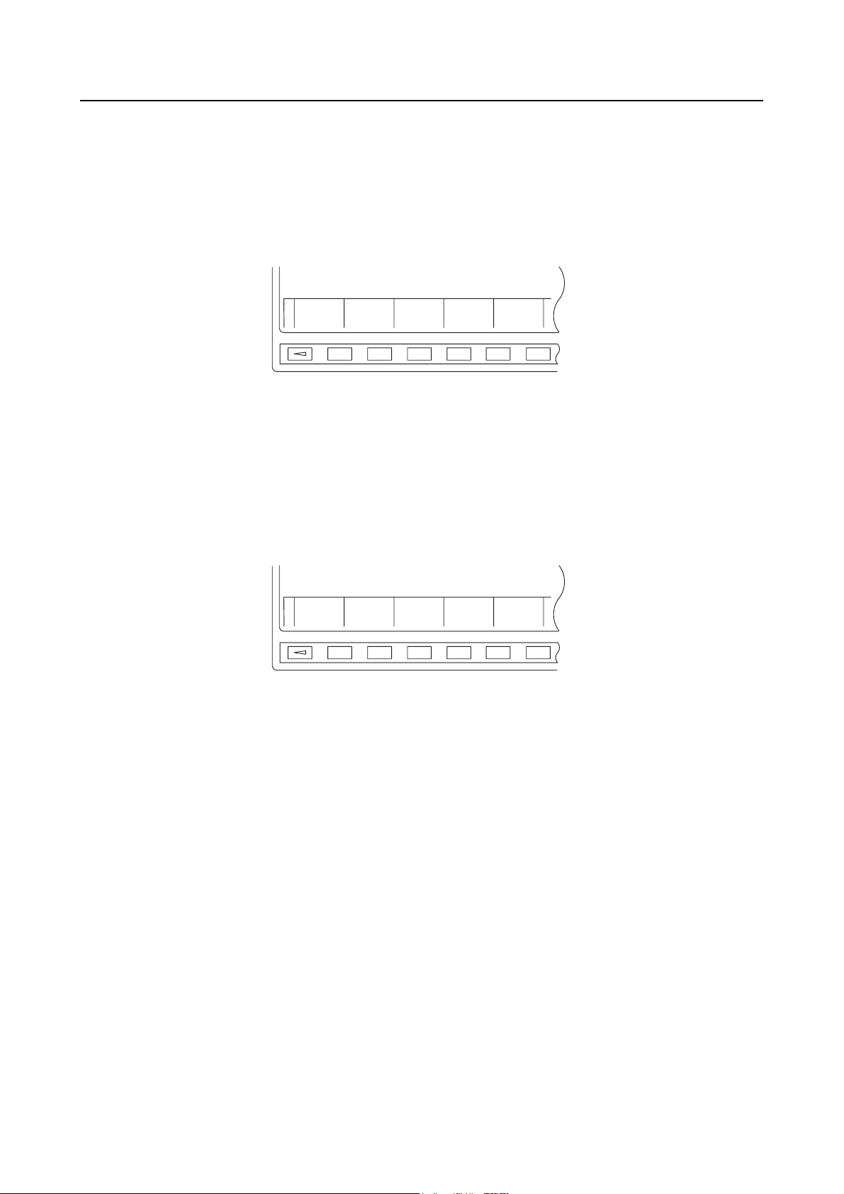
2-1-3 MANUAL OPERATION Screens
For the carrier pallet pool systems, traversal and longitudinal configurations are available.
<Traversal configuration (NH5000/NH5000 DCG)>
APPENDIX-11
[MANUAL OPERATION]
1 FORK FORWARD TO + SIDE
2FORK CENTER
3 FORK FORWARD TO − SIDE
4FORK UP
5FORK DOWN
KEY IN NO.
[ EXIT ] [ NEXT ] [ ] [ SELECT ] [ EXEC. ]
Fig. 7 MANUAL OPERATION Screen (1/2)
[MANUAL OPERATION]
6 WSS 1 SHUTTER OPEN
7 WSS 1 SHUTTER CLOSE
8 WSS 2 SHUTTER OPEN
9 WSS 2 SHUTTER CLOSE
PAGE 1/2
PAGE 2/2
KEY IN NO.
[ EXIT ] [ PREV ] [ ] [ SELECT ] [ EXEC. ]
Fig. 8 MANUAL OPERATION Screen (2/2)

APPENDIX-12
<Traversal configuration (NH4000 DCG)/Longitudinal configuration (NH5000/NH5000 DCG)>
[MANUAL OPERATION]
1 FORK FORWARD TO + SIDE
2FORK CENTER
3 FORK FORWARD TO − SIDE
4FORK UP
5FORK DOWN
6 A.G.V. CW
7 A.G.V. CCW
KEY IN NO.
[ EXIT ] [ NEXT ] [ ] [ SELECT ] [ EXEC. ]
Fig. 9 MANUAL OPERATION Screen (1/2)
[MANUAL OPERATION]
8 WSS 1 SHUTTER OPEN
9 WSS 1 SHUTTER CLOSE
10 WSS 2 SHUTTER OPEN
11 WSS 2 SHUTTER CLOSE
PAGE 1/2
PAGE 2/2
KEY IN NO.
[ EXIT ] [ PREV ] [ ] [ SELECT ] [ EXEC. ]
Fig. 10 MANUAL OPERATION Screen (2/2)
After inputting a number using the data entry, heading the required operation, press the
(INPUT) key or the [SELECT] soft-key, and the number of the selected item begins blinking with
the following message displayed on the screen.
"THEN PRESS [EXEC.] SOFT KEY"
Press the [EXEC.] soft-key, and the selected operation is executed.
Page APPENDIX-17 (APPENDIX 2-2)

When the status is established, the characters of the selected operation item are highlighted.
Pressing the [EXIT] soft-key returns the screen to the MANUAL OPERATION menu screen
(Fig. 6).
"3 FORK FORWARD TO − SIDE" is not used with NH4000 DCG.
NOTE
Note that the guidance display for 6 and 7 shows "6 CW" and "7 CCW", respectively.
2-1-4 A.G.V. INDEX Screen
[A.G.V. INDEX]
INDEX STATION NO. 31
APPENDIX-13
KEY IN NO.
[ EXIT ] [ ] [ ] [ SET ] [ EXEC. ]
Fig. 11 A.G.V. INDEX Screen
After inputting the station number of the station where the A.G.V. should be moved using the data
entry key, press the (INPUT) key or the [SET] soft-key, and the following message is
displayed on the screen.
"THEN PRESS [EXEC.] SOFT KEY"
Press the [EXEC.] soft-key, and the A.G.V. moves to the specified station.
Page APPENDIX-20 (APPENDIX 2-3)
Pressing the [EXIT] soft-key returns the screen to the MANUAL OPERATION menu screen
(Fig. 6).

APPENDIX-14
2-1-5 MAINTENANCE DOOR Screen
[MAINTENANCE DOOR]
1 MAINTENANCE DOOR LOCK
2 MAINTENANCE DOOR UNLOCK
KEY IN NO.
[ EXIT ] [ ] [ ] [ SET ] [ EXEC. ]
Fig. 12 MAINTENANCE DOOR Screen
After inputting a number using the data entry key, heading the required operation, press the
(INPUT) key or the [EXEC.] soft-key, and the number of the selected item begins blinking with the
following message displayed on the screen.
"THEN PRESS [EXEC.] SOFT KEY"
Press the [EXEC.] soft-key, and the selected operation is executed.
Page APPENDIX-21 (APPENDIX 2-4)
When the status is established, the characters of the selected operation item are highlighted.
Pressing the [EXIT] soft-key returns the screen to the MANUAL OPERATION menu screen
(Fig. 6).
This screen is not displayed for NH4000 DCG or NH5000 or NH5000 DCG.
NOTE

2-1-6 ZERO RETURN Screen
[ZERO RETURN OP.]
1 A.G.V. ZERO RETURN
2 FORK FOR./BACK ZERO RETURN
3 A.G.V. + DIRECTION FEED
4 A.G.V. − DIRECTION FEED
5 FORK FOR./BACK + FEED
6 FORK FOR./BACK − FEED
[MACHINE] A.G.V. (X) 77777.777
FORK F/B (Z) 33333.333
KEY IN NO.
[ EXIT ] [ ] [ ] [ SET ] [ EXEC. ]
APPENDIX-15
Fig. 13 ZERO RETURN OP. Screen
After inputting a number using the data entry key, heading the required operation, press the
(INPUT) key or the [SET] soft-key, and the number of the selected item begins blinking with the
following message displayed on the screen.
"THEN PRESS [EXEC.] SOFT KEY"
Press the [EXEC.] soft-key, and the selected operation is executed.
Press the function selection key (M-OPE/MDI) and select the M-OPE mode (the indicator
[M-OPE] lights).
Press the axis feed key that corresponds to the axis to be moved while holding down the
(SHIFT) key.
: The A.G.V. moves in the positive direction.
: The A.G.V. moves in the negative direction.
: The fork moves in the positive direction.
: The fork moves in the negative direction.
After completing the axis movement, press the function selection key (M-OPE/MDI) to set the
operation mode back to the MDI mode (the indicator [MDI] lights).
When the status is established, the characters of the selected operation item are highlighted.
Pressing the [EXIT] soft-key returns the screen to the MANUAL OPERATION menu screen
(Fig. 6).

APPENDIX-16
2-1-7 STATUS DISPLAY Screen
[STATUS DISPLAY]
A.G.V. ZERO POINT MEMORY
FORK ZERO RET.
ESTABLISH A.G.V. INDEX FIN.
WSS1 AUTO COUPLER CLAMP FIN.
[ EXIT ] [ ] [ ] [ ] [ ]
Fig. 14 STATUS DISPLAY Screen
When the status is established, the characters of the selected operation item are highlighted.
Pressing the [EXIT] soft-key returns the screen to the MANUAL OPERATION menu screen
(Fig. 6).
"AUTO COUPLER CLAMP FIN." item is displayed only for the auto-coupler specification
NOTE
setup station.

2-2 Pallet Pool Operation Using MANUAL OPERATION Screens
Manual pallet pool operation using the MANUAL OPERATION screens is allowed in the state
indicated below.
• The MANUAL OPERATION indicator is lit with the MANUAL/AUTO selection switch on the
operation panel set in the MANUAL position.
The following conditions must be satisfied for operating the pallet pool manually using the
MANUAL OPERATION screen.
• Not during APC cycle or pallet pool indexing cycle
• The maintenance door is closed and locked.
• The setup station shutter is closed or the setup station door is closed and locked.
• The APC rotating door of the machine is in the home position.
• The pallet pool is in the ready state.
• There are no errors occurring with the pallet pool.
APPENDIX-17

APPENDIX-18
<Station numbers>
• Standby station:
Station No. 11
• In-machine station:
Station No. 12
• Setup station:
No. 1
Machine
No. 1
Machine
1st Station
Station No. 1
• Stocker:
Stocker 1 Stocker 2 Stocker 3 Stocker 4 Stocker X
Station No. 31 32 33 34 30 + X
Standby station
34
A.G.V.
35
33
32
01
31
11
In-machine station
12
Machine
Setup station

2-2-1 FORK CENTER Operation
Press the (INPUT) key or the [SET] soft-key after inputting the code number heading the
"FORK CENTER" item using the data entry key, and the following message is displayed.
"THEN PRESS [EXEC.] SOFT KEY"
Press the [EXEC.] soft-key, and the fork moves to the central position.
The conditions required for the fork movement to the central position are indicated below.
• The fork is at the upper or lower end level position of a loading/unloading station.
• Zero return has completed with the A.G.V. and fork forward/backward operation.
2-2-2 FORK FORWARD Operation
Press the (INPUT) key or the [SET] soft-key after inputting the code number heading the
"FORK FORWARD" item using the data entry key, and the following message is displayed.
"THEN PRESS [EXEC.] SOFT KEY"
APPENDIX-19
Press the [EXEC.] soft-key, and the fork moves to the forward end position.
The conditions required for the fork movement to the forward position are indicated below.
• The fork is at the upper or lower end level position of a loading/unloading station.
• Zero return has completed with the A.G.V. and fork forward/backward operation.
2-2-3 FORK UP/FORK DOWN Operation
Press the (INPUT) key or the [SET] soft-key after inputting the code number heading the
required fork up/down level number using the data entry key, and the following message is
displayed.
"THEN PRESS [EXEC.] SOFT KEY"
Press the [EXEC.] soft-key, and the fork moves up or down to the required level.
The condition required for the fork up/down operation is indicated below.
• The fork is at the forward or backward end position (either machine side or opposite to the
machine side).
2-2-4 SHUTTER OPEN/SHUTTER CLOSE Operation
Press the (INPUT) key or the [SET] soft-key after inputting the code number heading the
required shutter operation (open or close) using the data entry key, and the following message is
displayed.
"THEN PRESS [EXEC.] SOFT KEY"
Press the [EXEC.] soft-key, and the shutter opens or closes according the selected operation.
The condition required for the fork up/down operation is indicated below.
• The fork is at the backward end position.

APPENDIX-20
2-3 A.G.V. Indexing Using A.G.V. INDEX Screen
It is possible to move the A.G.V. to the position in front of the station of the specified number.
At the A.G.V. INDEX screen, press the (INPUT) key or the [SET] soft-key after inputting the
station number of the station where the A.G.V. should move using the data entry key, and the
following message is displayed.
"THEN PRESS [EXEC.] SOFT KEY"
Press the [EXEC.] soft-key, and the A.G.V. moves to the position in front of the station of the
specified number.
Manual A.G.V. operation using the A.G.V. INDEX screen is allowed in the state indicated below.
• The MANUAL OPERATION indicator is lit with the MANUAL/AUTO selection switch on the
operation panel set in the MANUAL position.
The following conditions must be satisfied for operating the pallet pool manually using the A.G.V.
INDEX screen.
• Not during APC cycle or pallet pool indexing cycle
• The maintenance door is closed and locked.
• The setup station shutter is closed or the setup station door is closed and locked.
• The APC rotating door of the machine is in the home position.
• The pallet pool is in the ready state.
• There are no errors occurring with the pallet pool.
• The fork is at the central position.

2-4 Maintenance Door Locking/Unlocking Operation
To lock or unlock the maintenance door, the following conditions must be satisfied.
• Not during APC cycle or pallet pool indexing cycle
• There are no errors occurring with the pallet pool.
• The pallet pool is in the ready state.
2-4-1 MAINTENANCE DOOR LOCK Operation
Press the (INPUT) key or the [SET] soft-key after inputting the code number heading the
"MAINTENANCE DOOR LOCK" item using the data entry key, and the following message is
displayed.
"THEN PRESS [EXEC.] SOFT KEY"
Press the [EXEC.] soft-key, and the maintenance door is locked.
2-4-2 MAINTENANCE DOOR UNLOCK Operation
APPENDIX-21
Press the (INPUT) key or the [SET] soft-key after inputting the code number heading the
"MAINTENANCE DOOR UNLOCK" item using the data entry key, and the following message is
displayed.
"THEN PRESS [EXEC.] SOFT KEY"
Press the [EXEC.] soft-key, and the maintenance door is unlocked.
When the maintenance door is unlocked, power supply is shut off for the A.G.V. drive
NOTE
motor, the fork operating motors, and the motor driving the APC of the machine.

APPENDIX-22
2-5 Zero Return Operation
Zero return operation using the ZERO RETURN OP. screen is not allowed unless the manual
operation interlock is released.
For the procedure to release manual operation interlock, refer to page APPENDIX-26
(APPENDIX 2-6).
CAUTION
For operations which are executed on the ZERO RETURN OP. screen, interlock is not
valid or only a minimum requisite interlock is valid. Accordingly, the operations using
the ZERO RETURN OP. screen requires your special attention to ensure safe
operation.
When zero return operation is executed in the state the zero return position has been established,
the A.G.V. and the fork return to the respective zero point at a rapid feedrate.
If zero return operation is performed when the zero return position has not been established, the
operation establishes the zero point.
To change the zero return point which has already been established, set "0" for parameter 1815,
bit 4 before executing the zero return operation.
Before executing the zero return operation, it is necessary to move an axis (A.G.V. or fork) either in
rapid feedrate or jog feedrate and switch off the power supply to the NC once. This operation is
required so that the NC reads one grid of a motor. If this step is skipped, an alarm (code 90)
occurs. If alarm 90 occurs even if zero return is executed after this step, set a larger value for
parameter 1425 (FL speed for zero return operation).
2-5-1 A.G.V. ZERO RETURN Operation
1) Press the (INPUT) key or the [SET] soft-key after inputting the code number heading
the "A.G.V. ZERO RETURN" item using the data entry key, and the following message is
displayed.
"THEN PRESS [EXEC.] SOFT KEY"
2) Press the [EXEC.] soft-key.
3) Press the function selection key (M-OPE/MDI) and select the M-OPE mode (the
indicator [M-OPE] lights).
4) Press the axis feed key while holding down the (SHIFT) key.
The A.G.V. moves toward the zero position (in the positive direction).
5) After completing the axis movement, press the function selection key (M-OPE/MDI) to
set the operation mode back to the MDI mode (the indicator [MDI] lights).
The condition required for the A.G.V. zero return operation is indicated below.
• The fork is at the central position.
CAUTION
When you perform unmanned operation with the carrier pallet pool system of
longitudinal configuration, make sure that the fork position is located at 0° or 180°
position (with the fork facing toward the setup station or the pallet stocker) before
starting. If the fork is started from the 90° position, it will collide with the 90° positioning
unit somewhere between the normal traveling position to the travel zero point.

2-5-2 FORK FOR./BACK ZERO RETURN Operation
1) Press the (INPUT) key or the [SET] soft-key after inputting the code number heading
the "FORK FOR./BACK ZERO RETURN" item using the data entry key, and the following
message is displayed.
"THEN PRESS [EXEC.] SOFT KEY"
2) Press the [EXEC.] soft-key.
3) Press the function selection key (M-OPE/MDI) and select the M-OPE mode ((the
indicator [M-OPE] lights).
4) Press the axis feed key while holding down the (SHIFT) key.
The fork moves toward the zero position (in the positive direction).
5) After completing the axis movement, press the function selection key (M-OPE/MDI) to
set the operation mode back to the MDI mode (the indicator [MDI] lights).
APPENDIX-23
To execute zero return in the state the zero point has not been established, move the fork
manually forward to the machine side before executing zero return; the zero point of the fork in the
forward/backward direction is near the center of the forward/backward stroke. If zero return is
executed with the fork positioned near the center or at a position opposite to the machine side, the
fork moves backward to the end position opposite to the machine side and zero return operation
cannot be executed.
2-5-3 A.G.V. + DIRECTION FEED Operation
1) Press the (INPUT) key or the [SET] soft-key after inputting the code number heading
the "A.G.V. + DIRECTION FEED" item using the data entry key, and the following message
is displayed.
"THEN PRESS [EXEC.] SOFT KEY"
2) Press the [EXEC.] soft-key.
3) Press the function selection key (M-OPE/MDI) and select the M-OPE mode (the
indicator [M-OPE] lights).
4) Press the axis feed key while holding down the (SHIFT) key.
The A.G.V. moves in the positive direction.
5) After completing the axis movement, press the function selection key (M-OPE/MDI) to
set the operation mode back to the MDI mode (the indicator [MDI] lights).
The A.G.V. does not move unless the fork is at the central position.
NOTE

APPENDIX-24
2-5-4 A.G.V. − DIRECTION FEED Operation
1) Press the (INPUT) key or the [SET] soft-key after inputting the code number heading
the "A.G.V. − DIRECTION FEED" item using the data entry key, and the following message
is displayed.
"THEN PRESS [EXEC.] SOFT KEY"
2) Press the [EXEC.] soft-key.
3) Press the function selection key (M-OPE/MDI) and select the M-OPE mode (the
indicator [M-OPE] lights).
4) Press the axis feed key while holding down the (SHIFT) key.
The A.G.V. moves in the negative direction.
5) After completing the axis movement, press the function selection key (M-OPE/MDI) to
set the operation mode back to the MDI mode (the indicator [MDI] lights).
The A.G.V. does not move unless the fork is at the central position.
NOTE
2-5-5 FORK FOR./BACK + FEED Operation
1) Press the (INPUT) key or the [SET] soft-key after inputting the code number heading
the "FORK FOR./BACK + FEED" item using the data entry key, and the following message
is displayed.
"THEN PRESS [EXEC.] SOFT KEY"
2) Press the [EXEC.] soft-key.
3) Press the function selection key (M-OPE/MDI) and select the M-OPE mode (the
indicator [M-OPE] lights).
4) Press the axis feed key while holding down the (SHIFT) key.
The fork moves in the positive direction.
5) After completing the axis movement, press the function selection key (M-OPE/MDI) to
set the operation mode back to the MDI mode (the indicator [MDI] lights).

2-5-6 FORK FOR./BACK − FEED Operation
1) Press the (INPUT) key or the [SET] soft-key after inputting the code number heading
the "FORK FOR./BACK − FEED" item using the data entry key, and the following message is
displayed.
"THEN PRESS [EXEC.] SOFT KEY"
2) Press the [EXEC.] soft-key.
3) Press the function selection key (M-OPE/MDI) and select the M-OPE mode (the
indicator [M-OPE] lights).
4) Press the axis feed key while holding down the (SHIFT) key.
The fork moves in the negative direction.
5) After completing the axis movement, press the function selection key (M-OPE/MDI) to
set the operation mode back to the MDI mode (the indicator [MDI] lights).
APPENDIX-25

APPENDIX-26
2-6 Releasing Manual Operation Interlock
The following message is displayed when the (INPUT) key is pressed after inputting "98" at
the PCMDI MENU screen using the data entry key:
"RELEASE MN INTERLOCK? (YES/NO)"
To release the manual operation interlock, press the [YES] soft-key.
The manual operation interlock release state is cleared once you exit the screen.
CAUTION
In the state the manual operation interlock is released, interlock is not valid or only a
minimum requisite interlock is valid. Accordingly, operations to be executed in such a
state requires your special attention to ensure safe operation.

APPENDIX 3 MAINTENANCE OPERATION
3-1 Adjustment at Start-up
The following describes the procedure to be followed when starting up the pallet pool or extending
the pallet pool capacity.
1) Set the number of stockers, machines, and setup stations.
↓
2) Execute zero return of the A.G.V. and fork.
(This step may be skipped if the zero return position has already been established.)
↓
3) Enter the position data of the A.G.V. and the fork corresponding to stockers, machines, and
setup stations.
↓
4) Check the correctness of the data by manually moving the A.G.V. and the fork.
APPENDIX-27
↓
Completion

APPENDIX-28
1) Setting the number of stockers, machines, and setup stations
Press the function selection key (SETTING) on the operation panel, and then press the
SETTING
[CUSTOM] soft-key to display the PCMDI MENU screen.
Key in "97" at the PCMDI MENU screen and press the (INPUT) key. Then, the screen
shown below will be displayed. Set the number of stockers, machines, and setup stations
meeting the actual configuration.
To change the values already set and displayed on the screen, password "76543210" must
be input at the PCMDI MENU screen.
[BYTE DATA SETTING]
NUMBER OF STOCKER 10
NUMBER OF MACHINE 1
NUMBER OF WSS 2
[ EXIT ] [ ] [ ] [ ] [ SET ]
Fig. 15 BYTE DATA SETTING Screen
2) Executing zero return of the A.G.V. and fork
Execute zero return of the A.G.V. and the fork according to the procedure explained in
APPENDIX 2-5 "Zero Return Operation".
3) Enter the position data of the A.G.V. and the fork corresponding to stockers, machines, and
setup stations according to the procedure explained in APPENDIX 1-4 "Registering Position
Data of the A.G.V. and the Fork".
4) Checking the correctness of the data by manually moving the A.G.V. and the fork
Check the correctness of the entered data by actually moving the A.G.V. and the fork
according to the procedure explained in APPENDIX 2 "OPERATION USING MANUAL
OPERATION SCREENS".

APPENDIX-29
APPENDIX 4 OPERATION OF AUTO-COUPLER (OPTION)
<Specifications>
Installation of an auto-coupler simplifies clamping of a fixture in setting up steps.
For clamping/unclamping a fixture, a footswitch is installed at setup stations. The footswitch
toggles - stepping on the footswitch while the fixture is clamped causes the fixture to be
unclamped and stepping on the footswitch while the fixture is unclamped causes the fixture to be
clamped.
<Conditions>
To clamp or unclamp the fixture, all of the conditions indicated below must be satisfied.
• The setup station door is closed.
• The MRDY indicator is lit.
• The SET FIN or NO SET indicator is not lit.
The FIXTURE CLAMP indicator is lit when the following conditions are satisfied.
• The fixture is clamped.
• The workpiece correct holding signal is on (only when the correct holding check switch is
used).
Conditions required to unload a pallet from the setup station are indicated below.
• To transport a pallet after setting up a workpiece on it, the fixture must be clamped with the
workpiece correct holding signal ON. Unless these conditions are satisfied, the SET FIN
indicator in the SET FIN button does not light even if the button is pressed and thus the
transport of a pallet does not start.
• To transport a pallet without setting up a workpiece on it, the fixture must be clamped.
Unless the fixture is clamped, the NO SET indicator in the NO SET button does not light
even if the button is pressed and thus the transport of a pallet does not start. In this case,
the status of the workpiece correct holding signal is disregarded.

APPENDIX-30
APPENDIX 5 PC-BASED (MCC-LPS) CONTROL (OPTION)
PC-based (MCC-LPS) control of the linear pallet pool system is possible. PC-based control
enables the use of flexible functions tailored to actual conditions: for example you can reliably
ascertain the system operating status and machining record using simple operations, and deal
with interruption processing of urgent workpieces.
5-1 Schematic Diagram of Pallet Pool System
Machine
In machine
Machine side
APC rotary door
Buffer station
12
NOTE
A.G.V.
31 33 35 36 37 38 1
Fork
Opposite to the machine side
Fig. 16 Schematic Diagram of Pallet Pool System (Carrier Pallet Pool)
Shutter
Setup station operation panel
113432
Setup station
Control panel
1. Actual arrangement of the equipment varies according to the pallet pool system
configuration.
2. The numbers given in the diagram above indicate the station numbers.

5-2 Station Numbers
Max. number of stations and machines
• Machines . . . . . . . . . 2
• Setup stations . . . . . 2
• Stocker. . . . . . . . . . . 30
• Buffer station (for 2 machines):
APPENDIX-31
No. 1
machine
Station No. 11 14
• In-machine station (for 2 machines):
No. 1
machine
Station No. 12 15
• Setup station (for 2 setup stations):
1st station 2nd station
Station No. 1 2
• Stocker:
Stocker 1 Stocker 2 Stocker 3 Stocker 4 Stocker X
No. 2
machine
No. 2
machine
Station No. 31 32 33 34 30 + X

APPENDIX-32
5-3 Data Table Numbers
The data table numbers of the data table where the fork position data corresponding to the
individual stations is entered are described in Table 2.
Table 2 Power Mate iH Control
Station
No.
Station Name
X Coordinate
(Traveling axis)
Address
Z Coordinate
(Fork axis)
Address
A.G.V. Rotation
Direction
Address
1 Setup station 1 D204 D604 D1101
2 Setup station 2 D208 D608 D1102
11 Machine station 1 front D244 D644 D1111
14 Machine station 2 front D256 D656 D1114
31 Stocker 1 D324 D724 D1131
32 Stocker 2 D328 D728 D1132
33
30 + a
60
Stocker 3
Stocker a
Stocker 100
"A.G.V. Rotation Direction" is used for the turn type A.G.V. specification.
NOTE
D332
D(320 + a × 4)
D440
D732
D(720 + a × 4)
D840
D(1130 + a)
Set "1" for turning the A.G.V. CW, and "0" for turning the A.G.V. CCW for each station.
D1133
D1160
5-4 Parameters
Table 3 Related Parameters
Correspondence with MCC-LPS
Parameter No. Description
D101.4
D106.4
For both:
1: PMC control
0: MCC-LPS

Comment Form
To improve this manual, we invite you to make comments on any insufficient description or errors in this
manual. We want to know how you think we can make this manual better. Please restrict your comments to
those concerning this manual only. Comments can also be submitted using the company website at
http://www.moriseiki.com.
Name of Manual INSTRUCTION MANUAL
Number of Revisions PPM-NHCPP-C1EN (2007.1)
Name Company
Department Telephone
Address
Chapter Page Line Comments/Requests
Date:
For Mori Seiki's Use - Do not write below this line.
Description Reception No. Received by

http://www.moriseiki.com
MORI SEIKI CO., LTD.
Nagoya Head Office
Nara Campus
Iga Campus
Chiba Campus
2-35-16 Meieki, Nakamura-ku, Nagoya City, Aichi 450-0002, Japan
Phone: (052) 587-1811 Fax.: (052) 587-1818
362 Idono-cho, Yamato-Koriyama City, Nara 639-1183, Japan
Phone: (0743) 53-1121
106 Kita Koriyama-cho, Yamato-Koriyama City, Nara 639-1160, Japan
Phone: (0743) 53-1125
201 Midai, Iga City, Mie 519-1414, Japan
Phone: (0595) 45-4151
488-19 Suzumi-cho, Funabashi City, Chiba 274-0052, Japan
Phone: (047) 410-8800
MORI SEIKI U.S.A., INC.
Head Office
Administrative Department
Technical Centers
Representative Office
5655 Meadowbrook Drive, Rolling Meadows, Illinois 60008
Phone: (1)-847-593-5400 Fax.: (1)-847-593-5433
2100 Golf Road Suite 300, Rolling Meadows, Illinois 60008
Phone: (1)-847-290-8535 Fax.: (1)-847-290-5500
Chicago, Dallas, Los Angeles, Detroit, Cincinnati, Boston, New Jersey
Charlotte, San Francisco
MORI SEIKI MEXICO, S.A. DE C.V.
Head Office & Technical Center
Montecito 38 Piso 12-38 Col. Napoles 03810 México D.F.
Phone: (52)-55-9000-3276 Fax.: (52)- 55-9000-3279
MORI SEIKI BRASIL LTDA.
Head Office & Technical Center
Rua República do Iraque, 1432 2 and, Campo Belo 04611-002 São Paulo - SP, Brasil
Phone: (55)-11-5543-1762 Fax.: (55)-11-5543-1948
MORI SEIKI ESPAÑA S.A.
Head Office & Technical Center
Calle de la Electrónica, Bloque B, Nave 9 Poligono Industrial "La Ferreria" 08110
Montcada I Reixac (Barcelona), Spain
Phone: (34)-935-75-36-46 Fax.: (34)-935-75-08-47
MORI SEIKI SINGAPORE PTE LTD
Head Office & Technical Center
Technical Center
3 Toh Guan Road East, Singapore 608835
Phone: (65)-6560-5011 Fax.: (65)-6567-6234
MALAYSIA BRANCH
MORI SEIKI (THAILAND) CO., LTD.
Head Office & Technical Center
119/2 Moo 8, Bangnathani Building 1st Floor A1, Bangna-Trad KM.3 Road Kwaeng
Bangna, Khet Bangna, Bangkok 10260, Thailand
Phone: (66)-2-361-3700-5 Fax.: (66)-2-361-3706
MORI SEIKI (TAIWAN) CO., LTD.
Head Office & Technical Center
No. 8, Kong 8th Road, Linkou No. 2 Industrial District, Linkou Hsiang, Taipei Hsien,
Taiwan, R.O.C.
Phone: (886)-2-2603-1701 Fax.: (886)-2-2603-1706
MORI SEIKI HONG KONG LIMITED
Head Office & Technical Center
Unit 02, 8/F., Vicwood Plaza, 199 Des Voeux Road, Central, Hong Kong
Phone: (852)-2757-8910 Fax.: (852)-2757-7839
MORI SEIKI (SHANGHAI) CO., LTD.
Head Office
Technical Center
Room 4301, 4307, Maxdo Center, No.8 Xing Yi Rd., HongQiao Development Zone,
Shanghai 200336, China
Phone: (86)-21-5208-0270 Fax.: (86)-21-5208-0273
Shanghai, Beijing, Tianjin, Dalian, Shenzhen, Chongqing, Guangzhou
MORI SEIKI GmbH
Head Office
Technical Centers
Antoniusstrasse 14, 73249 Wernau, Germany
Phone: (49)-7153-934-0 Fax.: (49)-7153-934-220
Stuttgart, Istanbul, Prague, München, Hamburg, Düsseldorf
MORI SEIKI (UK) LTD.
Head Office
Technical Centers
Representative Office
202 Bedford Avenue, Slough SL1 4RY, England
Phone: (44)-1753 526518 Fax.: (44)-1753 524695
London, Birmingham
Leicester
MORI SEIKI FRANCE S.A.S.
Head Office & Technical Center
Technical Centers
Parc du Moulin, 1 Rue du Noyer BP 19326 Roissy en France 95705 Roissy CDG
Cedex, France
Phone: (33)-1-39-94-68-00 Fax.: (33)-1-39-94-68-59
Toulouse, MS SYFRAMO S.A.S.
MORI SEIKI ITALIANA S.R.L.
Head Office & Technical Center
Via Riccardo Lombardi N. 10, 20153 Milano, Italy
Phone: (39)-02-4894921 Fax.: (39)-02-48914448
MORI SEIKI KOREA CO., LTD.
Head Office & Technical Center
A-101, 2 SK TWIN TECH TOWER, 345-9 Kasan-dong, Kumcheon-Ku, Seoul,
Korea
Phone: (82)-2-862-0925 Fax.: (82)-2-862-0928
PT. MORI SEIKI INDONESIA
Head Office & Technical Center
Komplek Gading Bukit Indah Blok M/01 J1. Bukit Gading Raya, Kalapa Gading,
Jakarta Utara, 14240 Indonesia
Phone: (62)-21-453-1199 Fax.: (62)-21-4585-7414
MORI SEIKI CO., LTD. India Branch
Head Office & Technical Center
India Branch: 404 A World Trade Centre, Babar Rd. Connaught Place,
Phone: (91)-11-4152-8520 Fax.: (91)-11-4152-8530
New Delhi - 110001, India
MORI SEIKI AUSTRALIA PTY LTD
Head Office
Technical Centers
6/6 Garden Road Clayton VIC 3168, Australia
Phone: (61)-3-8545-0900 Fax.: (61)-3-9561-4999
Melbourne, Sydney
The export of this product is subject to an authorization from the government of the exporting country.
Check with the government agency for authorization.
Printed in Japan
061110
 Loading...