

Page 1

Page 2
II
III
1
11
12
13
13
14
16
17
19
20
21
23
24
26
27
27
28
29
30
32
39
43
44
44
46
50
51
54
55
59
60
60
62
63
65
67
69
71
I
Page 3

Figure 1: Front View (Calisto 2 model shown) ................................................................................................................................... 6
Figure 2: Calisto/Calisto 2 - Bottom View .......................................................................................................................................... 6
Figure 3: Calisto/Calisto 2 - Main Internal Components ................................................................................................................. 7
Figure 4 : Calisto/Calisto 2 - Mounting Diagram............................................................................................................................. 12
Figure 5: Calisto/Calisto 2 - Interface Board Components ........................................................................................................... 15
Figure 6: Calisto/Calisto 2 - Power Connections ............................................................................................................................. 16
Figure 7: Calisto/Calisto 2 - Alarm Relays and Connections ......................................................................................................... 17
Figure 8: Calisto/Calisto 2 - Analog Output Connector ................................................................................................................. 19
Figure 9: Calisto/Calisto 2 - 4-20 mA Analog Input Connector ................................................................................................... 21
Figure 10: Calisto/Calisto 2 - RS-485 Connection ........................................................................................................................... 22
Figure 11: Calisto/Calisto 2 - RS-232 Connection ........................................................................................................................... 24
Figure 12: Calisto/Calisto 2 - RJ45 Ethernet port ........................................................................................................................... 25
Figure 13: Ethernet Outdoor Connectivity Kit Patchcord ............................................................................................................. 25
Figure 14: Tee Fitting Assembly for the Precision Oil Temperature Probe Option ................................................................. 29
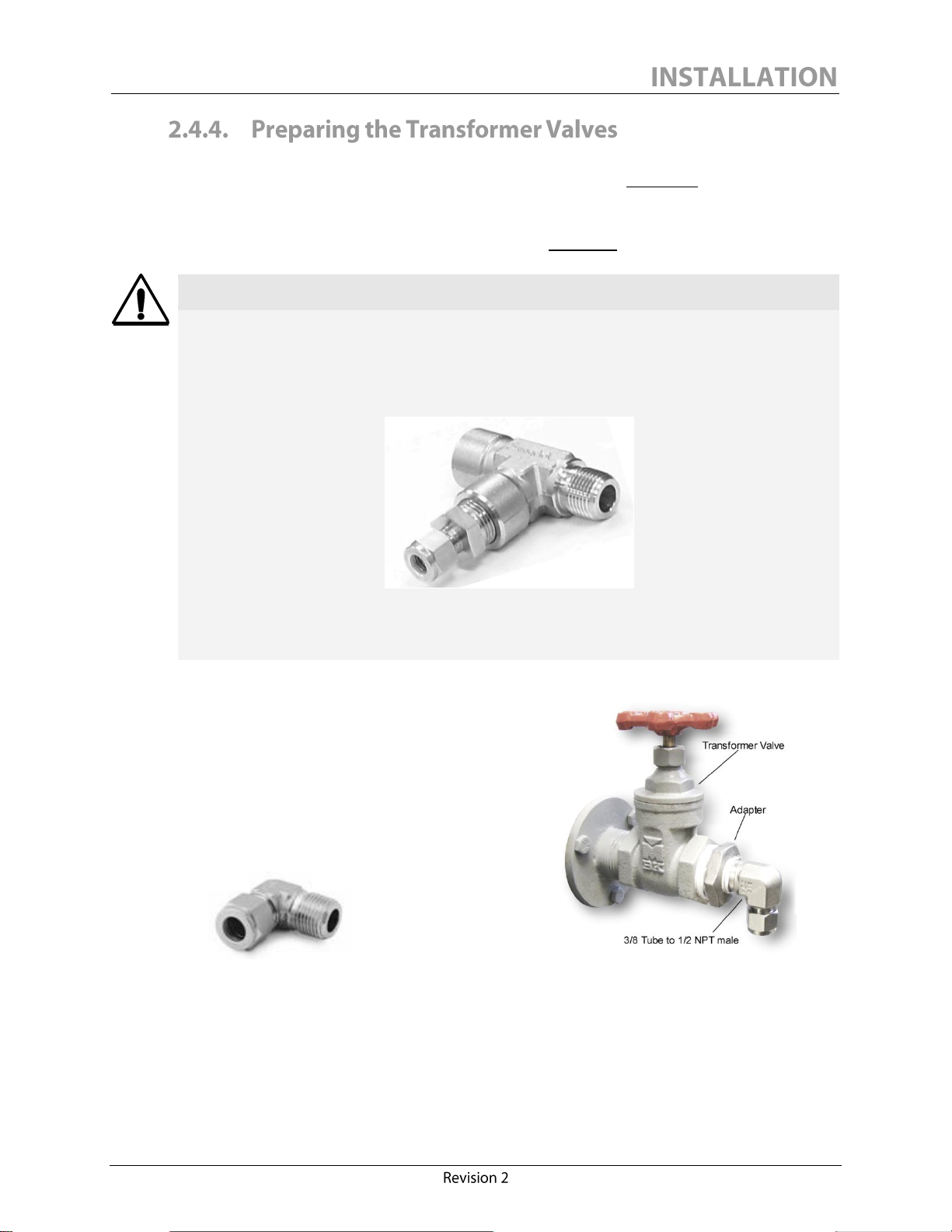
Figure 15: Transformer Valve Elbow Fitting .................................................................................................................................... 29
Figure 16: Adapting the Transformer Valve ..................................................................................................................................... 29
Figure 17: Attaching the Copper Tubing to the INLET Port ....................................................................................................... 30
Figure 18: Attaching the Copper Tubing to the OUTLET Port ................................................................................................... 31
Figure 19: Monitor with Both Valves Closed .................................................................................................................................... 32
Figure 20: Quick Connect Oil Sampling Tube ................................................................................................................................. 33
Figure 21: Connecting the Quick Connect Oil Sampling Tube to the monitor ......................................................................... 33
Figure 22: Flushing the Oil RETURN Tube ..................................................................................................................................... 34
Figure 23: Flushing the Oil SUPPLY Tube ....................................................................................................................................... 35
Figure 24: Disconnecting the Quick Connect Oil Sampling Tube from the Monitor .............................................................. 35
Figure 25: Monitor with both Valves Open ...................................................................................................................................... 36
Figure 26: Calisto/Calisto 2 Display Interface Structure ................................................................................................................ 42
Figure 27: 6-Feet Long A/B Type USB Cable.................................................................................................................................. 43
Figure 28: Calisto Access Status Tab with an Error Code .............................................................................................................. 47
Figure 29: Error Code Interpretation Chart ...................................................................................................................................... 48
Figure 30: Calisto Access Settings Tab ............................................................................................................................................... 51
Figure 31: DNP3/RS485 ...................................................................................................................................................................... 53
Figure 32: DNP3/TCP ......................................................................................................................................................................... 53
Figure 33: Calisto/Calisto 2 Access Default Set-Up ........................................................................................................................ 56
Figure 34: Oil Types Selection ............................................................................................................................................................. 61
Figure 35: Calisto Access External Input Settings ........................................................................................................................... 62
Figure 36: Calisto Access Graphic Plotting Panel– H2 ................................................................................................................... 66
Figure 37: Calisto Access Graphic Plotting Panel – CO for Calisto 2 only ................................................................................. 66
Figure 38: Calisto Access Graphic Plotting Panel – H2O .............................................................................................................. 66
Figure 39: Quick Connect Oil Sampling Tube Connected to a 30cc Syringe ............................................................................. 67
Figure 40: 30cc Syringe Connected to the Monitor SAMPLING Port ........................................................................................ 67
II
Page 4

DISCLAIMER
The Calisto/Calisto 2 IED (Intelligent Electronic Device) has been carefully designed
and engineered to provide maximum accuracy while continuously monitoring the
concentration of dissolved gases in transformer oil.
It is assumed by Morgan Schaffer that users will read this Installation & Operation Manual
and will understand the operation of the instrument prior to installation of the IED.
All results obtained using the Calisto/Calisto 2 monitor are based upon material and
equipment under the responsibility of the client. Morgan Schaffer assumes no
responsibility and makes no warranty or representation, expressed or implied, as to the
condition, productivity or proper operation of any equipment or other property for
which the Calisto/Calisto 2 monitor may be used or relied upon for any reason
whatsoever.
The Calisto/Calisto 2 monitor is designed to be permanently installed on critical transformers for
continuous measurement of dissolved fault gases in dielectric insulating fluids. Calisto and Calisto 2
monitor hydrogen and moisture. Hydrogen is a reliable indicator of a recent or existing fault, as all
fault types produce it to a greater or lesser extent.
Calisto 2 also monitors carbon monoxide. Carbon monoxide and moisture levels may highlight
undesirable deterioration of the paper/oil system, and conditions conducive to such deterioration.
Calisto 2 provides the key measurements required to monitor the health of the insulation system, in
order that informed service decisions may be taken, and major transformer problems may be
avoided.
III
Page 5

Page 6
NOTICE
This manual applies to both Calisto and Calisto 2 monitors. Always consider which one
you are working with. Some sections of this manual apply to Calisto 2 only and are
expressly marked “for Calisto 2 only”. If not stated, the section applies to both Calisto
and Calisto 2 monitors.
An electronic version of this manual is available on the Calisto/Calisto 2 CD supplied with your
monitor and at Morgan Schaffer’s web site www.morganschaffer.com. To access this manual on the
website, click Instruments under Products. Then click either Calisto or Calisto 2 and then
Downloads under the Menu (on the right). In order to use the electronic manual efficiently,
proceed as follows after opening Acrobat Reader®:
1. Click Window, Show Bookmarks.
2. Click View, Fit Width.
3. Click View, Continuous.
When necessary, use the Zoom command to view drawing or picture details.
This Installation & Operation Manual provides the required information for installing and setting up a
Calisto monitor version C76-00000 or a Calisto 2 monitor version C85-00000 for operation. All
types of signals, alarm relays and communications are also covered. Users should visit Morgan
Schaffer’s website regularly at www.morganschaffer.com or contact us directly for documentation,
firmware and software updates.
1
Page 7

A 3-year warranty covers each new Calisto/Calisto 2 IED. In order to activate this warranty, the user
must fill out the Warranty Registration Form located in the documentation included with each
instrument and fax it to Morgan Schaffer at 001.514.739.0434. An electronic version of this form is
also available on the Calisto/Calisto 2 CD and can be e-mailed to support@morganschaffer.com
once it has been filled out. Upon receiving the registration form, Morgan Schaffer will confirm the
validity period of the warranty. End users may also visit our website and electronically register their
monitor. In the main menu, under Products, click Instruments and then Calisto or Calisto 2. On
the right side of the menu, click Registration. The warranty can be activated at any time within the
6-month period following the shipping date from Morgan Schaffer. Additional information must be
provided by the end-user if registration of the warranty is performed after the activation period.
Extended warranties are available from Morgan Schaffer. Extended warranty confirmations will be
provided at the time of their purchase or when the standard Warranty Registration Form is received.
2
Page 8

Precise, accurate and continuous hydrogen readings allow detection of transformer incipient
faults at their earliest stage. Hydrogen is a reliable indicator of a recent or existing fault as all fault
types produce it to a greater or lesser extent. Hydrogen’s low solubility in oil and high diffusibility
facilitate its early detection at low concentrations thus providing the earliest warning of the presence
of a fault.
Precise, accurate and continuous moisture readings allow correlations to be established
between moisture in oil and transformer load. They also provide key information on long term
trends of the insulation conditions. In combination with polar products and acids, dissolved water
can significantly affect the dielectric properties of insulating fluids and materials. Monitoring
dissolved water over an extended period of time and undertaking proper action following sudden or
abnormal increases in dissolved water content extends the life expectancy, performance and
serviceability of oil-filled equipment.
Additional continuous measurement of dissolved carbon monoxide in oil differentiates the
Calisto 2 from the Calisto monitor. Carbon monoxide readings can help transformer specialists
assess the remaining life of transformers. Carbon monoxide is often generated in large quantities
when transformer cellulose overheats.
Built-in oil circulation and flow monitoring assure reliability of the readings. Effective on-line
monitoring of dissolved fault gases requires that sensors be in continuous contact with
representative oil from the transformer, in order to react quickly to variations in gas concentrations.
To guarantee accuracy and fast response to developing faults, Calisto/Calisto 2 features an oil
circulation system based on an anti-cavitation reciprocating pump with an outstanding reliability
record. In addition, an integrated oil flow monitor, also designed for maintenance-free operation and
long-term reliability, provides a low-flow warning if the flow drops below a pre-set threshold, as may
occur if a valve is inadvertently closed.
Continuous enclosure and oil conditioning is essential for accurate readings. The most important
source of interference on dissolved gas sensors comes from environmental temperature variations.
Varying ambient and oil temperatures significantly affect the solubility and diffusion rates of
dissolved fault gases, leading to baseline drift and signal variation. This often limits the ability of
IEDs to monitor low levels of fault gases. Calisto/Calisto 2 features passive and thermo-electric
temperature conditioning modules which continuously maintain both enclosure and oil temperatures
constant to pre-set levels. This results in unequalled sensitivity, repeatability and long-term stability,
independent of the environment where the instrument is installed.
Reliable gas extraction and detection technologies are both crucial to produce reliable readings.
As the oil within the Calisto/Calisto 2 is conditioned to a precisely regulated temperature, it is
pumped past a bundle of PTFE capillary tubes which together form the gas probe. Dissolved gases
permeate through the walls of the tubing to form a representative gas sample within the probe.
Gases then diffuse along the capillary tubes to form a gas sample inside the detection cell. Any
change in gas concentrations in the oil will modify the equilibrium within the probe and the cell.
The Calisto/Calisto 2 detection cell uses an enhanced version of Morgan Schaffer’s proprietary
high-accuracy thermal conductivity detection (TCD) technology, to provide accurate gas
3
Page 9

measurements, without any field calibration, for the lifetime of the instrument. The Calisto and
Calisto 2 detection cells take validated measurements for hydrogen and carbon monoxide (Calisto 2
only) every three hours. Validated measurements are continuously zeroed to guarantee long-term
stability and low-level detection accuracy. A continuous measurement of the hydrogen concentration
is also performed for both monitors, to indicate any variation in hydrogen concentration which may
occur between validated readings.
Vacuum tolerance is made possible because of the intrinsic properties of the capillary tubing used
to form the gas sample and because the oil circulating and conditioning systems inside the
Calisto/Calisto 2 can both sustain vacuum. As a result, no action is required to protect the monitor
if the transformer is put under vacuum for degassing purposes.
Precise moisture measurement is achieved using a capacitive thin-film sensor immersed directly
in circulating oil to continuously measure dissolved moisture. Moisture content can be reported in
parts per million (ppm), %RS at 25oC (77°F) or %RS at a specific transformer temperature using the
Expert Series Calisto Precision Oil Temperature Probe.
4
Page 10

The complete technical specifications of the two instruments are included in Appendix I of this
manual. Prior to installing or commissioning the IED, users should understand the basic principles
of operation of the instrument and identify the main components of the built-in systems. Both
Calisto and Calisto 2 monitors feature substantially the same internal components and user interface
hardware. The detection cells are calibrated differently and are specific to each monitor type.
The instrument is usually installed permanently on a transformer or a pedestal-style mounting stand.
The system requires that oil from the transformer be brought to the IED and then returned to the
transformer. To accomplish this, Calisto/Calisto 2 features separate oil inlet and outlet ports. Oil
circulation is achieved with the use of a small reciprocating pump (nominal flow of 60 ml/min. or
0.95 US gal/hr) located inside the instrument.
Figure 1 on the following page shows the general front view of a Calisto/Calisto 2 which features a
vacuum fluorescent display (ultra bright at day and night) and the three-button display interface.
Figure 2 illustrates the main features visible on the bottom view of a Calisto/Calisto 2, including the
oil inlet/outlet ports and the quick-connect oil sampling port.
Figure 3 illustrates the main components inside a Calisto/Calisto 2.
Calisto/Calisto 2 IED controls the oil temperature and the air temperature inside the enclosure
using heat exchangers and thermo-electric elements. A waterproof long-life cooling fan, located at
the bottom of the enclosure, provides the primary heat removal from the system. A small fan,
located inside the enclosure, provides temperature stability to the electronics and the gas
measurement cell.
When the system is in operation, date and time stamped measurements are stored in the
instrument’s memory at a factory set storage frequency of one reading every 3 hours. This data can
be retrieved and viewed graphically using Morgan Schaffer’s Calisto Access software. Data can also
be viewed at any time on the door display, which provides the most recent validated hydrogen and
carbon monoxide (Calisto 2 only) measurements, in addition to the real-time dissolved moisture
measurements. Other instrument operation and manufacturing parameters can be viewed on the
display. Section 3.3 describes the operation of the display buttons in detail.
5
Page 11
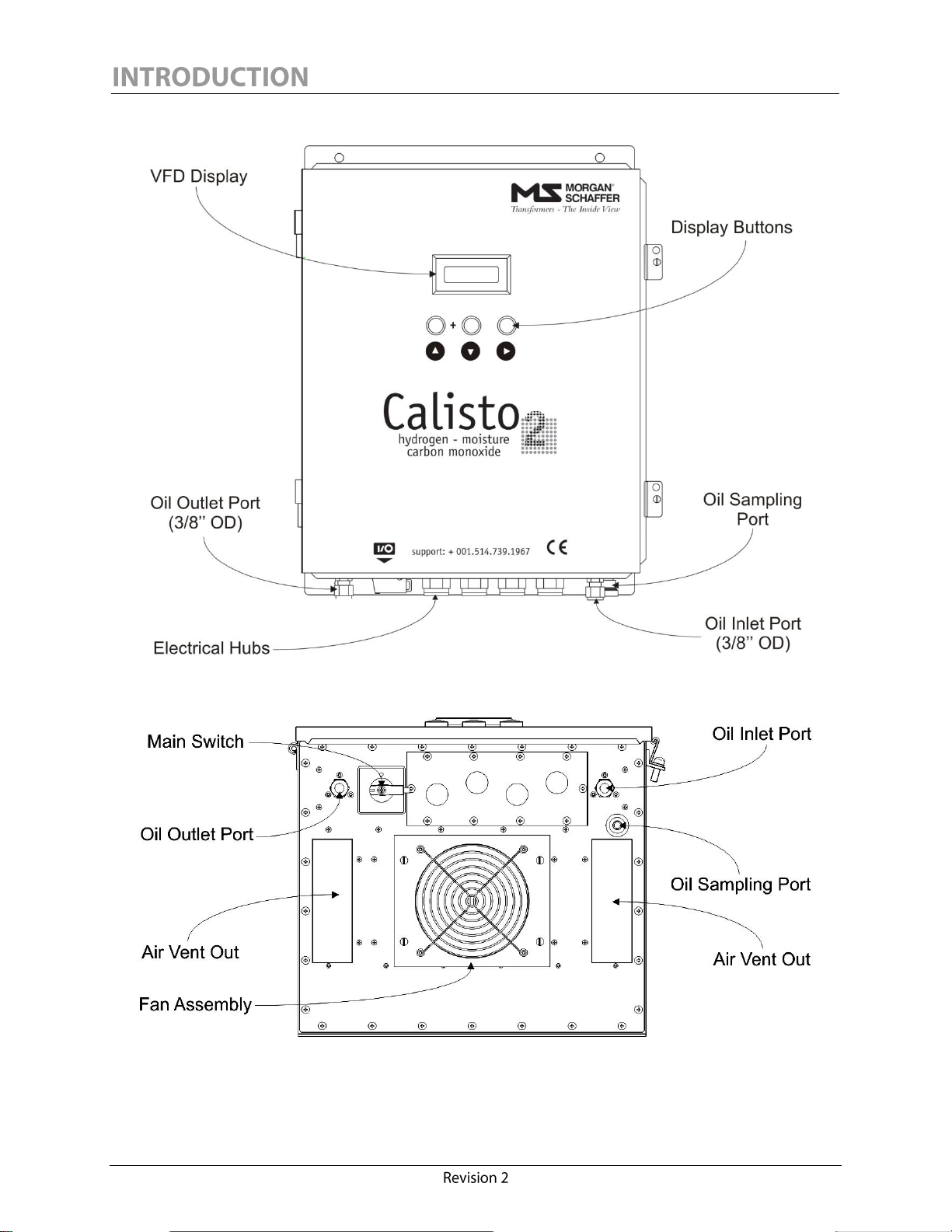
Figure 1: Front View (Calisto 2 model shown)
Figure 2: Calisto/Calisto 2 - Bottom View
6
Page 12
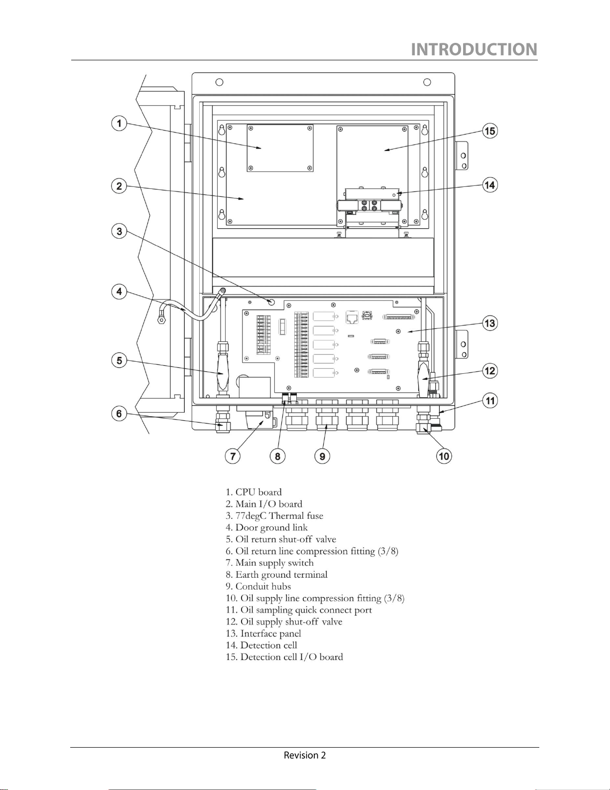
Figure 3: Calisto/Calisto 2 - Main Internal Components
7
Page 13
QTY.
DESCRIPTION
1
Standard Calisto/Calisto 2 monitor
1
6-foot male A/B USB 2.0 cable for local connection
1
Calisto Access interface software CD-ROM
1
Quick Connect Oil Sampling Tube
4
Stainless steel vibration mount assembly
2
Copper tubing – 3/8 O.D. × 25 ft (7.6 m)
1
Thermal cut-off fuse (spare)
2
Brass elbow – ½ NPT (M) – 3/8" Tube
4
Brass nut – 3/8 Tube
4
One-lokTM brass ferrule – 3/8 Tube
1
Shipping box
1
Installation & Operation Manual (softcopy, also available on our website)
1
Factory Test Certificate
1
Declaration of Conformity
8
Page 14
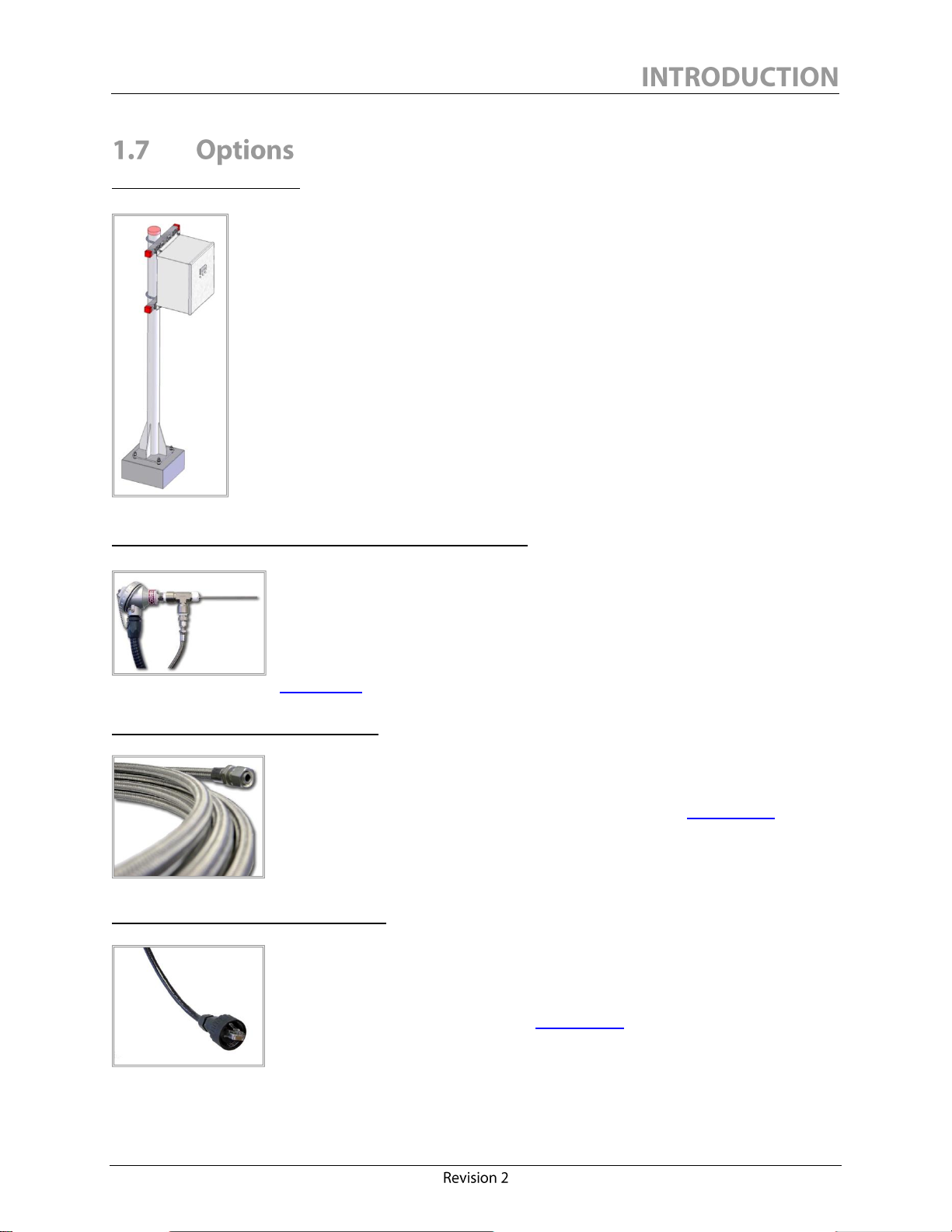
Calisto Mounting Stand
For a fast and easy installation, Morgan Schaffer has designed a pedestal-style
mounting stand for Calisto/Calisto 2. This stand is highly corrosion resistant
and includes all required hardware to perform the installation in less than one
hour.
Precision Oil Temperature Probe – Standard Edition
The Precision Oil Temperature Probe was specifically developed to meet
client demands to report the %RS in oil at a specific transformer temperature
in a truly accurate and reliable way. The 610 mm (24 in.) temperature probe is
customized at the moment of the installation of the monitor and does not
require any specifications from the client at the time of the order. Refer to
Appendix I for the complete technical specifications.
Stainless Steel Braided Flex Lines
The Stainless Steel Braided Flex Lines are a popular customizable option for
the Calisto/Calisto 2 configuration that has the advantage of being highly
resistant to corrosion and easy to install. Refer to Appendix I for the
complete technical specifications.
Ethernet Outdoor Connectivity Kit
Calisto/Calisto 2 features an Ethernet port isolated to 1500 V. The Ethernet
Outdoor Connectivity Kit includes all the necessary parts to bring a
communication cable from the monitor to a control box switch/hub in an
easy and reliable way. Refer to Appendix I for the complete technical
specifications.
9
Page 15

Other available options:
Insulation kit (for -50 to 55°C [-58 to 131°F] operation)
IEC 61850 Ethernet communication kit
900 MHz radio modem over RS-485
2.4 GHz radio modem over RS-485
Quick-connect dust plug
Calisto MultiTrack software
Extended warranty up to 5 years
On-site commissioning assistance
10
Page 16
Page 17
WARNING
IED’s should only be installed by qualified personnel familiar with their operation and
associated hazards. Improper electrical or hydraulic circuitry may result in personal
injury and/or instrument damage and may void the warranty.
Two persons are recommended for lifting the equipment.
NOTICE
Calisto/Calisto 2 is designed for industrial use and shall not be connected to the public
low-voltage distribution system.
Section 2.0 Installation applies to both Calisto and Calisto 2 monitors.
CAUTION
All IEDs are filled with new transformer mineral oil when shipped. DO NOT OPEN
INLET AND OUTLET VALVES PRIOR TO INSTALLATION.
The following steps must be undertaken to properly install a Calisto/Calisto 2 IED on a
transformer:
Mounting of the monitor on a transformer or structure
Electrical connections: power, alarms, signals and communication
Attachment of oil circulation lines between transformer valves and IED
Flushing of the oil lines with oil to remove air
The following tools are usually required for a standard installation:
Pipe cutter (for copper oil lines only)
Pipe wrench, 5/8 and 11/16 wrenches (or adjustable wrenches)
Knife
Small screwdriver (flat)
Large screwdriver (flat)
Installation kit for Calisto/Calisto 2
11
Page 18

This section will provide guidelines on where to install the monitor on the transformer. Two
different scenarios will be discussed. One will be based on the Calisto/Calisto 2 being shipped
directly from a new transformer manufacturer or transformer rewinder (Factory Installed) and the
other is based on a field retrofit.
Calisto/Calisto 2 must be solidly bolted to a suitable support approximately 1.2 m (4 ft) above
ground level to allow easy access to the internal oil sampling valves. A minimum of 60 cm (24 in.) is
required for air circulation under the unit.
The mounting structure should be positioned to protect the monitor from extreme vibrations. A
typical location would be the side of the transformer control box. Vibration mounts (4) are provided
with each monitor and should be used to provide the instrument with additional protection against
possible vibrations. If the monitor is field installed, the use of a post bolted to the concrete base of
the transformer is an ideal configuration. The Calisto/Calisto 2 mounting hole locations are shown
in Figure 4. Standard dimensions are in inches and dimensions in brackets are in millimetres.
Figure 4 : Calisto/Calisto 2 - Mounting Diagram
12
Page 19
NOTICE
The IED is designed to be installed vertically (as shown in this manual). The unit
MUST NOT BE MOUNTED IN ANY OTHER ORIENTATION.
Electronic mounting and installation drawings are included in the CD provided.
In most cases the factory will install the monitor on Unistrut® brackets that are welded to the main
transformer tank. Calisto/Calisto 2 is generally installed at eye level and two additional ½ inch valves
are welded directly to the main tank near the monitor for the oil supply and return.
In most cases the top oil fill valve and the main drain valve are located on the same side of the main
tank. It is best to install the monitor near the bottom drain valve. Of course this location will vary as
needed based on the oil line requirements discussed later in this section.
Typically Unistrut® brackets are used to make a base for mounting the Calisto/Calisto 2. The
mounting structure can be designed to clamp on to various components of the transformer tank, on
the main control cabinet, on a post installed in the ground or on a concrete base. A Morgan Schaffer
Calisto Mounting Stand is available as an optional accessory. Contact Morgan Schaffer for more
information.
A complete Installation Manual is included with the Morgan Schaffer Calisto Mounting Stand
accessories. Refer to this manual when mounting a Calisto/Calisto 2 on the stand.
13
Page 20
WARNING
Electrical shock hazard. Only persons with electrical safety training and certification
should install the equipment or open the enclosure once the equipment has been
installed.
NOTICE
It is recommended to select a shielded cable suitable for outdoor use for all
communication and signal wiring. For any configuration, the installer must follow these
guidelines:
Minimize the length of cable from the hub to the interface board (avoid loops).
Protect against mechanical stress on wires and connectors attached to the
interface board.
The following section explains in detail the monitor interface board and how to connect the mains
power, safety ground, alarm relays, analog signals, and communication cables to a Calisto/Calisto 2
monitor.
The Calisto/Calisto 2 monitor features a 4-hub detachable electrical entry plate made of stainless
steel. All entry holes are 22 mm (7/8 in.) in diameter and can accept most ½ in. entry hub fittings.
Four waterproof rubber entry hole plugs are provided with the instrument to cover unused holes.
Opening the Calisto/Calisto 2 enclosure door will provide access to the monitor interface board.
Figure 5 shows the main components of the Calisto/Calisto 2 interface board. All connections to
the monitor are made using this board.
Items 1, 12 and 11 are respectively the mains power connectors, the thermal cut-off fuse and the
over-current fuse.
Items 10 and 2 are the programmable NO/NC dry-contact relays with their respective connectors.
Items 4, 5, 6 and 7 are respectively the RS-485, RS-232, 4-20 mA analog input and 4-20 mA analog
output connectors.
14
Page 21
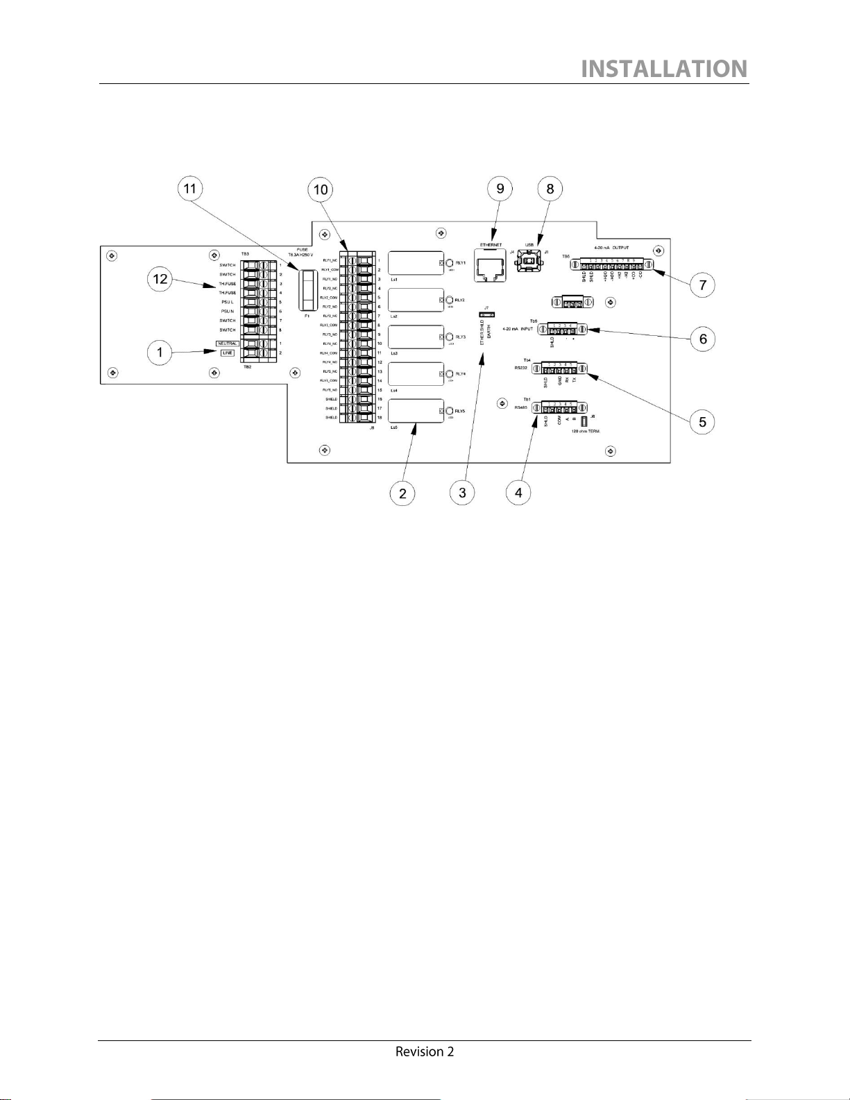
Calisto Interface Board Components:
12. Thermal cut-off fuse terminals
Items 8, 9 and 3 are respectively the USB type B port, the Ethernet port and the Ethernet shield
earth jumper. The USB port is for local connection only, used during servicing or maintenance of
the instrument.
1. Main supply terminals
2. Programmable relays with activity LEDs (5)
3. Ethernet shield earth jumper
4. RS-485 communication port
5. RS-232 communication port
6. 4-20mA analog input terminals
7. 4-20mA analog output terminals (3rd channel is for
Calisto 2 only)
8. Local USB type B port
9. Ethernet communication port
10. Programmable relay terminal block
11. Main supply fuse (5HT 6.3-R)
Figure 5: Calisto/Calisto 2 - Interface Board Components
15
Page 22
RATING
NOMINAL VALUE/RANGE
Connection range
2.50 – 4.00 mm2 solid
Connection range (UL/CSA)
14 – 12 AWG
Wire strip length
9 mm (~3/8 in.)
Wire insulation ratings
300V,
90ºC (194ºF) or better
Flammability
VW-1 or better
Screw type
M2.5
WARNING
Install the protective earth conductor to the earth ground terminal before making any
other connections. When uninstalling the unit, remove all other connections before
removing the protective earth connection.
Protective earth connection is essential to guarantee client safety. To install the protective earth
conductor to the earth ground terminal, secure the protective earth conductor tightly using the two
screw terminals provided. It is the client’s responsibility to ensure the integrity of the ground cable
and client-side ground connection.
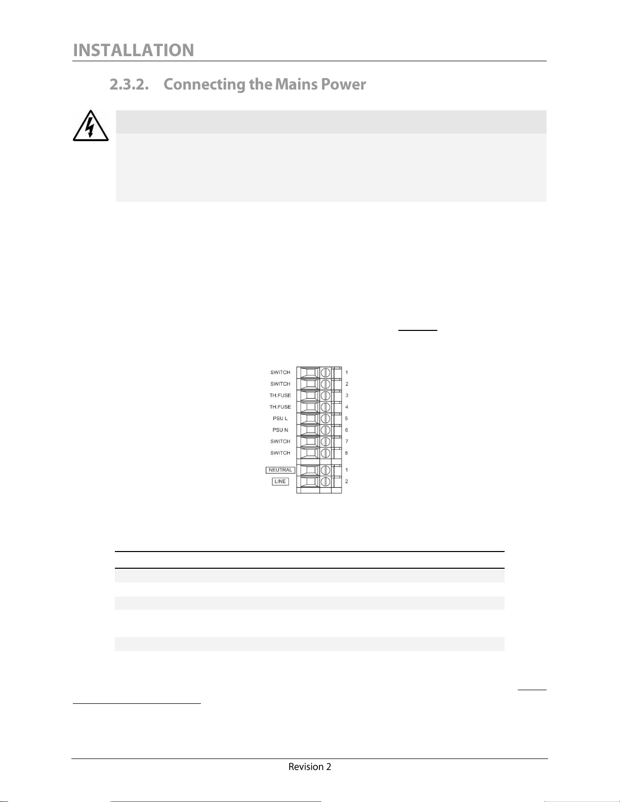
The Calisto/Calisto 2 monitor is designed to accept any supply voltage from 100 to 240 VAC with
frequencies in the range of 50 to 60 Hz. Mains power connections are made to connector 1 (neutral)
and connector 2 (line) using either solid or stranded conductors (See Figure 6). Connections must be
made in accordance with the connector ratings provided in the table below.
Figure 6: Calisto/Calisto 2 - Power Connections
To connect the mains power, loosen completely each screw terminal, insert the conductor to the
bottom of the terminal slot, and then tighten the screw.
16
Page 23
The Calisto/Calisto 2 nominal power is 320W. The main supply switch may be used to turn the unit
WARNING
Electrical shock hazard. Alarm relays may be connected to hazardous live voltage even
if the mains power is OFF or disconnected.
ON or OFF. A circuit breaker must also be dedicated to the unit for this purpose. Although the
Calisto/Calisto 2 is equipped with an internal over-current fuse, it is strongly recommended that a
suitable fuse or breaker be installed in the mains supply external to the unit, with rating appropriate
to the supply voltage and nominal power.
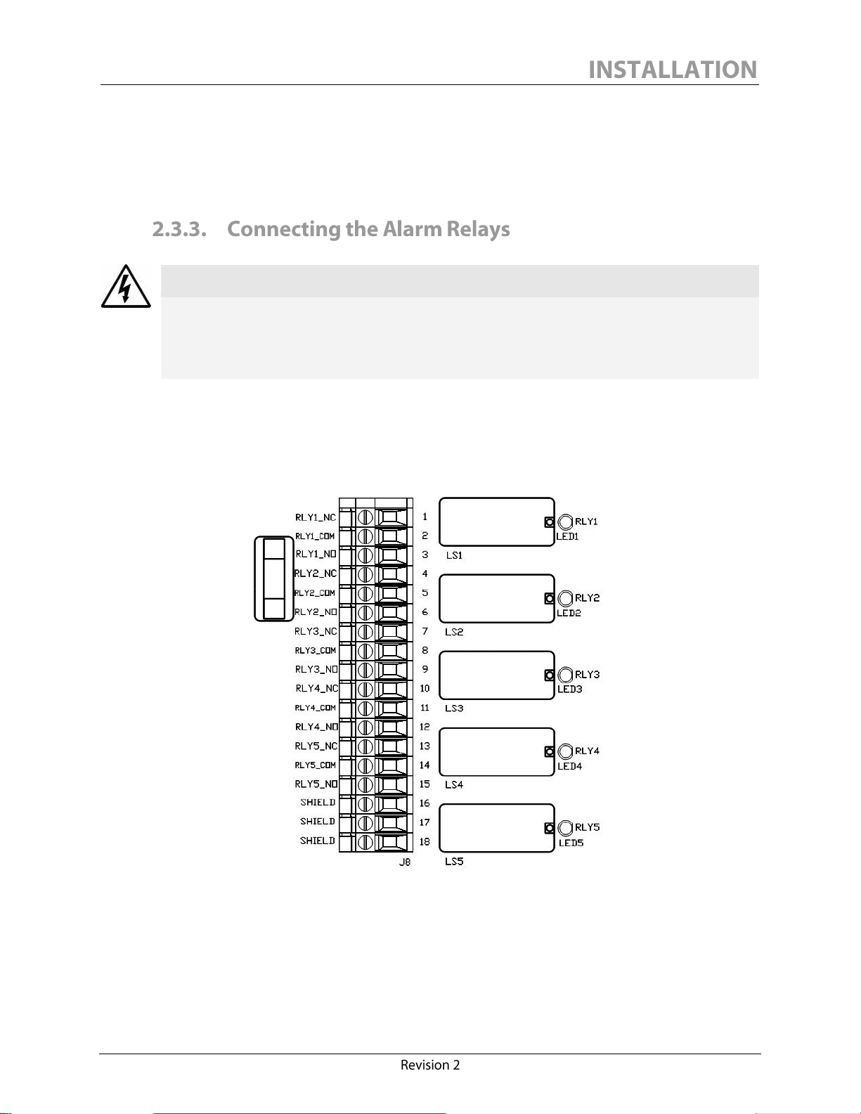
Calisto/Calisto 2 features 5 programmable dry-contact relays. Each relay can be connected in a
normally open (NO) or normally closed (NC) configuration.
All 5 relays are located on the monitor interface board as shown in Figure 7.
Figure 7: Calisto/Calisto 2 - Alarm Relays and Connections
17
Page 24
The table below describes the alarm relay connections pinout assignment:
CONNECTOR NO.
MARKING
CONNECTION TYPE
1
RLY1_NC
Relay 1 normally closed (NC)
2
RLY1_COM
Relay 1 common
3
RLY1_NO
Relay 1 normally open (NO)
4
RLY2_NC
Relay 2 normally closed (NC)
5
RLY2_COM
Relay 2 common
6
RLY2_NO
Relay 2 normally open (NO)
7
RLY3_NC
Relay 3 normally closed (NC)
8
RLY3_COM
Relay 3 common
9
RLY3_NO
Relay 3 normally open (NO)
10
RLY4_NC
Relay 4 normally closed (NC)
11
RLY4_COM
Relay 4 common
12
RLY4_NO
Relay 4 normally open (NO)
13
RLY5_NC
Relay 5 normally closed (NC)
14
RLY5_COM
Relay 5 common
15
RLY5_NO
Relay 5 normally open (NO)
16
SHIELD
Shield to earth ground
17
SHIELD
Shield to earth ground
18
SHIELD
Shield to earth ground
RATING
NOMINAL VALUE/RANGE
Connection range
0.34 – 2.5 mm2 stranded
Connection range (UL/CSA)
22 – 141 AWG stranded
Wire strip length
9 mm (~3/8 in.)
Wire insulation ratings
300V,
90ºC (194ºF) or better
Flammability
VW-1 or better
Screw type
M2.5
1
Connectors 2, 5, 8, 11 and 14 are all commons and can be looped together into one single common
if all signals must route to the same location.
Connectors 16, 17 and 18 can be used to terminate an alarm cable shield to the earth ground.
The relay connections must be made in accordance with the following connector ratings:
To connect the relay connections, loosen completely each screw terminal, insert the conductor in
the terminal slot until the bottom is reached, and then tighten the screw.
Using gauge 14 conductors to wire the relays may dictate the use of a larger diameter protective conduit, thus enlarging
one of the electrical entry holes. Two entry holes can also be dedicated to the alarm relay wiring as an alternative.
18
Page 25
Recommended use of the alarm relays:
AC CONNECTIONS
Characteristic
Nominal value/range
Min./Max. switching voltage
5V/400VAC
Rated resistive load
16A/250VAC
Min switching current
5mA
Coil-contact dielectric strength
5000VAC
DC CONNECTIONS
Characteristic
Nominal value/range
Min./Max. switching voltage
5V/300VDC
Rated resistive load
16A/24VDC
1A/48VDC
0.4A/100VDC
0.3A/(150-300)VDC
Min switching current
5mA
Coil-contact dielectric strength
5000VAC
For more information on how to configure the alarm relays, refer to Section 4.2.6 Setting Alarm
Limits and Section 4.2.7 Relay Output Configuration of this manual. The factory default alarm relay
configurations can also be found at Section 4.2.7.
The Calisto monitor features two 4-20 mA analog outputs, one for dissolved hydrogen and one for
moisture. Calisto 2 features one additional 4-20 mA analog output dedicated to carbon monoxide.
All analog outputs are isolated to 1500 V.
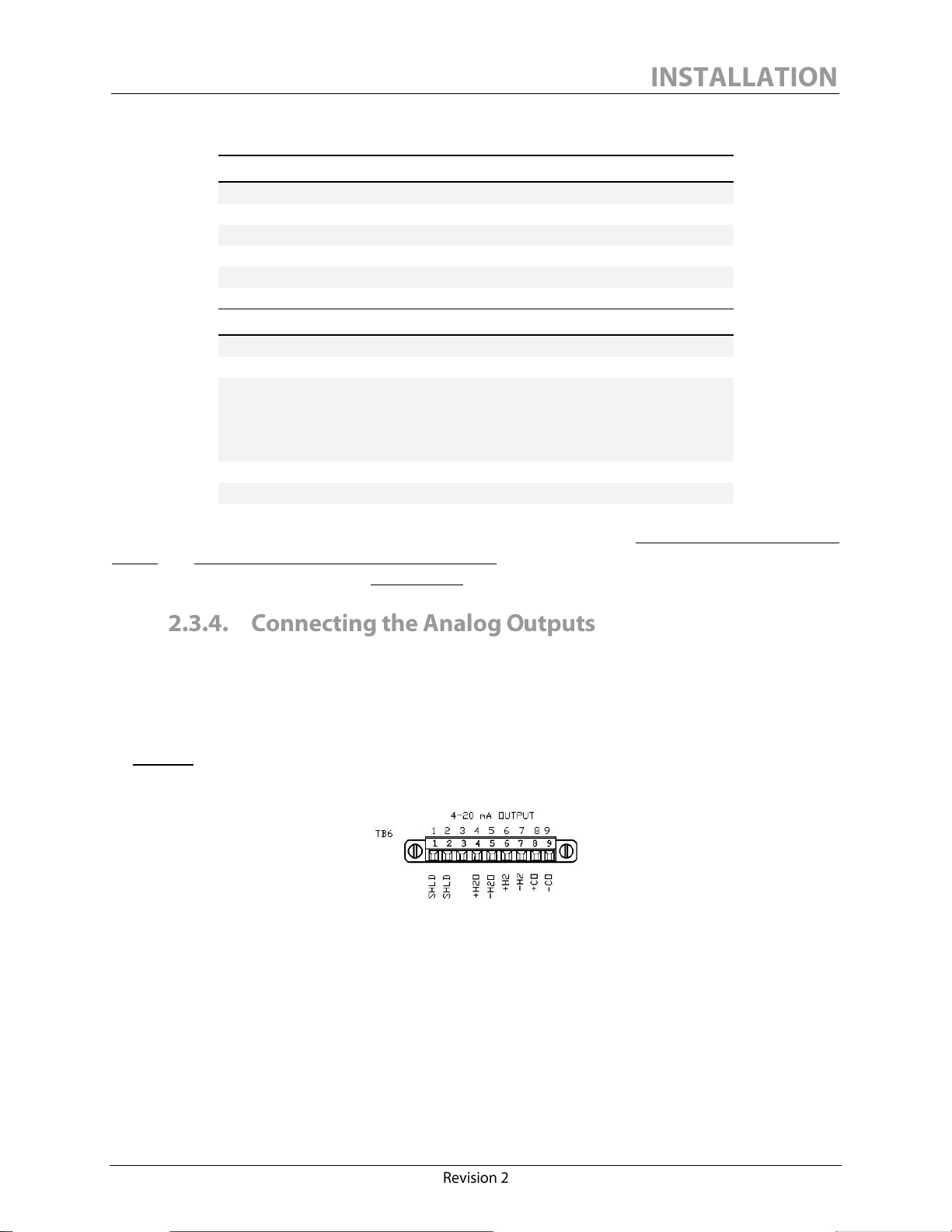
The analog output screw-terminal plug-in connector is located on the monitor interface board (Refer
to Figure 8). Although pin 8 and 9 are present in a Calisto monitor, no signal from this output can
be used as Calisto does not report carbon monoxide.
Figure 8: Calisto/Calisto 2 - Analog Output Connector
It is recommended to un-plug the connector to simplify wiring the connections, and to screw the
connector in place after the connections are made.
19
Page 26
The analog output connector pinout has the following configuration:
PIN NO.
OUTPUT
DESCRIPTION
1
SHLD
Shield to earth ground
2
SHLD
Shield to earth ground
3
N/A
Unused 4 Moisture (H2O)
Positive (+)
5
Moisture (H2O)
Negative (-)
6
Hydrogen (H2)
Positive (+)
7
Hydrogen (H2)
Negative (-)
8
Carbon monoxide (CO)
Positive (+) (Calisto 2 only)
9
Carbon monoxide (CO)
Negative (-) (Calisto 2 only)
RATING
NOMINAL VALUE/RANGE
Connection range
0.34 – 1.5 mm2 solid/stranded
Connection range (UL/CSA)
22 – 16 AWG
Wire strip length
6.5 mm (~1/4 in.)
Wire insulation ratings
150V (300V preferred2),
90ºC (194ºF) or better
Flammability
VW-1 or better
Screw type
M2.0
2
NOTICE
The analog input can only be used with self-powered 4-20 mA devices and must not be
powered by an external source.
The analog output connections must be made in accordance with the following connector ratings:
The load resistance can be anywhere from 0 Ohm to a maximum of 500 Ohms including resistance
of the wires. The maximum length of the wires depends on the overall resistance of the load and the
acceptable noise level.
The setup of the analog outputs is done using the Calisto Access software. Refer to Figure 33:
Calisto Access Default Set-Up for more information.
Calisto/Calisto 2 features one 4-20 mA analog input that can be used to provide a reading of the
transformer oil temperature to the unit. The 4-20 mA analog input is loop-powered to +13.5 VDC
and isolated to 1500 V.
To preserve 1500V functional I/O isolation, 300V rated voltage is preferred.
20
Page 27
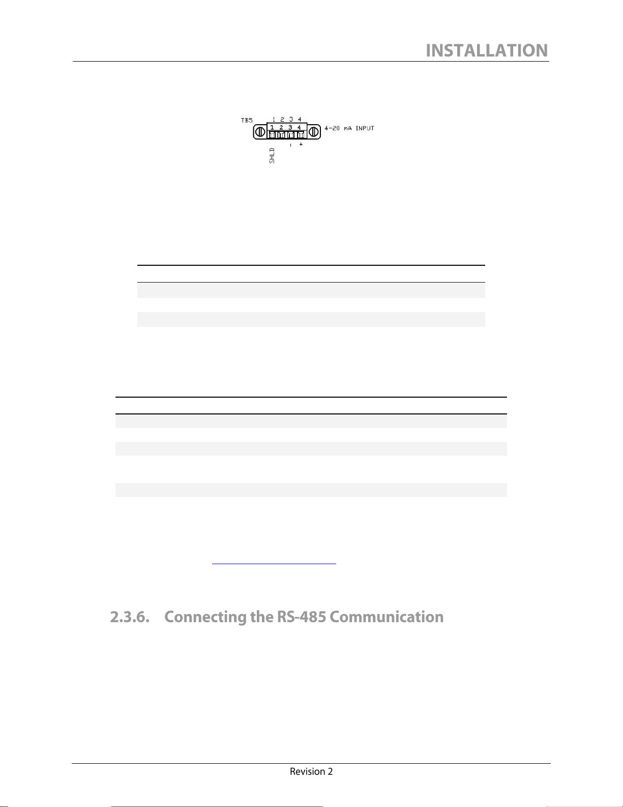
The analog input screw-terminal plug-in connector (Refer to Figure 9) is located on the monitor
PIN NO.
MARKING
DESCRIPTION
1
SHLD
Shield to earth ground
2
Unused 3 -
4-20 mA negative (-)
4
+
4-20 mA positive (+)
RATING
NOMINAL VALUE/RANGE
Connection range
0.34 – 1.5 mm2 solid/stranded
Connection range (UL/CSA)
22 – 16 AWG
Wire strip length
6.5 mm (~1/4 in.)
Wire insulation ratings
150V (300V preferred3),
90ºC (194ºF) or better
Flammability
VW-1 or better
Screw type
M2.0
3
interface board.
Figure 9: Calisto/Calisto 2 - 4-20 mA Analog Input Connector
It is recommended to un-plug the connector to simplify wiring the connections, and to screw the
connector in place after the connections are made.
The 4-20 mA analog input connector pinout has the following configuration:
The 4-20 mA analog input connections must be made in accordance with the following connector
ratings:
If the Precision Oil Temperature Probe option for Calisto/Calisto 2 was purchased with your
instrument, refer to the Precision Oil Temperature Probe Manual. An electronic version of this manual
can be found on our website www.morganschaffer.com.
The analog input temperature range is configured via the Calisto Access software.
Calisto/Calisto 2 features one RS-485 communication port isolated to 1500 V. The RS-485 uses a
differential balanced line over twisted pair and can thus span relatively large distances, up to 4000 ft
(1200 m). It is highly recommended to select an industrial grade shielded twisted pair cable of
minimum 0.34 mm2 (22 AWG) to set up a communication via RS-485.
To preserve 1500V functional I/O isolation, 300V rated voltage is preferred.
21
Page 28
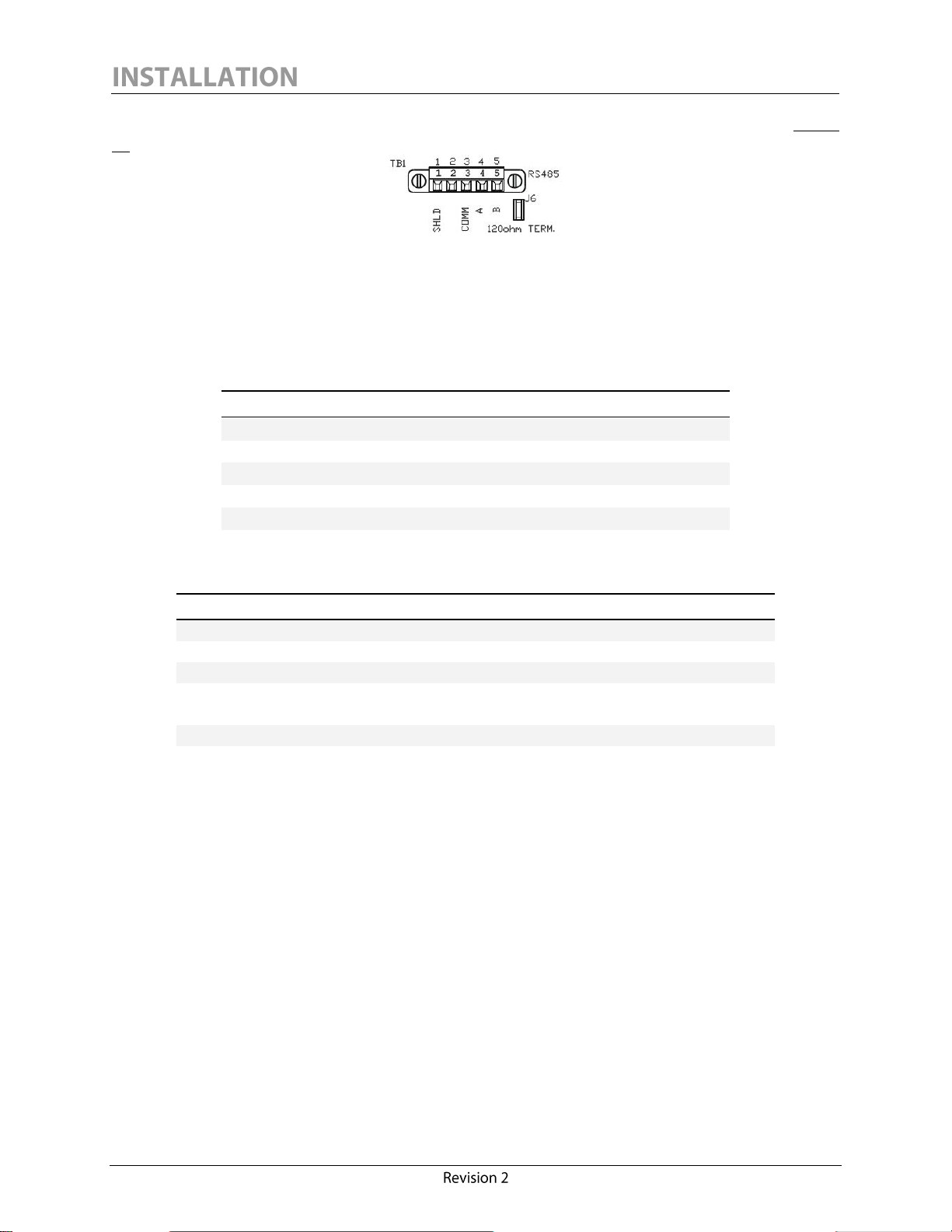
The RS-485 screw-terminal plug-in connector is located on the monitor interface board (See Figure
PIN NO.
MARKING
DESCRIPTION
1
SHLD
Shield to earth ground
2
Unused 3 COMM
Common signal ground
4
A
Line A 5 B
Line B
RATING
NOMINAL VALUE/RANGE
Connection range
0.34 – 1.5 mm2 solid/stranded
Connection range (UL/CSA)
22 – 16 AWG
Wire strip length
6.5 mm (~1/4 in.)
Wire insulation ratings
150V (300V preferred4),
90ºC (194ºF) or better
Flammability
VW-1 or better
Screw type
M2.0
4
10).
Figure 10: Calisto/Calisto 2 - RS-485 Connection
It is recommended to un-plug the connector to simplify wiring the connections, and to screw the
connector in place after the connections are made.
The RS-485 connector pinout has the following configuration:
The RS-485 connections must be made in accordance with the following connector ratings:
The RS-485 common signal ground (pin 3, marked “COMM”) should always be wired properly to
ensure a reliable connection. The signal ground of an RS-485 cable must not be connected to the
chassis ground or “SHLD” when optical or galvanic isolation is used at both ends. Since
Calisto/Calisto 2 provides 1500 V isolation, it is recommended to use RS-485 devices that also offer
good isolation. The signal ground conductor should be connected to pin 3 (COMM) and should be
connected at all ends.
To preserve 1500V functional I/O isolation, 300V rated voltage is preferred.
22
Page 29

CAUTION
Morgan Schaffer cannot be held responsible for a monitor communication malfunction
if the RS-485 cable shield is not properly attached to pin 1 (SHLD). For RS-485
communication, the common signal ground is not a shielding/earthing ground.
The monitor interface board provides a 120 Ohm terminating resistor which may be used to
terminate the RS-485 cable shield. The value of the terminating resistor is designed to match the
characteristic impedance of the cable, and may be useful in cases where the monitor is on the end of
an RS-485 network. Termination resistors are generally not required when communicating with a
Calisto/Calisto 2 monitor at the standard speed of 9600bps. To connect the terminating resistor,
install the jumper provided across J6 on the monitor interface board, just below the RS-485
connector.
However, to determine whether or not termination resistors should be used, the cable length and
data rate must be taken into account. If the propagation delay of the data line is less than one bit
width, termination should not be required. Reflections would dampen out in several trips up and
down the data line. Since the receiving device will sample the data in the middle of the bit, it is
important to have a good signal level at that point. The propagation delay can be calculated by
multiplying the cable length by the propagation velocity of the cable (usually specified by the cable
manufacturer, typically between 66% and 75% of the speed of light).
For example, in a system with 2000 feet of wire a round trip would cover 4000 feet. Using a
propagation velocity of 66% of the speed of light, a round trip would be completed in about 6.2µs.
If we assume the reflections dampen out in three round trips, the signal would stabilize 18.6µs after
the leading edge of a bit. At 9600bps one bit is 104µs wide: the reflections would be dampened out
before the center of the bit, and therefore termination resistors would not be required.
Calisto/Calisto 2 supports several protocols over RS-485:
MSSP (Morgan Schaffer Systems Protocol)
DNP3 (widely used protocol specific to the electric utility industry)
ModBus (widely used protocol in general automation industry).
Refer to Section 4.2.5 Communication Settings of this manual for more information on the above
protocols.
Calisto/Calisto 2 features one RS-232 communication port isolated to 1500 V. The maximum
recommended range for RS-232 communication is 15m (50 feet).
23
Page 30
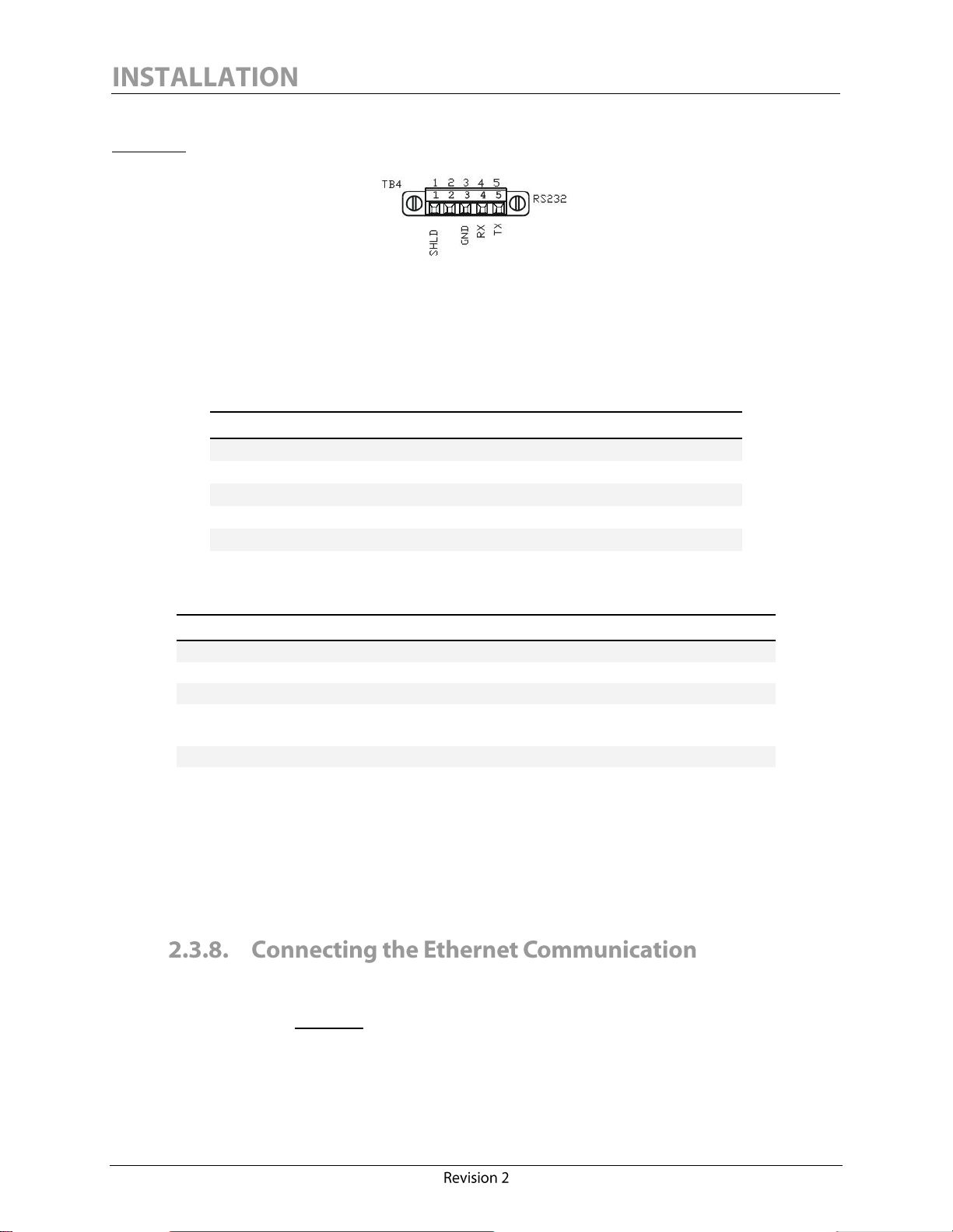
The RS-232 screw-terminal plug-in connector is located on the monitor interface board (see
PIN NO.
MARKING
DESCRIPTION
1
SHLD
Shield to earth ground
2
Unused 3 GND
Signal ground
4
RX
Received data
5
TX
Transmitted data
RATING
NOMINAL VALUE/RANGE
Connection range
0.34 – 1.5 mm2 solid/stranded
Connection range (UL/CSA)
22 – 16 AWG
Wire strip length
6.5 mm (~1/4 in.)
Wire insulation ratings
150V (300V preferred5),
90ºC (194ºF) or better
Flammability
VW-1 or better
Screw type
M2.0
5
Figure 11).
Figure 11: Calisto/Calisto 2 - RS-232 Connection
It is highly recommended to select an industrial grade shielded twisted pair cable of minimum 0.34
mm2 (22 AWG) to set up a communication via RS-232.
The RS-232 connector pinout has the following configuration:
The RS-232 connections must be made in accordance with the following connector ratings:
The RS-232 signal ground (pin 3, marked “GND”) should always be wired properly to ensure a
reliable connection.
The Calisto/Calisto 2 RS-232 communication port does not support any protocol other than our
proprietary MSSP.
Calisto/Calisto 2 features one Ethernet port which allows the unit to be connected to a computer or
a corporate LAN or WAN. The port is isolated to 1500 V. The port connector is located on the
monitor interface board. Figure 12 illustrates the onboard RJ45 receptacle that can be shielded using
jumper J7 (Ethernet shield to earth ground).
To preserve 1500V functional I/O isolation, 300V rated voltage is preferred.
24
Page 31

RATING
NOMINAL VALUE/RANGE
Connection range
0.34 – 1.5 mm2 solid/stranded
Connection range (UL/CSA)
22 – 16 AWG
Wire strip length
6.5 mm (~1/4 in.)
Screw type
M2.0
Figure 12: Calisto/Calisto 2 - RJ45 Ethernet port
For installing an Ethernet link, it is recommended to use an industrial FTP or ScTP cable suitable
for outdoor use (oil and sun resistant), even if a protection conduit is used. Proper connectors and
fittings must be used to preserve the ingress protection of the monitor. This type of connection
should not span over 30 m (100 ft).
The Ethernet connection must be made in accordance with the following connector ratings:
An FTP or ScTP shield must be connected to earth ground at only one end. Jumper J7 should only
be connected if the cable shield remains disconnected on the client’s side. Grounding at both ends
may lead to poor communication and/or damage to the instrument.
IEC61850 protocol (optional)
Calisto/Calisto 2 supports the IEC61850 substation protocol. This option can be selected at the
moment of the order and can also be retrofitted to any Calisto version C76-00000 or Calisto 2.
Ethernet Outdoor Connectivity Kit (optional)
For an easy and reliable connection, the Calisto/Calisto 2 monitor can be installed with the Morgan
Schaffer Ethernet Outdoor Connectivity Kit. This kit includes an IP68 industrial Ethernet shielded
patchcord (custom length, refer to Figure 13) fitted with screwable end connectors and all required
hardware to interconnect the monitor to a control panel. No protective conduit is required for this
highly abrasion-, oil- and UV-resistant cable.
Figure 13: Ethernet Outdoor Connectivity Kit Patchcord
25
Page 32

INSTALLATION NOTES
Below are guidelines for the installation of the Ethernet Outdoor Connectivity Kit:
The RJ45 pass-through bulkhead provided requires a 1-inch hole and must be
installed on a control cabinet.
UV stabilized cable ties are provided to secure the Ethernet patchcord.
Avoid installing the patchcord in any working or walking area.
The patchcord shield must be connected to the ground for interference
immunity. A Calisto/Calisto 2 monitor ordered with an Ethernet Outdoor
Connectivity Kit will have jumper J7 linking the onboard RJ45 receptacle shield
to the earth ground. Thus, the client has no need to connect the shield on his
side.
Avoid sharp bends to the cable.
Morgan Schaffer cannot guarantee protection from an external surge (such as lightning or electrical
arc) over 1500 V that could infiltrate the Ethernet line. It is the client’s responsibility to isolate the
Ethernet line on the client side.
Calisto/Calisto 2 supports several protocols over Ethernet:
MSSP (Morgan Schaffer Systems Protocol)
DNP3/TCP (widely used protocol specific to the electric utility industry)
Modbus (widely used protocol in general automation industry).
Refer to Section 4.2.5 Communication Settings of this manual for more information on the above
protocols.
The Calisto/Calisto 2 interface board includes a Type B USB jack. The USB connection does not
provide high voltage isolation and is therefore only suitable for local connection using a laptop
computer. This connection is convenient for the initial configuration of communication and other
settings. Driver installation is required in order to communicate over USB. Refer to 4.2.1 Installing
Calisto Access Software.
26
Page 33

NOTICE
When installing a Calisto/Calisto 2 monitor with a Precision Oil Temperature Probe, a
special probe fitting must be attached to the transformer valve before installing the oil
SUPPLY line. Refer to the Precision Oil Temperature Probe Manual.
To ensure representative sampling of the transformer oil, it is important that the oil inlet and outlet
valves on the transformer be distant as stated in the following section, to prevent oil re-circulation.
The valves should have a minimum diameter of 1.3 cm (½ in.), and be located near the
monitor.
Optional shutoff valves (preferably ball valves) are recommended below the monitor on the
oil RETURN and SUPPLY lines to isolate the monitor if unmounting is required.
Female, ball or gate type valves with a minimum diameter of ½ NPT are recommended for
the transformer valves.
The inlet and outlet valves must not be close to a pump.
The oil RETURN line must not exceed 11 m (35 ft).
The oil SUPPLY line must be longer than 1 m (3 ft) to reduce mechanical stress.
The distance between the two transformer valves should be a minimum of 1 m (3 ft).
The inlet valve should be at least 0.45 m (18 in.) above the main tank bottom.
Do not make straight lines between the transformer tank and the monitor. Include one loop
or bend in the oil line.
In very hot conditions, it is strongly recommended not to insulate the oil lines.
In very cold conditions, it is strongly recommended to permanently insulate the oil lines.
Most transformer manufacturers will install two 1.3 cm (½ in.) oil valves directly on the main tank
close to the location where the monitor will be installed. Both of these valves will generally be
accessible from the ground level.
27
Page 34
Calisto/Calisto 2 requires two oil valves from the transformer. Typically the top oil fill valve and the
bottom main drain valves are used. The preferred method is to draw oil from the top fill valve and
return the oil through the bottom main drain valve. This can only be done if the top oil fill valve is
below the top oil level. If the top oil valve is above the top oil level it will be necessary to draw oil
from the bottom main drain valve and return it through the top oil fill valve. Drawing oil from the
bottom main drain valve can pose some problems if there is an excessive amount of sludge from oil
decomposition in the bottom of the transformer. Also, condensed water may accumulate at the
bottom of very wet transformers.
Here are some suggestions for determining whether the top oil valve is below the top oil level:
Contact the transformer manufacturer.
Contact the responsible party within your organization.
Review the Outline drawings of the transformer and look for notes or review the instruction
book supplied with the transformer.
Some transformers have a conservator tank. A conservator tank is a large cylindrical or
rectangular tank that sits above the transformer main tank. A pipe connects the conservator
tank to the main transformer tank. If this is the case, the top oil valve on the main tank will
be below the top oil level.
Compare the location of the oil level gauge to the location of the top oil fill valve. If the
location of the oil level gauge is above the location of the top oil fill valve, most likely the
top oil fill valve is below the top oil level. If the top oil valve is higher than the location of
the oil level gauge, most likely the top oil fill valve is NOT below the top oil level.
Review the small print on the transformer nameplate. Often there is a statement indicating
that the top oil level is X below the highest manhole cover on the top of the transformer.
Compare this measurement to the location of the top oil fill valve.
Refer to Figure 1 and Figure 2 to view the oil inlet and outlet ports of the Calisto/Calisto 2 monitor.
28
Page 35
CAUTION
If a Precision Oil Temperature Probe is to be installed with the monitor, a provided tee
fitting must be installed instead of an elbow on the oil SUPPLY valve. Refer to the
Precision Oil Temperature Probe Installation Manual.
Figure 14: Tee Fitting Assembly for the Precision Oil Temperature Probe Option
Prior to installing the oil lines, both transformer valves selected to circulate oil to the monitor must
be prepared to accept the tube fittings included in the accessories. Figure 15 shows one of the
supplied brass elbow fittings 3/8″ tube to ½″ NPT male (stainless steel 316 if stainless steel flexible
oil lines were ordered with the monitor). If required, use a pipe adapter to fit the ½″ NPT male end
to the transformer SUPPLY and RETURN valves (Refer to Figure 16).
Figure 15: Transformer Valve Elbow Fitting
29
Figure 16: Adapting the Transformer Valve
Page 36

CAUTION
When attaching oil lines to the Calisto/Calisto 2, use a counter-torque wrench to avoid
damaging the INLET and OUTLET ports on the monitor. The torque and the
counter-torque wrenches must be aligned one over the other as much as possible to
cancel induced forces. A pipe-cutter must be used to cut the oil lines. Other tools must
be avoided as they can leave burrs, debris and scratches on the surface to be swaged.
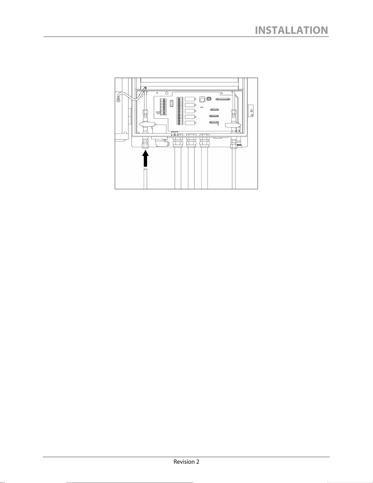
1. Install the first oil line as follows: Unroll a few inches of one of the supplied coils of 3/8″
copper tubing and insert one end firmly into the monitor INLET port (See Figure 17). Using
an 11/16 wrench and a 5/8 counter-torque wrench, tighten the compression nut 1¼ turns
from finger tight for proper sealing. Route the tubing properly to the transformer SUPPLY
valve and cut off the excess length using a pipe cutter. Deburr the inside of the tube to
prevent flow restriction. Both ends of the tubing should be straight for several inches where
they enter the fittings. Incorporate at least one shallow bend somewhere in the tubing to aid
installation. Tighten the tubing at the transformer SUPPLY valve (or at the tee fitting
assembly when installing a Precision Oil Temperature Probe option) to complete the oil
SUPPLY line installation.
Figure 17: Attaching the Copper Tubing to the INLET Port
2. Install the second oil line as follows: Unroll a few inches of the second supplied coil of 3/8″
copper tubing and insert one end firmly into the monitor OUTLET port (See Figure 18).
3. Using an 11/16 wrench and a 5/8 counter-torque wrench, tighten the compression nut 1¼
turns from finger tight for proper sealing. Route the tubing properly to the transformer
RETURN valve and cut the excess length of tubing using a pipe cutter. Deburr the inside of
30
the tube to prevent flow restriction. Both ends of the tubing should be straight for several
Page 37
inches where they enter the fittings. Incorporate at least one shallow bend somewhere in the
tubing to aid installation. Tighten the tubing at the transformer valve to complete the oil
RETURN line installation.
Figure 18: Attaching the Copper Tubing to the OUTLET Port
4. Secure all oil lines against excessive vibration.
31
Page 38

CAUTION
Before continuing, Section 5.1 of the Precision Oil Temperature Probe Installation Manual
must now be followed when the option is to be installed with a Calisto/Calisto 2.
NOTICE
The Calisto/Calisto 2 monitor is equipped with a proprietary gas accumulator which
will vent any air bubbles present in the incoming oil, once the monitor is in operation.
1. Once all connections are made, the lines and the monitor must be flushed with oil to remove
any air present in the assembly and to replace the shipping oil inside the monitor with oil
from the transformer. To do so, ensure that both monitor valves are still closed (valve
handles in the horizontal position, refer to Figure 19), then slowly open both transformer
valves.
Figure 19: Monitor with Both Valves Closed
2. Firmly push the supplied Quick Connect Oil Sampling Tube (fitted with ¼" yellow plastic
tubing, refer to Figure 20) into the monitor’s oil SAMPLING port located at the bottom of
the enclosure (beside the oil INLET port, refer to Figure 21).
32
Page 39

Figure 20: Quick Connect Oil Sampling Tube
Figure 21: Connecting the Quick Connect Oil Sampling Tube to the monitor
3. Using a container to collect the flushed oil, slowly turn the OUTLET valve (left side)
counterclockwise ¼ turn (the handle will then be pointing down) to flush the RETURN line
with oil (Refer to Figure 22: Flushing the Oil RETURN ). To avoid injecting trapped air in
the transformer, flush a minimum of 500 cc of oil and then close the OUTLET valve by
turning it clockwise to the horizontal position.
33
Page 40

NOTICE
Before proceeding with Step 5, the following checks should be made:
The earth ground is properly connected.
The mains power is protected by a circuit breaker.
The main supply switch is in the “O” position (OFF).
Both transformer oil supply and oil return valves are open.
Both monitor oil INLET and oil OUTLET valves are closed.
Figure 22: Flushing the Oil RETURN Tube
4. Slowly turn the INLET valve (right side) counterclockwise ¼ turn to the vertical position to
flush the SUPPLY line with oil. Now, turn the main supply switch to the <I> (ON) position
to start the internal oil circulation pump to enable flushing (See Figure 23). To avoid
injecting trapped air into the transformer, wait until a minimum of 500 cc of oil is flushed
again and turn the main supply switch to the <O> position (OFF).
34
Page 41

Figure 23: Flushing the Oil SUPPLY Tube
5. While maintaining the INLET valve open, remove the Quick Connect Oil Sampling Tube
from the oil SAMPLING port by pushing the locking ring up and pulling the fitting (with
yellow hose) down (See Figure 24).
Figure 24: Disconnecting the Quick Connect Oil Sampling Tube from the Monitor
6. Open the OUTLET valve (left side). At this stage, both transformer valves and both
monitor valves should be open as shown in Figure 25.
35
Page 42
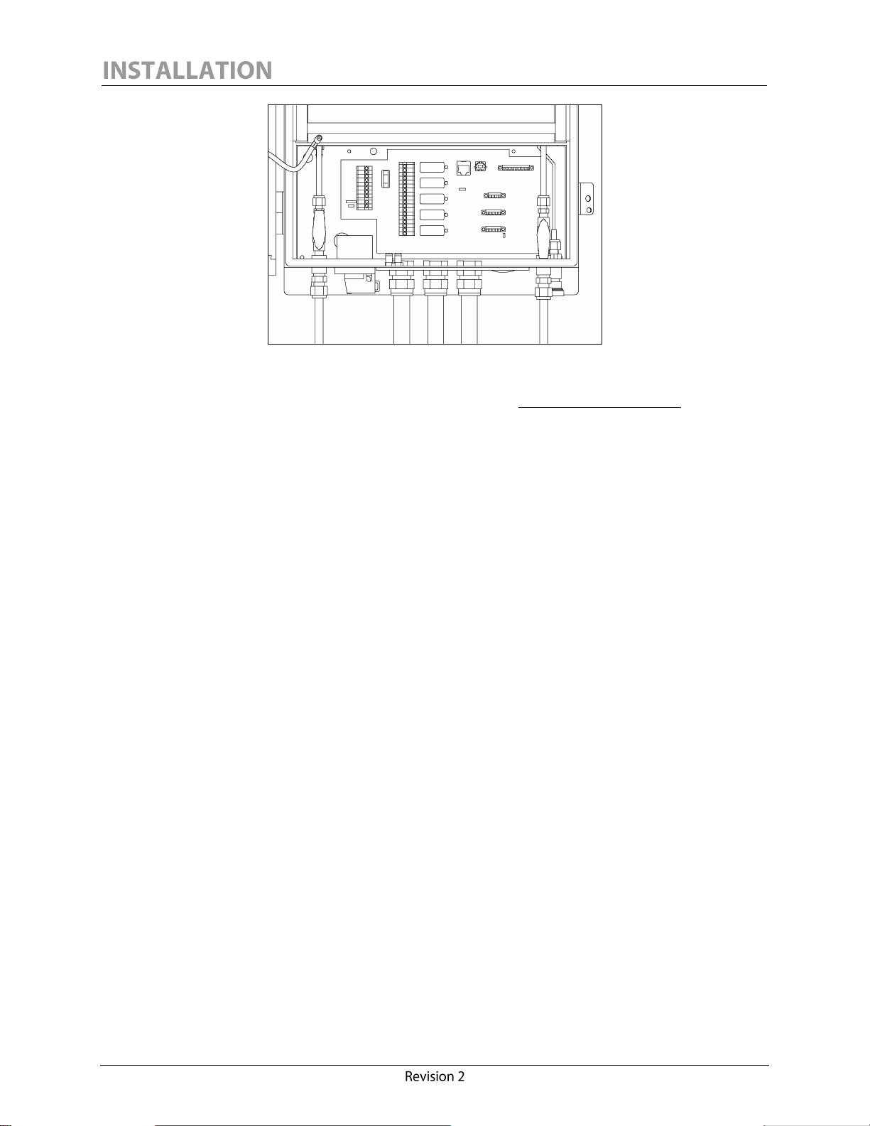
Figure 25: Monitor with both Valves Open
7. The monitor is now ready for configuration. Refer to Section 3.0 POWER UP.
36
Page 43

Before starting the installation, ensure that the monitor main supply switch is in the <O> position
(OFF), and that the INLET and OUTLET valves inside the monitor are closed (horizontal
position).
1. Bolt the IED to a proper structure or a Morgan Schaffer Calisto Mounting Stand using the
provided vibration mounts.
2. Connect the earth ground and mains power.
3. Connect the alarm relays (if required).
4. Connect the analog 4-20mA outputs (if required).
5. Connect the analog 4-20 mA input (if required).
6. Connect the RS-485 or RS-232 or Ethernet line (if required).
7. Prepare the transformer SUPPLY and RETURN valves.
8. Connect the copper tubing (or stainless steel braided hoses) to the transformer valves and to
the corresponding oil INLET and OUTLET ports.
9. Connect the supplied Quick Connect Oil Sampling Tube to the sampling port and use a
container to purge the oil RETURN line.
10. Open both transformer valves.
11. Open the OUTLET valve and purge 500 cc of oil from the monitor RETURN line.
12. Close the OUTLET valve.
13. Open the INLET valve and power ON the monitor to pump oil through the SAMPLING
port. Purge 500 cc and power OFF the monitor.
14. Disconnect the Quick Connect Oil Sampling Tube from the SAMPLING port (do not close
the INLET valve).
15. Open the OUTLET valve.
16. The monitor is ready to be configured. Refer to Section 4.0 INSTRUMENT SETUP AND
OPERATION.
37
Page 44

Page 45

The following checks should be made before providing power to the monitor:
Verify that no tools or other equipment are present in the enclosure.
The earth ground is properly connected.
The mains power is properly connected.
All signal, relay and communication wiring is installed.
The monitor is protected by an appropriate circuit breaker.
Both transformer oil SUPPLY and RETURN valves are open.
Both instrument oil INLET and OUTLET valves are open.
All conduit fittings are fully tightened (rubber plugs are present on unused entry holes).
Verify that the instrument has a 0.6 m (24 in.) minimum clearance from the ground.
Verify that there are no excessive vibrations on the complete system.
Verify that the oil line connections have no leaks.
39
Page 46
NOTICE
If the instrument temperature is below -35oC (-31°F) at start-up, the IED will enter
into a pre-heating mode where only the enclosure heaters will be activated. The
instrument on-board computer will start once the enclosure temperature has
reached -5oC (41°F). Reaching the computer start-up temperature could take several
minutes or even hours in extremely cold environments.
Once the instrument has been properly installed and the checks in Section 3.1 have been made, the
instrument can be started by providing power to the unit and placing the main supply switch to the
<I> position (ON). A delay of approximately 5 seconds will occur before a reading is displayed on
the door display. This time is required by the instrument for firmware initialization.
When the Calisto/Calisto 2 is powered on or reset, the unit first enters an initialization and poweron self-test sequence. The purpose of this mode is to allow the on-board computer to evaluate
temperature conditions and to allow the detection cell and moisture sensor to reach equilibrium with
the surroundings. The duration of the initialization is 3 hours or one complete measuring cycle.
During the entire time of this mode of operation, the door display will indicate <H2= INIT> to
inform the user of this normal condition.
After completing this initialization sequence, the unit will then enter into its normal mode of
detection and measurement, thereby displaying the last validated measurement for hydrogen
<H2=000>. Carbon monoxide (Calisto 2 only) and moisture measurements can also be viewed on
the display using the 3-button display interface. Refer to Section 3.3 for a complete description of
the display interface operation. All readings will then be updated after the next measurement cycle,
and subsequently time-stamped and stored as new validated measurement records in the on-board
databank.
40
Page 47
The 3-button display interface provides access to three different “sections” of information: Realtime
<REALTIME>, Manufacturer <MANUFACT> and Database <DATABASE>. Buttons 1 and 2
pushed simultaneously are used to toggle between sections. Button 3 is used to scroll between fields
within the same section. Refer to Figure 26 for a complete overview of the display interface
structure. Data are shown as examples only.
Realtime Section
By default, the instrument will show the last validated concentration of hydrogen <H2=000> under
the section <REALTIME>. For a quick overview of all current measurements, button 3 must be
pressed three times to see consecutively the carbon monoxide <CO=000>, the moisture
<WRS=00> and the oil temperature <OTT=00>. With a Calisto version C76-00000, <CO=N/A>
will be displayed while trying to access the carbon monoxide measurement. By default, moisture is
displayed as <WRS=00> for % relative saturation at 25oC (77°F), and the oil temperature will
display <OTT=NONE> (inactive by default). Using the Calisto Access software provided, the
moisture can be set up to show a % relative saturation at user selectable temperature <WST=00> or
a concentration in ppm <WWC=00>. Note that user selectable temperature requires a Calisto
Precision Oil Temperature Probe connected through the 4-20mA analog input. Refer to Section
4.2.11 External Input Sensor Configuration.
Manufacturer Section
To browse the monitor’s Manufacturer section, press once on buttons 1 and 2 simultaneously from
the default display to access all the instrument information. Press Button 3 to access each field of
the Manufacturer section (refer to Figure 26). This section provides useful information about the
instrument such as the Serial Number, the firmware version and the date of manufacturing. The unit
will return to the default section <REALTIME> after 10 seconds of inactivity.
Database Section
To browse the monitor’s database, press buttons 1 and 2 simultaneously twice from the default
display to access all recorded data. Press Button 3 to access the record number and then press
Button 1 to scroll down all data one by one, starting from the most recent record to the oldest
record: example <REC=299> to <REC=001>. Press Button 2 to scroll up to the newest record.
At any time, at any record number, Button 3 can be pressed to scroll through the fields of a specific
record. For more information, refer to Figure 26 which shows the structure of the display interface
for Calisto/Calisto 2. For a Calisto model C76-00000, the same structure applies, except that CO
will be shown as <CO=N/A>. The unit will return to the default section <REALTIME> after 10
seconds of inactivity.
Trends cannot be seen via the display.
At any time, the user may get back to the current readings by pressing buttons 1 and 2
simultaneously until <REALTIME> is displayed. <H2=000> will be displayed after a few seconds.
41
Page 48

Figure 26: Calisto/Calisto 2 Display Interface Structure
42
Page 49
Page 50

WARNING
Electrical shock hazard. Only persons with electrical safety training and certification
should install the equipment or open the enclosure once the equipment has been
installed.
Calisto/Calisto 2 can be set up for local, remote (hard wired) or wireless communication (not part of
this manual).
Calisto/Calisto 2 is supplied with a 1.8 m (6 ft) A/B type USB cable (Refer to Figure 27). The USB
port is dedicated to the monitor configuration, setup and maintenance.
Before connecting the USB cable to the monitor, open the door and access the monitor interface
board. Connect the USB cable to the interface board port (type B) and to your portable computer
port (type A).
Figure 27: 6-Feet Long A/B Type USB Cable
43
Page 51
6
This section describes the use of the Calisto Access software to quickly configure and commission a
Calisto/Calisto 2.
To install Calisto Access, insert the Calisto/Calisto 2 CD-ROM and wait for the Setup window to
appear. Follow the on-screen instructions. At the Choosing Components step of the Calisto
Access installation, make sure to check the USB Drivers box. A notification window may appear;
choose the Continue Anyway option. At the end, Calisto Access setup will give the choice to
immediately launch Calisto Access, or not. Refer to the next section before performing the first
startup.
Prior to starting Calisto Access, your computer should be properly connected to the monitor using
the supplied USB cable and proper drivers should be installed when asked by the operating system6.
Press the Start button, select Programs, choose the Morgan Schaffer group and press on the
Calisto Access icon. The software will automatically try to locate the proper communication port
that is linked to the monitor.
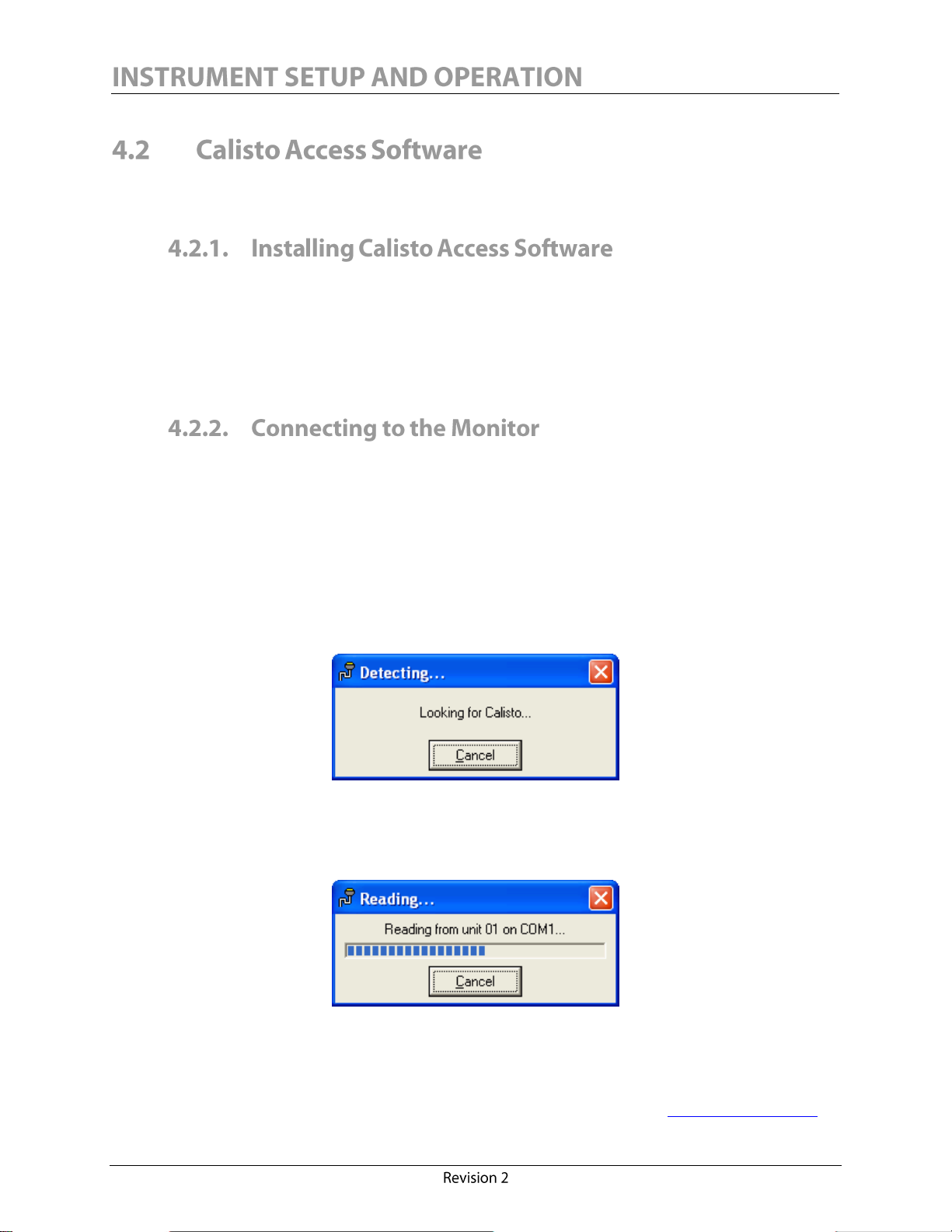
The screen shown below will appear if no problems are encountered during the communication
initialization sequence.
Once a Calisto/Calisto 2 unit has been detected, the following screen will indicate the progression of
the initial information readings from the unit. These readings are necessary to retrieve the basic
settings of the monitor.
After a one minute timeout, the following message will appear if Calisto Access cannot find the port
currently used for communication with the IED.
If you have issues with the USB connection or material, refer to the help document on the Morgan Schaffer website.
44
Page 52

Click OK, check the cable connections at both computer and IED ends and try to initiate
communication manually. To do so, in the Communication/Configuration menu, click Modify.
Be sure that in the Communication Link window the configuration is as follows:
RS232 None None RS232.
Click
Use this configuration.
Select the serial COM port value from the Computer Port combo-
box. It must be the same COM port as the one you selected to communicate with.
To confirm which port is used, see My Computer / Properties / Hardware / Device Manager /
Ports (COM & LPT). The path for accessing Device Manager may differ, depending on your
system. The line representing the Calisto/Calisto 2 is: IAR Virtual COM port, IAR STR912-SK
board.
45
Page 53

COM4 in this example
Different connection steps may appear depending on your selected communication link. In the
event that the error message reappears, close and re-start the application. If the issue is still not
resolved, please contact Morgan Schaffer for assistance, either by e-mail at
support@morganschaffer.com or by phone at 001.514.739.1967.
The Calisto Access Status tab displays information about the currently connected unit. This screen
appears once communication is established with that specific unit. In the first subdivision of the
Status tab, the Unit Description information is found: the Calisto Model, Serial Number and Firmware
Version.
46
Page 54

Figure 28: Calisto Access Status Tab with an Error Code
The Current Readings subdivision contains various measurements and trend values. The Validated H2
(ppm) field displays the last saved hydrogen value while the Continuous H2 (ppm) field shows the actual
continuous hydrogen concentration. Also, for Calisto 2 only, the Validated CO (ppm) field displays
the last saved carbon monoxide concentration. The H2O (ppm) field displays the actual ppm
concentration or the calculated moisture relative saturation, according to the current water
measurement mode set in the Measurements tab under H2O Measurements Mode section.
In case of malfunction, an error message will appear in the Status tab, see Figure 28. An error code
will be displayed along with the instrument components involved.
The Error Code Interpretation Chart, found in Figure 29, explains the hexadecimal-based error
code. This chart lists all possible error bits, their position and description. For example, the 8002
error code shown in Figure 29 is only an illustration of an error combination that could occur. This
error code will also appear on the monitor’s external LCD display. Refer to Table 1 for a description
of individual error codes.
47
Page 55

Figure 29: Error Code Interpretation Chart
48
Page 56

ERROR CODE
(HEXADECIMAL)
ERROR
NAME
DESCRIPTION
1
Outside
Fan
This error only occurs when heat sink temperature (ST
on display or OUTT in Calisto Real Time) is higher than
27°C (81°F) and the external fan is not running. In that
case, the fan is disconnected or has failed. Please contact
Morgan Schaffer for assistance, either by phone at
001.514.739.1967 or by e-mail at
support@morganschaffer.com.
2
Inside Fan
This error occurs when the internal fan is no longer
running. Open the door and manually check the air
flow. If no air circulation is found, the fan must be
replaced. Please contact Morgan Schaffer for assistance.
4, 8, 400, 4000
Detection
Cell
Please contact Morgan Schaffer for assistance.
10, 20, 40, 80, 100, 200
Thermal
Regulation
Please contact Morgan Schaffer for assistance.
1000
Moisture
Sensor
Please contact Morgan Schaffer for assistance.
2000
External
Input
This error occurs when analog input is not properly
connected or missing.
- Verify the current in the 4-20mA circuit with a
multimeter.
- Verify connections for 4-20mA input pinout; refer
to Figure 9.
- Validate the 4-20mA generator functionality.
If all the above are correct, please contact Morgan
Schaffer for assistance.
8000
Oil Flow
This error occurs when the oil flow is below the pre-set
threshold.
- Verify that all valves are open (transformer and
Calisto/Calisto 2).
- Take an oil sample using the Quick Connect Oil
Sampling Tube as described in Section 5.0, and
validate oil viscosity value.
If all the above are correct, please contact Morgan
Schaffer for assistance.
Table 1: Individual Error Code
49
Page 57

The Current Alarm States subdivision contains the H2, H2O and Trend alarm states. Calisto 2 also
NOTICE
Fields can be accessed using the mouse pointer or using the TAB key. New data will
only be sent to the IED if the ENTER key is pressed. Moving to the next field
without pressing the ENTER key will cancel changes made to the previous field.
features alarm states for CO. An alarm state is <ON> when the current reading exceeds the
corresponding alarm level. Alarm levels are configured in the Outputs tab, as discussed in Section
4.2.6.
The Current Relay States subdivision shows the actual state of the five output relays. A red LED
icon turns on when a relay is ENERGIZED. Hardware LEDs with the same functions can be seen
on the entry panel. The relationship between alarm and relay states is configured in the Outputs tab,
as discussed in Section 4.2.7.
New Calisto/Calisto 2 units are shipped with numerous operating parameters configured to Morgan
Schaffer factory defaults. Most of these parameters do not require client modification. However, to
take full advantage of the Calisto/Calisto 2 communications, alarms and analog I/Os, it is necessary
to adjust some settings to suit the specific transformer and installation.
To modify the unit information parameters, establish communication using Calisto Access (refer to
Section 4.2.2 Connecting to the Monitor) and edit the information in the Owner, Location,
Transformer ID, Date and Time fields.
50
Page 58

Figure 30: Calisto Access Settings Tab
The preferred method of adjusting the communication settings is through a local connection
between a laptop PC and the Calisto/Calisto 2 USB port. A few simple steps are required to
configure the communication settings, as discussed below.
Calisto/Calisto 2 units have three available ports that can be accessed and set to different baud rates
simultaneously and independently of each other. If a unit reboots, all ports will keep their baud rate
setting if it has been changed.
51
Page 59

RS-485 Communication
CAUTION
To ensure reliable operation in the face of possible security threats, the Calisto/Calisto
2 should not be connected to the Internet without encryption or password protection.
If there is a concern about the security of the LAN, a VPN router may be used to
connect the Calisto/Calisto 2 to the LAN with encryption security.
To communicate with other devices on an RS-485 network, each monitor must be assigned an RS485 ID (range 01 to 99) which is specific to that network. In a RS-485 network consisting of
multiple Calisto/Calisto 2 units, every unit is then available for connection. The RS-485 ID is used
as the monitor ID for all protocols: DNP3/RS485, DNP3/TCP, Modbus, MSSP (Morgan Schaffer
Systems Protocol).
Ethernet Communication
Each Calisto/Calisto 2 unit has an Ethernet interface, which requires a specific IP address, subnet
mask and gateway. Note that the IP address is normally specific, and that the subnet mask is
normally common to a group of Calisto/Calisto 2 units. The subnet mask defines your local
network boundaries. To obtain an appropriate IP Address and Subnet Mask for your monitor, contact
your network administrator.
DNP3 Protocol
If you are using RS-485 communication, select the DNP3 protocol in the RS-485 protocol field and
press the Configure button which appears. If you are using Ethernet communication, press the
Configure DNP3/TCP button. In both cases, a DNP3 Configuration window will appear; refer to
Figure 31 for RS-485 and to Figure 32 for Ethernet.
The Requires Data Link Confirmation parameter can be set to <ALWAYS> or <NEVER>. In the first
case, Request Link Reset is enabled, while in the second case it is disabled. Also, set the Maximum
Application Layer Retries parameter to the desired value [0 to 6]. Set the DNP3 Master Address
parameter to the desired value [1 to 99]. To allow Calisto/Calisto 2 to generate a Change Event for
one of the Binary Inputs or Analog Inputs, set the Class of those to Class 1, otherwise set it to
Class 0.
If using DNP3 on Ethernet, the TCP Connection Timeout (minutes) has to be set. Only one connection
is accepted by Calisto/Calisto 2 on the DNP3 port: 20000. Once established, this connection has to
be maintained by sending a “keep-alive” DNP3 message within the timeout specified by the TCP
Connection Timeout value.
To obtain the implementation table or for any other questions concerning the DNP3 protocol,
please contact Morgan Schaffer either by e-mail at support@morganschaffer.com or by phone at
001.514.739.1967.
52
Page 60
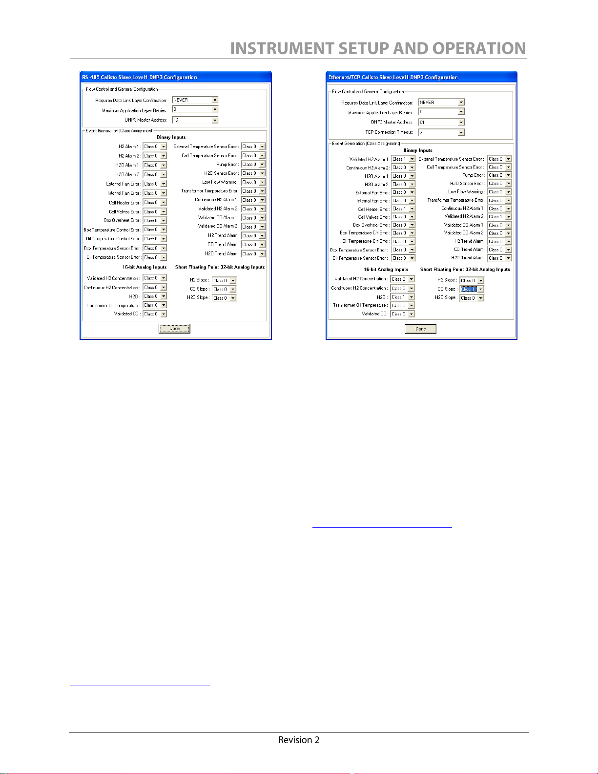
Figure 31: DNP3/RS485
Figure 32: DNP3/TCP
Modbus Protocol
Modbus protocol can be activated on the RS-485 communication port of Calisto/Calisto 2 and only
using the default settings, i.e. baud rate 9600, 8 Data bits (RTU); 7 Data bits (ASCII), No parity and
1 Stop bits. Both RTU and ASCII transmission modes are supported. The communication has halfduplex functionality such that a new query must await the response to the previous query.
The Modbus/TCP protocol can be accessed through port 502 at Ethernet 1. The Modbus/TCP
connection will automatically be closed by Calisto/Calisto 2 if no other query is issued within a three
hour period.
To obtain the implementation table or for any other questions concerning the Modbus protocol,
please contact Morgan Schaffer either by e-mail at support@morganschaffer.com or by phone at
001.514.739.1967.
IEC61850
If the Calisto/Calisto 2 unit has the IEC61850 option installed, it will be possible to change the IP
address, subnet mask and gateway of the IEC61850 module. Note that the IP address is normally
specific, and that the subnet mask is normally common to a group of Calisto/Calisto 2 units. The
subnet mask defines your local network boundaries. To obtain an appropriate IP Address and Subnet
Mask for your monitor, contact your network administrator.
To obtain the implementation table and the ICD file or for any other questions concerning the
IEC61850 protocol, please contact Morgan Schaffer either by e-mail at
support@morganschaffer.com or by phone at 001.514.739.1967.
53
Page 61
ALARM CONDITION
LEVEL
FACTORY
DEFAULT
Hydrogen
H2 Validated Alarm 1
H2 Continuous Alarm 1
LOW
1207 ppm
H2 Validated Alarm 2
H2 Continuous Alarm 2
HIGH
2407 ppm
Moisture
H2O Alarm 1
LOW
20%RS @ 25°C (77°F)
H2O Alarm 2
HIGH
40%RS @ 25°C (77°F)
Carbon
Monoxide
(Calisto 2
only)
CO Validated Alarm 1
LOW
1,0807 ppm
CO Validated Alarm 2
HIGH
2,1607 ppm
7
NOTICE
Morgan Schaffer recommends the following to establish the best levels of alarm limit
and trend values:
Work with the transformer manufacturer.
Consult an industry expert.
Carry out a statistical analysis of gas levels on a population of similar transformers
being used in similar loading conditions, environment, etc.
For both monitors, alarm limit values can be adjusted for dissolved hydrogen and moisture from the
Calisto Access interface, under Outputs. In the case of Calisto 2, carbon monoxide alarm limit
values can also be adjusted this way. For each transformer being monitored, alarm limit values
should reflect the actual concentrations of dissolved gases and moisture in accordance with the
client’s policies.
Factory default alarm limits are set as follows.
Trend values are calculated from the databank of validated readings, by linear regression across the
most recent trend period (day, week, or month). A trend of INIT is reported if fewer than 8
validated readings are available in the trend period. The trend calculation accommodates missed
readings, as may occur if the unit is turned off during part of the trend period. It is the client’s
responsibility to set the trend periods and trend limits to suit the transformer and the installation.
Alarm levels for H2 and CO are based on the typical concentration values of power transformers given in the
international standard IEC 60599.
54
Page 62

Note that short trend periods and low trend limits may increase the likelihood of false trend alarms.
ALARM
CONDITION
FACTORY
DEFAULT
TREND UNIT
Trend
H2 Trend Alarm
500
ppm/month
CO Trend Alarm
(Calisto 2 only)
2,000
ppm/month
H2O Trend Alarm
50
ppm/month
Factory settings for trend limit values are given in the table below:
Calisto/Calisto 2 is equipped with 5 N.O./N.C. dry-contact relays. Flexible relay configuration
options are provided under the Outputs tab of the Calisto Access interface, see Figure 33.
Each relay has two Response Modes. Usually, the <is energized> Response Mode is used. The
<blinks> Response Mode can be useful to confirm dynamically that relay connections are
operational.
Each relay response can be inverted if the Logic parameter is changed from the default <when>, to
<when not>.
Finally, the Condition to which the relay responds can be selected from a drop-down list which
includes Alarms, Errors and some combinations of Alarms and Errors.
55
Page 63

Figure 33: Calisto Access Default Set-Up
Relay Response
Mode
Condition
Logic
56
Page 64

The Conditions which can be assigned to each relay are:
1. Alarm Conditions. Alarms occur when measurements exceed configured limits. (See
Section 4.2.6. Setting Alarm Limits)
H2 Validated Alarm 1
H2 Validated Alarm 2
H2 Continuous Alarm 1
H2 Continuous Alarm 2
H2 Trend Alarm
H2O Alarm 1
H2O Alarm 2
H2O Trend Alarm
CO Alarm 1 (Calisto 2 only)
CO Alarm 2 (Calisto 2 only)
CO Trend Alarm (Calisto 2 only)
2. Self-Test Error Condition. Self Test Errors occur when the monitor detects a problem
with its operation. Examples include oil flow, fan or 4-20 mA input errors.
3. Always. Can be used for testing, or as an indication that the unit is running.
4. Combination Conditions. Combinations of Alarms and/or Errors, as shown in the table
below.
Any Alarm
Any H2 Alarm
Any CO Alarm (Calisto 2 only)
Any H2O Alarm
Any Validated Alarm
Any Continuous Alarm
Any Trend Alarm
Any Alarm or Self-Test Error
57
Page 65

H
2
Validated Alarm
1
H
2
Validated Alarm
2
H
2
Continuous Alarm
1
H
2
Continuous Alarm
2
H
2
Trend Alarm
H
2
O Alarm
1
H
2
O Alarm
2
H
2
O Trend Alarm
Self
-
Test Error
CO Alarm 1 (Calisto 2 only)
CO Alarm 2 (Calisto 2 only)
CO Trend Alarm (Calisto 2 only)
Any Alarm
X X X X X X X X X X X
Any H2 Alarm
X X X X X
Any H2O Alarm
X X X
Any Validated Alarm
X X X X
Any Continuous Alarm
X X X X
Any Trend Alarm
X X X
Any Alarm or Self-Test
Error
X X X X X X X X X X X X
Any CO Alarm (Calisto 2
only)
X X X
58
Page 66

The default configuration of the relays for Calisto and Calisto 2 is as shown below.
RELAY
NO.
RESPONSE
MODE
LOGICAL
CONDITION
EVENT FOR
CALISTO
EVENT FOR
CALISTO 2
Relay 1
Is energized
When
H2 Validated Alarm 1
H2 Validated Alarm 1
Relay 2
Is energized
When
H2 Validated Alarm 2
H2 Validated Alarm 2
Relay 3
Is energized
When
H2O Alarm 1
CO Validated Alarm 1
Relay 4
Is energized
When
H2O Alarm 2
CO Validated Alarm 2
Relay 5
Is energized
When
Self-test Error
Any H2O Alarm
NOTICE
Since the relays are controlled by the instrument firmware, fail-safe configurations will
generate client alarms when the instrument reboots or enters a pre-heating cycle.
Two different “fail-safe” relay configurations may be of particular interest:
First, any of the relays may be configured to be “energized-when-always”. This relay then serves as
an indicator that the Calisto/Calisto 2 has lost power or stopped running.
Second, any relay can be configured to indicate loss of power OR a relay condition, by selecting the
“energized-when not-condition”.
When deciding on the use of N.O. or N.C. contacts, the fail-safe wiring configuration is that which
normally has current flow through the relay. In this way, an open circuit caused by a broken or
disconnected wire can also be detected.
59
Page 67

In the absence of on-line %RS measurements, utilities have historically used moisture-in-oil
laboratory measurements (in ppm) to evaluate the average water content in their transformer oil and
cellulose. Taken in combination with oil quality test results, asset managers were able to qualitatively
assess their risk level based on the minimum and maximum operating temperatures of their
transformers.
This approach can be used with the Calisto/Calisto 2 IED. The advantage of monitoring dissolved
moisture content in ppm is that on-line measurements can be compared directly with laboratory
measurements. The moisture in ppm will vary proportionally with the load. In order to provide
highly accurate moisture readings in ppm, Calisto/Calisto 2 instruments use experimentally
determined moisture solubility functions for common dielectric fluids.
Calisto/Calisto 2 can also report %RS at a standard temperature of 25°C (77°F). For each type of
oil, these readings are proportional to the moisture-in-oil ppm readings, related by the moisture
solubility of the oil at 25°C (77°F). Changes in %RS@25°C can therefore serve the same role as
ppm for transformer condition assessment. Since different oils have different capacities to retain
moisture, the %RS@25°C readings allow easy comparison of relative saturation in different
transformers running with different oil types.
Many transformer experts prefer to monitor the %RS at a temperature that is important to the
transformer. For example, a transformer operating in a desert climate could have high ppm levels of
water, but have a comfortably low %RS@T given its high average operating temperature. To take
another extreme, in cold operating or shutdown conditions, the %RS at the coldest temperature
determines the tendency for water to condense from the oil.
Sometimes the focus is, instead, on the %RS at specific critical locations on the transformer. The
rate of degradation of paper insulation is widely believed to correlate with the moisture level in the
paper. The %RS in the oil, evaluated at the temperature of the paper, provides an estimate of the
working %RS in the paper.
To facilitate accurate %RS@T measurements, the Calisto Precision Oil Temperature Probe is
recommended.
To change the Calisto/Calisto 2 water measurement mode, start Calisto Access, click on the
Measurement tab, and select the desired mode.
Oil characteristic coefficients are used by Calisto/Calisto 2 to calculate the dissolved gas and
moisture. For most accurate readings, it is therefore necessary to configure the monitor’s oil type to
agree with the type of oil in the transformer. Under the Measurements tab, Calisto Access provides
a drop-down list of common oil types: Voltesso 35, Technol US 4000, Nytro 10 GBN, Midel 7131,
Silicone, Envirotemp FR3 and Luminol TRI. By selecting the oil type, the experimentally
determined characteristic coefficients for that oil type are configured in the Calisto/Calisto 2. Clients
with other types of oil may choose the oil type which most closely resembles their oil, or select
60
Page 68

ASTM-3612 which is a general mineral oil type as per the ASTM-3612 standard, or select the Custom
NOTICE
Selecting the wrong oil type or solubility coefficients may lead to inaccurate dissolved
gas and moisture readings.
Type option to enter the coefficients for their oil in each field.
Figure 34: Oil Types Selection
61
Page 69

The monitor can be equipped with an external sensor using the 4-20 mA input. In order to activate
the Calisto Precision Oil Temperature Probe option, the %RS @ TºC mode and the 4-20 mA sensor
type have to be selected under the Measurements tab, Figure 35.
The 4-20 mA signal is read through a 12-bit resolution A/D converter. For proper oil temperature
readings, the correct limits must be configured using the Analog (4-20mA) Input Settings subdivision.
When the Calisto Precision Oil Temperature Probe is used, enter <-50> in the Temperature at 4mA
(ºC) field and <125> in the Temperature at 20mA (ºC) field. Press ENTER between each
modification to validate the new values.
Figure 35: Calisto Access External Input Settings
62
Page 70

CAUTION
Refer to Section 6.0 of the Precision Oil Temperature Probe Installation Manual to proceed
with the configuration of the option if you have installed it.
NOTICE
The 4-20 mA analog input is isolated to 1500V and self-powered to 13.5V.
NOTICE
If another user is already using the data bank, you will not be able to download it. The
other user could be using the unit’s front panel or another type of connection. Also, if
connection is lost in the middle of a download, the database will remain locked for five
minutes.
Once properly configured, the external input reading will be displayed as the transformer’s oil
temperature (<OTT> on the LCD) and the External Temperature field will appear in the Status tab
after 2 minutes, displaying the value of the oil temperature.
Once a connection has been established with the monitor, the unit’s data bank can be downloaded
under the Download menu by selecting the Data Bank item. The following screen will appear for a
few seconds.
If there is data available for download, the user will be prompted for a file name and a location to
store the retrieved databank. Please remember this file path in order to be able to display and/or
print the saved data bank later on.
63
Page 71

To download just a portion of the entire data bank, the download size can be chosen. The available
choices are: last week, last month or entire database. When the Start Download button is pressed, the
progress of the download will be shown, including the estimated time until completion.
The download can be interrupted at any time. The data downloaded prior to pressing stop will be
saved to the chosen file. Once the download is completed, the user can press the OK button to
return to the main screen. Moreover, the data bank will automatically be loaded and displayed in the
graphic plotting panel, and the window will be maximized to your screen.
64
Page 72

Downloaded data banks from Calisto/Calisto 2 monitor can be viewed using the graphic tab.
The toolbar allows user to:
Open data bank (required for any other action)
Save data bank (under a different name, or after a merge)
Merge one current data bank with another (useful for periodic partial downloads)
Print data bank (portrait or landscape, color or monochrome, all pages or selection)
View data bank (in numerical/textual columns format, ready to print)
Selection of display:
Hydrogen (in ppm)
Carbon Monoxide (in ppm) (Calisto 2 only)
Moisture (%RS at 25°C, ppm or %RS at transformer °C)
External input sensor (usually the transformer °C)
With baselines (bar graph)
Without baselines (line graph)
The X scale adjustments:
Best fit
Reduce (minimum two weeks)
Increase
The Y scale adjustments:
Best fit
Reduce (minimum 250 ppm, 100% RS or 50°C)
Increase
Other tools:
Calculate relative moisture saturation
Trend tool (adds least square linear regression lines)
Clear trends (removes all visible linear regression lines)
Moving the mouse through the graphic will display a vertical line cursor. It indicates the reference
point for the information label highlighted in the top left corner. Also, when the trend tool is
activated, click once to set the trend starting point and click a second time to set its ending point
(the minimum range is one day). A scrollbar is also available for moving through the graphic.
65
Page 73

Figure 36: Calisto Access Graphic Plotting
Panel– H2
Figure 37: Calisto Access Graphic Plotting
Panel – CO for Calisto 2 only
Figure 38: Calisto Access Graphic Plotting Panel – H2O
66
Page 74

Page 75

Oil samples can be easily collected from Calisto/Calisto 2 using the supplied Quick Connect Oil
Sampling Tube. Refer to Figure 40 for the location of the SAMPLING port.
1. It is recommended to close the OUTLET valve to prevent taking an oil sample with
excessive pressure.
2. Attach the supplied Quick Connect Oil Sampling Tube to a glass syringe - typically 30cc
capacity or a Shake Test® Syringe - fitted with a three-way stopcock.
Figure 39: Quick Connect Oil Sampling Tube Connected to a 30cc Syringe
3. With the syringe piston fully depressed and the three-way stopcock handle positioned
towards the syringe, connect the assembly to the instrument oil SAMPLING port.
Figure 40: 30cc Syringe Connected to the Monitor SAMPLING Port
67
Page 76
4. Turn the 3-way stopcock handle towards the side port and allow a few ml of oil to enter the
NOTICE
Flushing approximately 30cc of oil to waste is necessary before sampling to discard
stagnant oil in the sampling valve assembly.
NOTICE
In some environments, a protective plug may be required to prevent dust or sand from
affecting the SAMPLING port mechanism. This part is not included in the standard
Calisto/Calisto 2 Accessory Kit and must be ordered separately.
syringe. Turn the 3-way stopcock handle towards the oil sampling tube and eject ALL air
bubbles and most of the oil through the stopcock side port. Do not leave more than 1 or 2
ml of oil in the syringe.
5. Move the stopcock handle toward the side port and allow the system pressure to force the
syringe piston back to the desired volume, then close the syringe stopcock (handle towards
the syringe), then detach the syringe and sampling tube. The oil sample is ready for analysis.
6. Remove the Quick Connect Oil Sampling Tube from the oil SAMPLING port by pushing
the locking ring up and pulling the fitting (with yellow hose) down.
7. If you do not need another oil sample, open the OUTLET valve slowly, turning it
counterclockwise ¼ turn (the handle will then be pointing down). Otherwise, restart the
procedure at point 2.
68
Page 77

Page 78

WARNING
Electrical shock hazard. Only persons with electrical safety training and certification
should install the equipment or open the enclosure once the equipment has been
installed.
The Calisto/Calisto 2 is virtually maintenance free. However, in order to maximize the performance
and reliability of the instrument over time, Morgan Schaffer offers a recommended Maintenance
Plan. This Maintenance Plan is not mandatory and has no impact on the factory warranty of the
instrument.
Scheduled Maintenance Recommendations:
After Commissioning
One week after commissioning, Morgan Schaffer recommends connecting the instrument to a
laptop via USB using the Calisto Access software to download the databank and the event log (.bnk,
.log, .mfg) and send those files by email to Morgan Schaffer Customer Support at
support@morganschaffer.com. Data will be evaluated to verify the integrity of the instrument. In
24 to 48 hours, the client will be contacted by a product specialist to provide the status of the
instrument.
Every 6 Months
1. It is recommended to download the instrument databank and event log every six months
and to send them to Morgan Schaffer for performance evaluation.
2. It is recommended to visit Morgan Schaffer’s website at www.morganschaffer.com and
verify the availability of updates for the Calisto Access software.
Every Year
It is recommended to perform a yearly visual inspection of Calisto/Calisto 2. Following are points to
be checked during that inspection:
The door must be fully closed and tightened.
The instrument and transformer SUPPLY and RETURN valves must be open.
The door display must be illuminated.
The pathway for air circulation beneath the instrument must be relatively clean and
not blocked. If the air pathway needs to be cleaned, use compressed air to blow out
the particles via the air vents. Refer to Figure 2 for the location of these air vents.
No oil should be seen dripping anywhere from the instrument.
69
Page 79

There is no recommendation to prevent corrosion as the instrument is highly resistant to corrosion.
There is no need to wash down or clean the instrument except for aesthetics considerations.
Calisto/Calisto 2 does not contain any part that requires specific maintenance.
Support
If a problem of any nature occurs with your monitor, please take the following steps prior to
contacting us:
Note the Serial Number C76-00000 or C85-00000 of the instrument (located on
the external metal nameplate).
Connect the instrument to a laptop via the USB port. Run the Calisto Access
software and download the databank and the event log files (.bnk, .log, .mfg).
Contact Morgan Schaffer for immediate support by phone at 001.514.739.1967 or by email at
support@morganschaffer.com.
If, for any reason, the monitor does not respond, a person with electrical safety training and
certification can undertake the following steps: Check all connections and verify that power is being
supplied to the instrument using a multimeter. If a proper voltage is being supplied to the monitor,
then verify the thermal fuse integrity (main contacts 3 and 4 on Figure 6). If the thermal fuse is
blown, it irreversibly cuts power to the unit. The thermal fuse is easily field-replaceable using the
supplied spare by pulling the activated fuse out of its location and disconnecting it. Once the spare
thermal fuse is installed, quickly connect the Calisto/Calisto 2 to a laptop and download the
databank and the event log files. Turn OFF the instrument and contact Morgan Schaffer for
immediate support by phone at 001.514.739.1967 or by email at support@morganschaffer.com.
70
Page 80

Page 81

Early detection of transformer incipient faults using continuous monitoring of dissolved hydrogen
Measurement technology
Proprietary Morgan Schaffer cell
Gas extraction technology
Oil immersed PTFE tubing
Detection range
H2: 2 – 50,000 ppm
CO1: 25 – 100,000 ppm
Accuracy (ref: MS oil standards)
H2: Greater of ± 5 ppm or ± 5%
CO1: Greater of ± 25 ppm or ± 15%
Repeatability
H2: Greater of ± 3 ppm or ± 3%
CO1: Greater of ± 25 ppm or ± 10%
Resolution
H2: 1 ppm
CO1: 5 ppm
Step response (typical conditions)
H2: 50% in 60 min.
CO1: 90% in 6 hours
Interference
H2: < 0.3% of other gases
CO1: < 6% from C2H2, C2H4,<3% from H2,
CH4, , C2H6
Measurement technology
Oil immersed RS sensor
Detection range
2 ppm - saturation , 2-100% RS
Accuracy (ref: MS oil standards for ppm and
RS)
± 3 ppm or ± 3% RS
Repeatability
± 2 ppm or ± 2% RS
Resolution
1 ppm, 1% RS
Step response (typical conditions)
95% in 20 min.
in insulating fluids.
Monitoring dissolved carbon monoxide as a key indicator of cellulose degradation.
Continuous moisture monitoring.
1 – for Calisto 2 only.
71
Page 82

Power interruption protection
250 ms advanced power loss system
Expected Operating Life (EOL)
> 15 years
Operating temperature range (standard)
-40 to 55°C (-40 to 131°F)
Storage temperature range
-30 to 75°C (-22 to 167°F)
Operating oil temperature range
-40 to 120°C (-40 to 248°F)
Operating oil pressure range
Full vacuum to 2.7 bar (40 psi)
Operating humidity range
0 – 100% RH
Storage humidity range
5 – 95% RH, non-condensing
Altitude range
Up to 4,000 m (13,000 ft)
Width × Height × Depth
381 × 483 × 325 mm (15 × 19 × 12.8 in)
Weight
22.7 kg (50 lbs)
Enclosure
SS 304 gauge 16, lockable
Oil circulation
Anti-cavitation reciprocating pump,
10 - 60 ml/min.
Oil flow monitoring
Proprietary Morgan Schaffer system
Oil lines (standard)
3/8" O.D. copper with brass compression
fittings
Enclosure temperature conditioning
Thermoelectric feedback
Oil temperature conditioning
Passive heat exchanger
Thermoelectric feedback
Cooling
Forced air convection
Safety protection
Thermal cut-off fuse, rated at 77°C (171°F)
Over current protection fuse
Oil sampling
External quick-connect port with sampling
accessories
72
Page 83

Calibration
No calibration required
Maintenance
Annual visual inspection
Electrical entry holes (standard)
4 × 22.2 mm (0.875 in) diameter
Commissioning time
2 hrs
Mounting
Vibration mounts. Morgan Schaffer Calisto
Mounting Stand recommended
Power requirements
100 – 240 VAC, 50 – 60 Hz, 320 W, 1 Ø
Power conductor size
Max. 2.5 mm2 (AWG 12)
Oil supply line length
1.5 – 10.5 m (5 – 35 ft)
Oil return line length
1.5 – 10.5 m (5 – 35 ft)
Display
114×16-pixel vacuum fluorescent, day/night
Local
USB 2.0 type B port (cable provided)
Permanent connection
RS-485 port (1,500 V isolation)
RS-232 port (1,500 V isolation)
Ethernet port (1,500 V isolation)
Independent H2, CO and H2O analog outputs,
4 – 20 mA (1500 V isolation)
Oil temperature analog input, 4– 20 mA (1500
V isolation)
Communication protocols
MSSP (Morgan Schaffer Systems Protocol)
Modbus, DNP3 Level1
Optional IEC 61850 kit
Measurement Alarms
Programmable dual-level and trend alarms for
H2, CO (Calisto 2 only) and H2O
Alarm Relays
5 NO/NC contacts, configurable for setup,
self-test and measurement alarm conditions
(5A, 240V)
Data update
8 readings/day, validated H
2
8 readings/day, validated CO (Calisto 2 only)
1 reading/5 sec., continuous H2 and H2O
Data storage
3000 (1 year)
Calisto Access interface software
Win 98 / 2000 / NT / XP / Vista / 7
73
Page 84

CE Marking
Low Voltage Directive 2006/95/EC
EMC Directive 2004/108/EC
WEEE Directive 2002/96/EC, amended
2003/108/EC
RoHS Directive 2002/95/EU
EMC (Electromagnetic Compatibility)
IEC/EN 61326
FCC part 15 (US)
Class A, ICES-003 (Canada)
Electrical safety
IEC/EN 61010
Degree of protection
IEC/EN 60529, IP56
Vibration
IEC 60255-21-1, Class 1
Gross weight
30.8 kg (67.8 lbs)
Packaging (H × W × D)
508 × 584 × 470 mm (20 × 23 × 18.5 in)
1× USB cable type A to B
1× CD Calisto Access interface software
1× Calisto & Calisto 2 Installation & Operation
Manual
1× Quick Connect Oil Sampling Tube
1× Factory Test Certificate
4× S. S. vibration mount assembly
2× Copper tubing – 3/8" O.D. × 7.6 m (25 ft)
1× Thermal cut-off fuse
2× Brass elbow – ½" NPT (M) – 3/8 Tube
1× Extra-strong shipping box
74
Page 85

Morgan Schaffer Calisto Mounting Stand
Calisto Precision Oil Temperature Probe
(4-20mA)
Insulation Kit (for -50 to 55ºC [-58 to 131°F]
operation)
Stainless steel braided flex lines
IEC 61850 Ethernet communication kit
900 MHz radio modem over RS-485
2.4 GHz radio modem over RS-485
Ethernet outdoor connectivity kit
Quick-connect dust plug
Calisto Multitrack software
Extended warranty up to 5 years
On-site commissioning assistance
Morgan Schaffer’s Calisto & Calisto 2 monitors are backed by a 3-year factory warranty. Calisto and
Calisto 2 and other MS monitoring systems are available through Morgan Schaffer’s worldwide
network agents.
Continuing research and improvements may result in specification or appearance changes at any
time.
75
Page 86

Accuracy from -10 to 30oC (14 to 86°F)
±1.5oC (±2.7°F)
Accuracy below -10 (14°F) or above 30oC (86°F)
±3.0oC (±5.4°F)
Long term stability
≤ 0.15% span/year
Oil circulation
Continuous around probe
Protection
Fault signal on sensor break or short circuit
Probe temperature span
-50 to 125oC (-58 to 257°F)
Ambient operating temperature range
-40 to 85oC (-40 to 185°F)
Ambient humidity range
0 – 100 %RH
Transmitter vibration resistant at 4g / 2 – 150Hz
IEC 60068-2-6
Customizable stainless steel 316 temperature
probe
Up to 610 mm (24 in)
Customizable connection cable and conduit
Up to 10 m (35 ft)
Transmitter isolation
To 3750VAC
Design
Corrosion proof
Water-tight
Oil and water resistant
UV stabilized components
Identification
Individually serialized
76
Page 87

EMC immunity
EN 61 326-1
NAMUR NE 21
3-point calibration
Traceable to NIST
Transmitter certification
CSA: Approved for Class 2252 03
UL: Recognized component
UL 3111-1
Easy installation
No field calibration required
Maintenance-free
Use existing oil supply line to Calisto/Calisto 2
Special slip-through design for probe intrusion8
8
For intrusive installation, the Oil Temperature Probe requires either a gate or a ball valve.
77
Page 88

Inlet and outlet connection
Made for 3/8 tube compression fittings
Customizable length
from 0.6 to 10.7 m [2 to 35 ft]
Inner tubing material
High temperature resistant PTFE
Pressure resistance
Up to 172 bar [2500 psi]
Braided stainless steel
Puncture resistant
Corrosion proof
78
Page 89
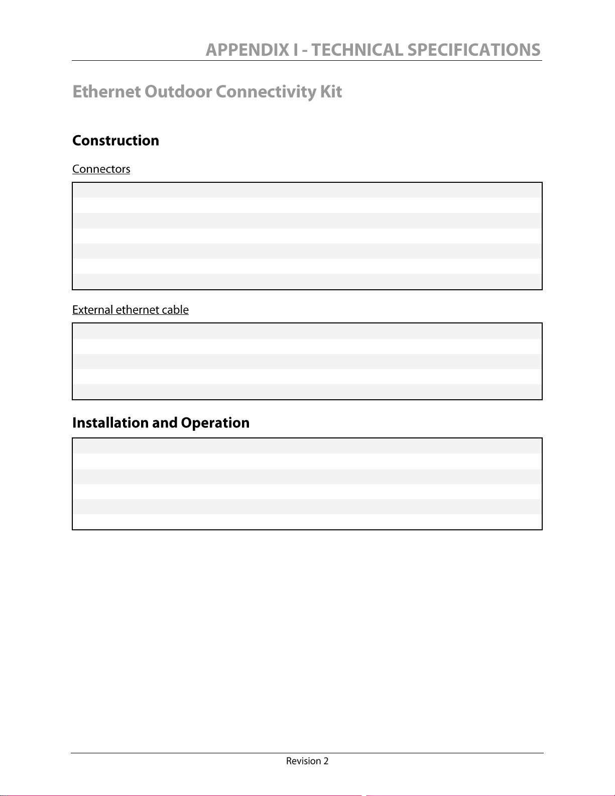
IP67 connection
Isolated to 1500 Vrms (on monitor side only)
Customizable cable length (up to 15 m [50 ft])
Oil and water resistant components
UV stabilized components
Category 5e components
Straight-through pair configuration
Datatuff® series cable for harsh environments
Cable jacket: Industrial grade PVC
100% Shielded (Bonded Bedfoil® and drain wire)
Conductors: 0.2 mm2 (AWG 24), solid bare copper
UL1581 rated (-40°C [-40°F]cold bend)
Operating temperature range: -40oC to 75C (-40°F to 167°F)
Installation temperature range: -25oC to 75C (-13°F to 167°F )
Min. bending radius 2.5 cm (1 inch)
Max. pulling tension 11.3 kg (25 lbs)
Immune to EMC
Fast plug-in and secure type of connectors
79
Page 90

 Loading...