

Morgan Olson 2016-2018 USPS 2 Ton Maintance Manual

UNITED STATES POSTAL SERVICE
2- TON DELIVERY TRUCK
SERVICE MAINTENANCE MANUAL
P/N 43004536
1801 S. Nottawa Street
Sturgis, MI 49091
Phone 800-233-4823
Fax (616-659-0499)
www.morganolson.com
www.morganolsonparts.com

2
Genuine OEM Parts 1.800.233.4823 www.morganolsonparts.com
3
USPS 2 Ton Delivery Vehicle 2016 - 2018 Models
CONFIDENTIAL NOT FOR DISTRIBUTION CONFIDENTIAL NOT FOR DISTRIBUTION
CONFIDENTIAL NOT FOR DISTRIBUTION CONFIDENTIAL NOT FOR DISTRIBUTION
NOTE: USE ONLY GENUINE MORGAN OLSON PARTS
USE OF NON OEM PARTS MAY VOID YOUR WARRANTY
AND/OR VIOLATE FMVSS STANDARDS
INTRODUCTION
This catalog has been prepared to assist the U.S.P.S. In the maintenance of the
Morgan Olson 2-Ton delivery truck. Inquiries on items found or not found in this
manual may be made through the address and or phone numbers listed below.
Morgan Olson
1801 S. Noawa
Sturgis, MI 49091
1-800-477-8287
(Customer Service/Fleet Warranty)
For Parts Ordering:
1-800-233-4823
1-616-659-0499 (Fax)
(Service Parts)
Contents
CONTENTS & INTRODUCTION 2-3
1. BODY TIE/DOWNS 4
2. DOORS
Side Doors 5-9
Bulkhead Door 10
Rear Door 11-17
3. GAS SPRING 18
4. HEATER
Motor, Fan & Plenum 19
Troubleshoong 20-31
5. HOOD 32
6. LAMPS 33
7. BODY PANEL REPLACEMENT AND RIVETS 34
8. WINDSHIELD
Windshield Removal and Installaon 35
9. WINDSHIELD WIPERS & MOTOR 36
10. LIFT-GATE 37-61
11. BACK-UP CAMERA & MONITOR 62-70
12. REAR VIEW MIRROR SYSTEMS 71-78
13. KEY-LESS ENTRY SYSTEM 79-84
14. VEHICLE JACKING POINTS 85
15. MAINTENANCE SCHEDULE (CHASSIS) 86-95
16. ELECTRICAL WIRING DIAGRAMS 96-115
Latest version of all documents available at;
www.morganolsonparts.com/t-usps_manuals.aspx
Access code: usps2016
4
Genuine OEM Parts 1.800.233.4823 www.morganolsonparts.com
5
USPS 2 Ton Delivery Vehicle 2016 - 2018 Models
CONFIDENTIAL NOT FOR DISTRIBUTION CONFIDENTIAL NOT FOR DISTRIBUTION
CONFIDENTIAL NOT FOR DISTRIBUTION CONFIDENTIAL NOT FOR DISTRIBUTION
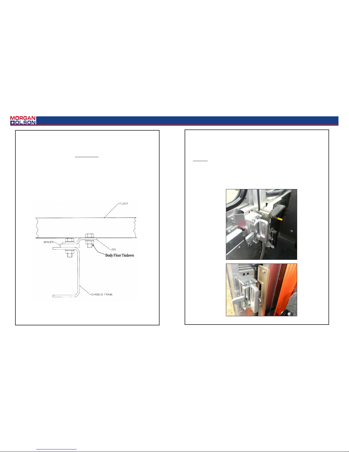
Body Tie/Downs
Tie/Down Check:
The oor of the truck is fastened to bolsters that extend the length of the oor.
The lower anges of the bolsters are mounted to the chassis frame rails.
Both sets of fasteners are torqued to specicaons.
All cab and body e/downs should be checked aer 3 months and annually.
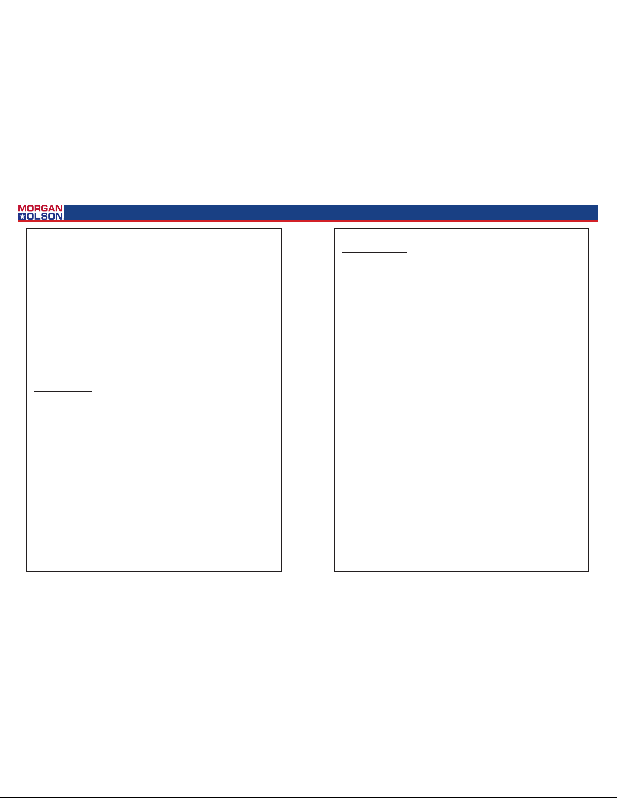
Side Door
Side Door
For smooth operaon the locking mechanism should be oiled every 3 months or as needed.
Grease should also be added at the contact points of locking mechanism arm and striker.
(At opened and closed posions.)
6
Genuine OEM Parts 1.800.233.4823 www.morganolsonparts.com
7
USPS 2 Ton Delivery Vehicle 2016 - 2018 Models
CONFIDENTIAL NOT FOR DISTRIBUTION CONFIDENTIAL NOT FOR DISTRIBUTION
CONFIDENTIAL NOT FOR DISTRIBUTION CONFIDENTIAL NOT FOR DISTRIBUTION
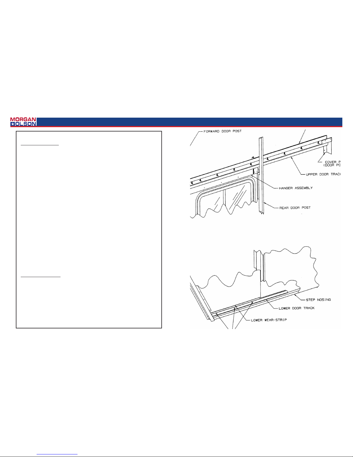
Side Door Removal:
1. Remove screws fastening down the lower door track but leave the track in posion.
2. Remove the Phillips screws and door pocket cover plate located in the upper rear corner
of the door pocket.
3. Remove the 4 fasteners and the door handles (inner and outer).
4. Using a socket wrench, remove the bolts fastening the door and hanger assembly.
5. To simplify door removal, remove the grab handle located forward of the door.
*Fold side view mirror back.
6. Holding the top of the door in posion, pull out on the boom front corner of the door
unl it clears the body of the truck. Then lt the top of the door down and out and remove the door.
Weather Seal Removal:
1. The forward and rear weather seals are installed simply by sliding into a mated part. To
remove simply pull straight out from the top of the door or door frame. Install by feeding
into the mated part and sliding into place.
Handle Mechanism Removal:
1. To remove the door handles simply remove the 4 mounng screws. Pay special aenon
to spacer locaons. You can then remove the inside and outside handles. Remember
when installing the handles, posion of the spacers idencal to the way they were at
removal.
Door Track (Upper) Removal:
1. The upper track is mounted to the header channel. Remove the nuts, and the track. Reinstall by reversing the removal sequence.
Wear Strip (Lower) Removal:
1. Remove side door.
2. Remove exisng rivets.
3. Replace wear strip and rivet in place.
Side Door Installaon:
1. Tilt the top of the door in place rst. Now posion the boom of the door into the lower
door track, which is in posion but not fastened down.
2. Put 1/8” shims between the lower door track and the wear strip.
3. Mount door to the hanger assembly.
4. Install door handles. See page 8.
5. Mount cover plate on upper rear door pocket.
6. Mount grab handle forward of door. *Re-adjust mirror.
7. For proper door adjustment see page 10.
8
Genuine OEM Parts 1.800.233.4823 www.morganolsonparts.com
9
USPS 2 Ton Delivery Vehicle 2016 - 2018 Models
CONFIDENTIAL NOT FOR DISTRIBUTION CONFIDENTIAL NOT FOR DISTRIBUTION
CONFIDENTIAL NOT FOR DISTRIBUTION CONFIDENTIAL NOT FOR DISTRIBUTION
Side Door Adjustment:
1. Loosen all nuts on the top of the sloed upper door track.
2. Loosen the 3 screws fastening down the lower door track.
3. The rear holes of the lower door track are oversized to allow for adjustment. Only the rear
poron of the track can be adjusted. The forward hole of the lower track is not oversized
because the door must retain its forward posion to ensure proper alignment when the
door is closed.
4. With the door closed and engaged in the forward strike, adjust the upper track for uniform lateral placement of the door in the forward post seal. Snug the forward bolt of the
upper door track.
5. With the door open and engaged in the rear strike, the rear poron of the upper and lower tracks can be adjusted laterally to ensure proper alignment with the rear striker.
6. When the door is posioned, ghten a few of the fasteners in the upper and lower tracks.
Operate the sliding door to ensure that it slides and latches properly.
7. When the door is operang properly, ghten all the remaining fasteners in the upper and
lower door tracks.
8. Replace any broken studs with .25 - 20x1.00 truss head screw.
9 See gure 1 on the following page.
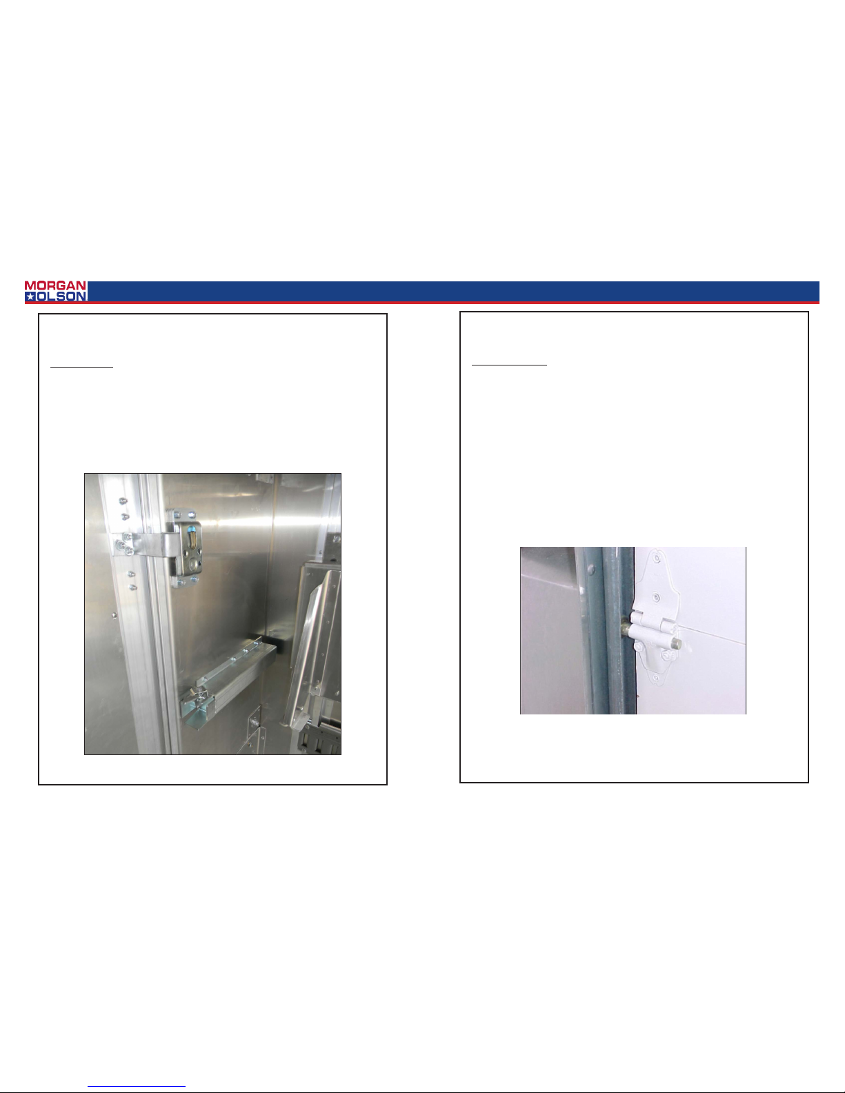
Door Latch Adjustment:
1. The door latches (strikers) and the mounng brackets provide for adjustment in a variety
of direcons.
2. Once the door has been adjusted to slide smoothly, then adjust the strikers for proper
latch operaon.
10
Genuine OEM Parts 1.800.233.4823 www.morganolsonparts.com
11
USPS 2 Ton Delivery Vehicle 2016 - 2018 Models
CONFIDENTIAL NOT FOR DISTRIBUTION CONFIDENTIAL NOT FOR DISTRIBUTION
CONFIDENTIAL NOT FOR DISTRIBUTION CONFIDENTIAL NOT FOR DISTRIBUTION
Rear Roll-Up Door:
1. Apply oil to the roller shas and locking mechanism every 6 months.
2. Perform a visual inspecon daily checking the liing mechanism cables and the door strap
for fraying.
3. Perform a visual inspecon monthly checking for damaged parts replace immediately to
prevent wear and fague on other components.
4. Refer to Trans global Door Company instrucons for proper rear door spring adjustment
and/or replacement.
Rear Door
Bulkhead Door:
*NOTE: Where grease is required use a lithium based.
1. The latch should be greased to prevent scking. Grease should be applied at contact
points of the latch and striker for smooth operaon. This should be done every 3 months.
Bulkhead Door
12
Genuine OEM Parts 1.800.233.4823 www.morganolsonparts.com
13
USPS 2 Ton Delivery Vehicle 2016 - 2018 Models
CONFIDENTIAL NOT FOR DISTRIBUTION CONFIDENTIAL NOT FOR DISTRIBUTION
CONFIDENTIAL NOT FOR DISTRIBUTION CONFIDENTIAL NOT FOR DISTRIBUTION
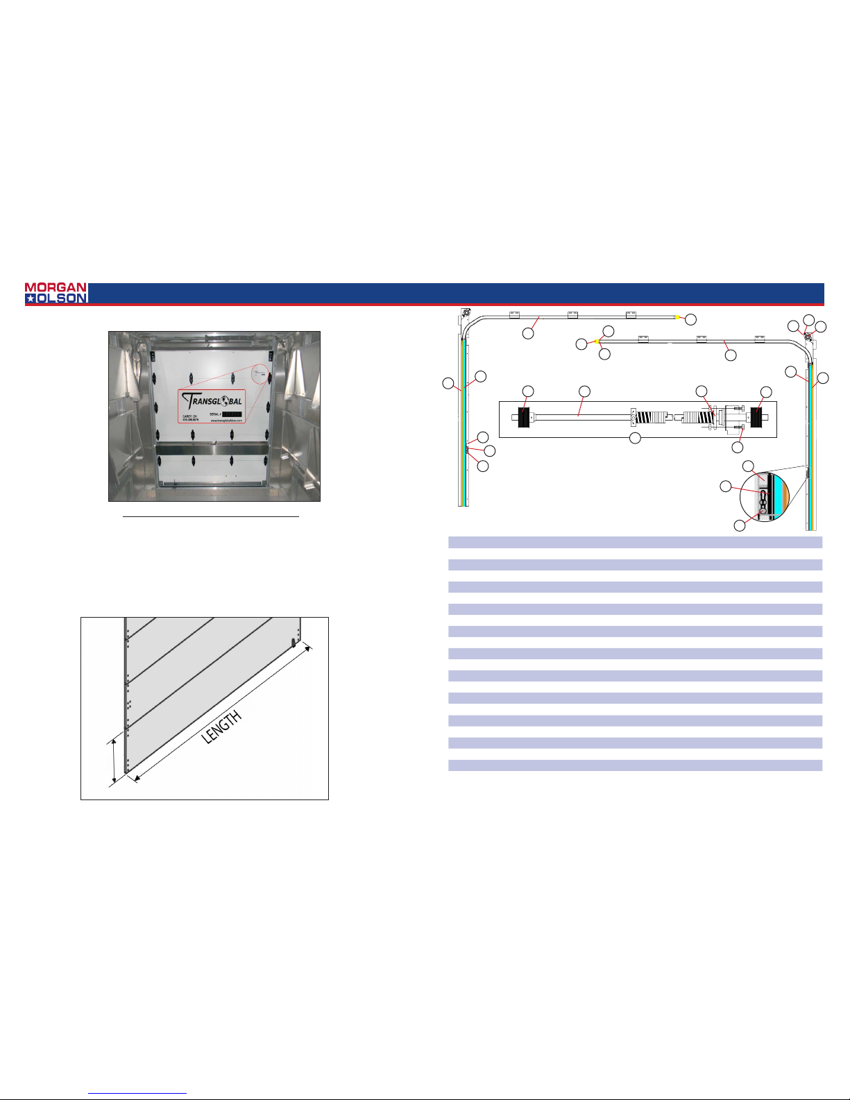
ROLL-UP DOOR SERIAL NUMBER LOCATION
WHEN ORDERING PARTS FOR ROLL-UP DOORS,
PLEASE PROVIDE THE FOLLOWING INFORMATION.
THE SERIAL NUMBER LOCATED ON THE INTERIOR TOP PANEL ROADSIDE EDGE.
THE LENGTH AND HEIGHT OF THE DOOR PANEL(S) TO BE ORDERED.
IN THE EVENT OF A DAMAGED, UN-READABLE OR MISSING SERIAL NUMBER,
PLEASE TRY TO PROVIDE THE COMPOSITION DETAILS OF THE DOOR PANEL.
(PLASTIC COATED, ALUMINUM CLAD, PLY WOOD, ETC.)
Rear Door
ITEM# PART# DESCRIPTION
1 47106737 BEARING ASSEMBLY
2 47106738 SIDE SEAL SNAP-IN STYLE 75.5”
3 47106739 1” HEAD PROTECTOR YELLOW
4 47106740 LOCK CATCH
5 47106741 LATCH GUARD ANGLE - LH (CS)
6 47106742 LATCH GUARD ANGLE - RH (RS)
7 47106743 5/16” X 1” HEX HEAD BOLT GRADE 5
8 47106744 5/16 KEP NUT
9 47106745 1/4 -20 X 1 3/4” HEX HEAD BOLT (25C175HCS5Z)
10 47106746 1/4” KEP NUT
11 47106747 VERTICAL TRACK ASSEMBLY - #47106270- CURBSIDE
12 47106748 VERTICAL TRACK ASSEMBLY - #47106270- ROADSIDE
13 47106749 HORIZONTAL TRACK ASSEMBLY- #47106270- CURBSIDE
14 47106750 HORIZONTAL TRACK ASSEMBLY- #47106271- ROADSIDE
Counterbalance Assembly
15 47106751 COUNTERBALANCE ASSEMBLY - #47106270
16 47106752 5/16” X 1” HEX HEAD BOLT GRADE 5
17 47106753 CABLE DRUM LH
18 47106754 CABLE DRUM RH
19 47106755 COUNTERBALANCE SHAFT - 68.75”
21 47106737 BEARING ASSEMBLY
17
5
10
4
6
2
11
8
7
1
13
9
3
10
14
12
2
4
10
16
18
21
19
15
3
ROLL UP DOOR
14
Genuine OEM Parts 1.800.233.4823 www.morganolsonparts.com
15
USPS 2 Ton Delivery Vehicle 2016 - 2018 Models
CONFIDENTIAL NOT FOR DISTRIBUTION CONFIDENTIAL NOT FOR DISTRIBUTION
CONFIDENTIAL NOT FOR DISTRIBUTION CONFIDENTIAL NOT FOR DISTRIBUTION
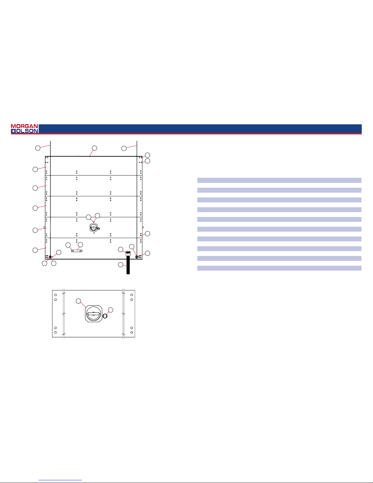
ROLL UP DOOR ROLL UP DOOR
11
18
ITEM# PART# DESCRIPTION
1 47106701 LIFT HANDLE - WHITE
2 47106703 CABLE ANCHOR BRACKET - WHITE
3 47106706 1/4” X 1” CABLE ANCHOR PIN
4 47106719 3/32” X 1” COTTER PIN
5 47106709 BEST CYLINDER LOCK AND MODIFIED RING 6.25MM
6 47106722 1/4”-20 X 1” CARRIAGE BOLT - STAINLESS STEEL
7 47106723 1/4” NYLOK NUT
8 47106724 1/4” X 5/8” SS SEMI TUBULAR RIVET
9 47106725 1/4” X 3/4” SS SEMI TUBULAR RIVET
10 47106726 1/4” X 7/8” SS SEMI TUBULAR RIVET
11 47106727 CABLE 95” 7 X 19 SS 1/4 METAL EYE (EACH)
12 47106728 12” PULL STRAP - LOOPED W/ BLACK RETAINER
13 47106729 D-RING HANDLE - 2 PT LOCK
14 47106732 .25” COMPOSITE TOP PANEL- COMPLETE- 13.5” X 68.75” W/ SEAL
15 47106733 .25” COMPOSITE INTERMEDIATE PANEL - 15” X 68.75”
16 47106735 .25” COMPOSITE 2PT LOCK PANEL- COMPLETE 15” X 68.75”
17 47106734 .25” COMPOSITE BOTTOM PANEL -COMPLETE 15” X 68.75”
18 47106736 TOP PANEL SEAL ASSEMBLY - 68.75”
6
13
5
8
12
10
1
8
3
4
17
16
15
15
14
11
9
8
2
8
2
7
16
Genuine OEM Parts 1.800.233.4823 www.morganolsonparts.com
17
USPS 2 Ton Delivery Vehicle 2016 - 2018 Models
CONFIDENTIAL NOT FOR DISTRIBUTION CONFIDENTIAL NOT FOR DISTRIBUTION
CONFIDENTIAL NOT FOR DISTRIBUTION CONFIDENTIAL NOT FOR DISTRIBUTION
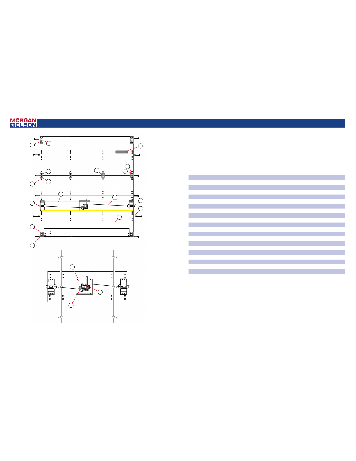
ROLL UP DOOR
6
9
10
17
1
19
3
4
20
2
14
13
5
18
8
7
13
16
15
11
ITEM# PART# DESCRIPTION
1 47106700 ROLLER HINGE COVER
2 47106702 CABLE ASSY. 29.75” WITH (2) STOPS & WASHER (EACH) 2
3 47106704 ROLLER CLAMP, 3 HOLE ROLLER CLAMP FOR 1” ROLLERS
4 47106705 3 STUD BOTTOM FIXTURE ASSEMBLY -COMPLETE
5 47106707 1” STEEL ROLLER
6 47106708 TOP CAM CATCH
7 47106710 TOP CLOSURE ASSEMBLY COMPLETE
8 47106711 TOP CLOSURE SLIDE ONLY
9 47106712 CENTER CONTROL COMPLETE
10 47106714 LATCH BASE CENTER - .80” OFF, D-RING,BEST CYLINDER,
11 47106715 ALUMINUM CABLE COVER - 68.375” LENGTH - 7.5MM COMP,
12 47106716 TWO POINT END LATCH ASSEMBLY- CURBSIDE
13 47106717 TWO POINT END LATCH ASSEMBLY- ROADSIDE
14 47106718 SPACER WASHER
15 47106720 BUCK RIVET - 11/16”
16 47106721 BUCK RIVET - 13/16”
17 47106730 1207 HEAVY DUTY
18 47106731 CENTER HINGE-HEAVY DUTY
19 47106723 1/4” NYLOK NUT
20 N/A IDENTIFICATION PLATE S/N
NS 47106756 PLASTIC LATCH GUARD
ROLL UP DOOR
18
Genuine OEM Parts 1.800.233.4823 www.morganolsonparts.com
19
USPS 2 Ton Delivery Vehicle 2016 - 2018 Models
CONFIDENTIAL NOT FOR DISTRIBUTION CONFIDENTIAL NOT FOR DISTRIBUTION
CONFIDENTIAL NOT FOR DISTRIBUTION CONFIDENTIAL NOT FOR DISTRIBUTION
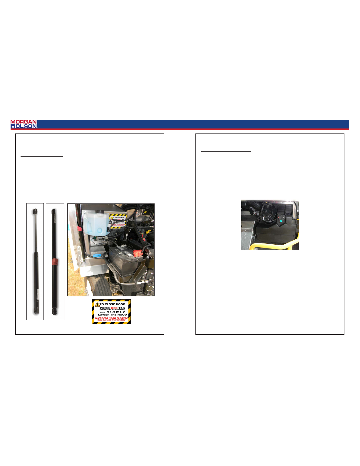
Gas Spring Replacement:
1. With the hood safely propped, remove the upper and lower retainer clips. Once the clips
have been removed a slight tap will remove the gas spring from the ball studs.
2. For safety reasons, when replacing the gas springs use only Morgan Olson OEM replacement parts.
Gas Spring
Heater
Motor and Fan Replacement:
1. The heater is mounted to the right hand dash panel.
2. With the power to the motor o, disconnect the motor leads.
3. Remove motor mounng screws. Remove the motor and the impeller wheel.
4. Take out the set screw to remove the impeller wheel (squirrel cage).
5. For installaon, reverse the sequence.
Plenum Replacement:
1. Detach air inlet hose from plenum.
2. Disconnect wiring harness at heater box and instrument panel harness.
3. Remove fasteners from plenum diuser (located on top of the windshield rail).
4. Remove the fasteners located on top of the windshield rail.
5. Installaon sequence is opposite of removal.
Plenum
20
Genuine OEM Parts 1.800.233.4823 www.morganolsonparts.com
21
USPS 2 Ton Delivery Vehicle 2016 - 2018 Models
CONFIDENTIAL NOT FOR DISTRIBUTION CONFIDENTIAL NOT FOR DISTRIBUTION
CONFIDENTIAL NOT FOR DISTRIBUTION CONFIDENTIAL NOT FOR DISTRIBUTION
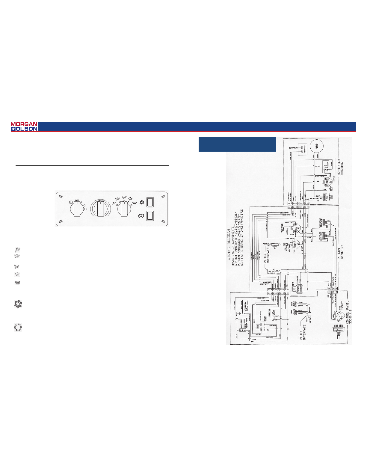
BLOWER CONTROL
The BLOWER CONTROL provides three choices of air velocity in every operating mode. When the blower switch knob is rotated fully counterclockwise (with the knob indicator pointing
straight up) the blower is turned OFF. Rotating the knob clockwise will progressively increase the air velocity.
TEMPERATURE
CONTROL
The TEMPERATURE CONTROL
KNOB controls the discharge air temperature in
all operating modes. Turning the knob to the right
(red zone) increases tem-
to the left (blue zone) decreases air temperature. Temperature control is achieved through the regulation of engine coolant through
the heater coil.
MODE SELECTION SWITCH
When this mode is selected, all air is discharged through the dash louvers
.
With this setting, air is discharged through the dash louvers and onto the floorboard. This is the
ideal mode for rapid warm-up in cold weather
.
This mode will direct all air to the floorboard. This mode is most frequently selected when heating
is required.
When this mode is selected, air is discharged onto the floorboard and onto the wind-
shield.
This mode will direct most of the air to the windshield and provides for rapid defrosting of
the outside of the windshield and defogging of the inside surface. A reduced volume of air is provided for
floor heating.
A/C CONTROL
The blue rocker switch will engage the A/C system compressor when the upper edge of the switch is
pressed. Pressing the lower side of the switch will turn the A/C compressor off.
AIR SOURCE CONTROL
The green rocker switch permits the driver to re-circulate cabin air or introduce outside air into the
HVAC system. Pressing the upper edge of the green switch will block outside air and permit the re recirculation of inside air. Pressing the lower edge of the switch will introduce outside air.
22
Genuine OEM Parts 1.800.233.4823 www.morganolsonparts.com
23
USPS 2 Ton Delivery Vehicle 2016 - 2018 Models
CONFIDENTIAL NOT FOR DISTRIBUTION CONFIDENTIAL NOT FOR DISTRIBUTION
CONFIDENTIAL NOT FOR DISTRIBUTION CONFIDENTIAL NOT FOR DISTRIBUTION
, No air flow, blower does not operate
POSSIBLE CAUSE #1
~ Faulty Blower Motor
CORRECTIVE ACTION ~ With ignition turned ON, unplu g the 2-pin connector at the blower motor. Check the orange
wire for +12 volts and the white wire for a f ully grounded circuit. If power is present and the circuit grounded, remove the
motor and wheel from the blower housing. Ins pect for any evidence of entrapped debris or a broken blower wheel that
might have prevented rotation. If no such e vidence exists, replace the blower motor.
POSSIBLE CAUSE #2
~ Blown fuse due to short in wire harness
CORRECTIVE ACTION ~ Refer to the HVAC Wiring Diagram and th e Chassis Manufacturer’s wiring information.
Trace the entire HVAC wiring for an electrica l short. Replace or repair as required.
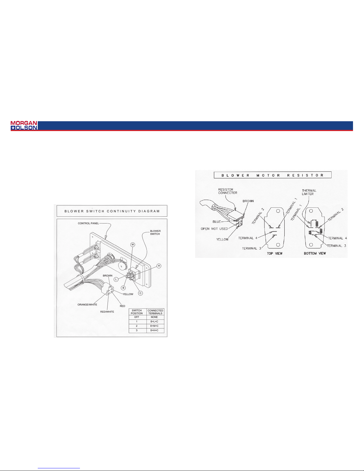
POSSIBLE CAUSE #3
~ Defective Blower Switch
CORRECTIVE ACTION ~
Refer to the Blower Switch
Continuity Diagram and
check the blower switch for
continuity through the switch
in all four switch positions.
Replace the blower switch as
required.
, Blower operates, but not in all blower switch settings
POSSIBLE CAUSE #1
~ Blower resistor failure.
CORRECTIVE ACTION ~ If the blower operates only on the h ighest blower speed (blower switch rotated fully clockwise), the blower resistor has, most likely, failed. [Hin t: The resistor is bypassed when the highest blower speed is selected.] Refer to the Blower Motor Resistor -wire connector from the resistor. Check
for electrical continuity between terminal 1 and 2. If an open circuit exists between 1 and 2, the thermal limiter has blown
and it will be necessary to replace the resis tor. [Note: A failed resistor is often the r esults of a problem with the blower
motor. Make sure that the blower motor is fully operable and is not bound in any sort of way by a broken blower wheel
or entrapped debris within the blower hous ing.]
POSSIBLE CAUSE #2
~ High-blower relay failure
CORRECTIVE ACTION ~ If the blower operates in all s peed selections except for the highest selection there is a possibility that the high-blower relay has failed. [Note: T he high-blower relay is activated when the h ighest blower speed is
selected. The relay extends the life of the blower switch and insures the highest voltage for the motor.] Remove the relay and test for an open circuit across term inals 85 and 86. If the circuit is open, replace the relay.
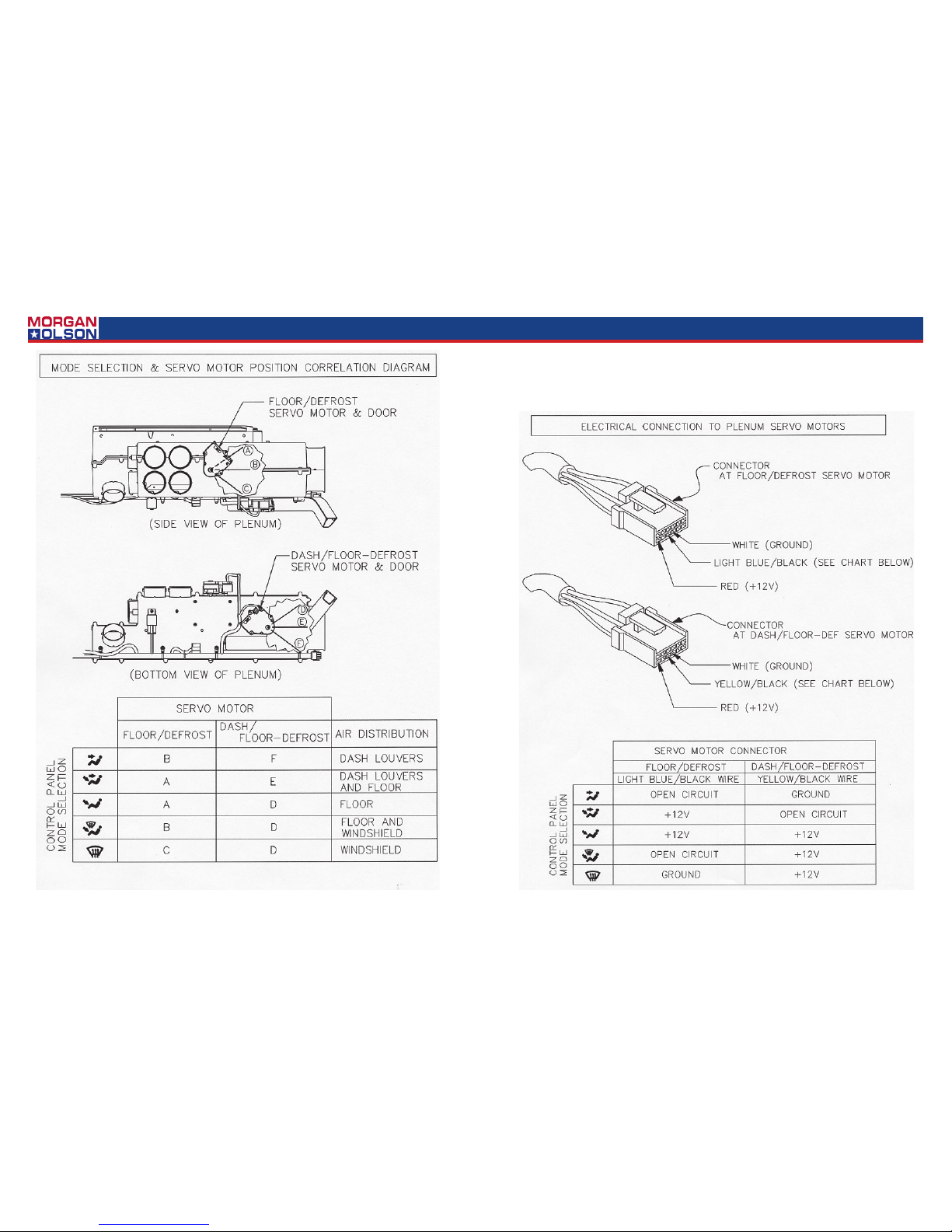
~ Air does not flow from the selected outlets
POSSIBLE CAUSE #1
~ Plenum directional doors obstructed
CORRECTIVE ACTION ~ Examine the air distribution Pl enum for any possible obstruction that m ight have become entrapped internally. Refer to the Mode Selection & Servo Motor Position Correlation Diagram for the position of each
of the doors in every mode selection. The o utput shafts of the servo motors can be observed, externally, as they move
through their approximate 100 degrees of travel. Also, the doors can be physically touched by removing the 5” flexible
inlet duct and reaching into the plenum ’s air intake. If a physical obstruction is suspected, it may be necessary to remove the plenum. [Note: Access to the plenum ’s mounting hardware will require removal of the defroster ducts from
atop the dash.]
24
Genuine OEM Parts 1.800.233.4823 www.morganolsonparts.com
25
USPS 2 Ton Delivery Vehicle 2016 - 2018 Models
CONFIDENTIAL NOT FOR DISTRIBUTION CONFIDENTIAL NOT FOR DISTRIBUTION
CONFIDENTIAL NOT FOR DISTRIBUTION CONFIDENTIAL NOT FOR DISTRIBUTION
POSSIBLE CAUSE #2
~ Servo motor failure
CORRECTIVE ACTION ~ If servo motor failure is suspected, the first step is to confirm that the electrical connections at
the servo motors are delivering the correct s ignal to the motors. With the ignition switch turned to Accessory, unplug
each of the servo connectors and test acc ording to the information in the Electrical Connection To Plenum Servo Mo-
tors Diagram. If the electrical check is in agreem ent with the Diagram and if the directional doors are not obstructed,
the likely problem is a failed servo motor. Re place servo motor as required.

26
Genuine OEM Parts 1.800.233.4823 www.morganolsonparts.com
27
USPS 2 Ton Delivery Vehicle 2016 - 2018 Models
CONFIDENTIAL NOT FOR DISTRIBUTION CONFIDENTIAL NOT FOR DISTRIBUTION
CONFIDENTIAL NOT FOR DISTRIBUTION CONFIDENTIAL NOT FOR DISTRIBUTION
POSSIBLE CAUSE #3
~ Control Panel Selector Switch is def ective
CORRECTIVE ACTION ~ With the ignition turned to Acc essory, unplug each of the connectors fr om the Plenum servo
motors and test according to the inform ation in the Electrical Connection To Plenum Servo Motors Diagram. If the
test fails to find agreement with the Diag ram there is a good possibility that the M ode Selection Switch at the control
panel is defective. Replace the Mode Sel ection Switch.
Air temperature cannot be controlled
POSSIBLE CAUSE #1
~ Water valve not operating
CORRECTIVE ACTION ~ Valve may
not be receiving a signal from control
panel, or valve is defective. Disconnect the electrical connector from the
valve. With the ignition switch turned
to Accessory, check for the presence
of 12 volts between the red wire (+12
V) and the white wire (ground) as noted in the Water Valve Electrical Dia-
gram. The yellow/red signal wire will
provide +12 V (full cold position) dropping to zero volts (full hot position) as
the temperature control knob is rotated
clockwise. If the condition at the connector is in agreement with the Dia-
gram, proceed as follows:
Step 1 Disconnect the water valve
from the 5/8” heater hoses,
Step 2 Carefully inspect the four
small terminal pins on the motor, mak e
sure that they are not damaged,
Step 2 Reconnect the valve to the
electrical connector,
Step 3 Rotate the Temperature Control Knob and watch for any response
from the valve,
Step 4 If no valve rotation is observed, replace the valve.
POSSIBLE CAUSE #2
~ Water valve not electrically connected
CORRECTIVE ACTION ~ Disconnect the electrical connec tor from the valve. With the ignition s witch turned to Acces-
sory, check for the presence of 12 volts bet ween the red wire (+12 V) and the white wire (ground) as noted in the W ater
Valve Electrical Diagram. The yellow/red s ignal wire will provide +12 V (full cold pos ition) dropping to zero volts (full hot
position) as the temperature control knob is rotated clockwise. If none of these conditions exist, r efer to the Wiring Dia-
gram and examine the system’s wire har ness for any loss of continuity. Repair a s required.
, A/C system not providing cool air
POSSIBLE CAUSE #1
~ Loss of refrigerant
CORRECTIVE ACTION ~ Verify the presence of 1.75 poun ds of refrigerant R134a. If the AC system is either partially
low, or completely empty, a search wil l be required for leakage. Replace and re pair as required.
POSSIBLE CAUSE #2
~ Compressor not engaged
CORRECTIVE ACTION ~ Confirm that the system is fully char ged. With the ignition switch turned to Accessory, the
blower switch turned to the highest speed a nd the AC (blue) rocker switch engaged, pr oceed as follows:
Step 1: Check for the presence of 12 volts at the com pressor. If yes, make certain that the compressor clutch is fully
grounded. If the ground circuit is intact, th e compressor clutch has, most likely, failed and requires replacement.
Step 2: If no voltage is present at the compres sor clutch, refer to the Wiring Diagram and check for voltage at each of
the system pressure switches.[Note: The low pres sure switch is located on the suction hose n ear the firewall and opens
on a pressure drop to 8 psi. The binar y (high/low) pressure switch is located on t he liquid hose near the receiver/drier
and opens on a pressure rise to approxim ately 400 psi and a pressure drop to 28 ps i.] With the system fully charged,
there should be continuity through both s witches. Replace as required.
Step 3: If no voltage is present at the pressure s witches, check for voltage at the ther mostat (located externally on the
HVAC housing). Assuming that the evap orator coil is fully warmed to ambient conditions, the thermostat should be a
closed circuit. [Note: The thermostat circuit opens when the evaporator coil surf ace temperature drops below 32 de-
circuit, replacement is required. Therm ostat replacement requires the complete removal and disassembly of the HVAC
housing. When replacing thermostat, tak e special care to not kink the capillary tube. Also, install the new capillar y tube
in the same location as the original.
POSSIBLE CAUSE #3
~ Perceived lack of cooling due to extrem e conditions
CORRECTIVE ACTION ~ Note that extremely high hum idity can reduce the effectiveness of the evaporator. The Ambient Temperature vs. Relative Humidit y Chart (below) illustrates how very hig h humidity can raise the louver tem-
peratures. This test is best performed with the doors and windows open, the blower tur ned to the highest speed and the
AC system fully engaged. Run the engine at 1500 rpm and allow time for the system to stabilize. Measure the discharge air temperature at one of the dash lo uvers and compare to the Chart.
28
Genuine OEM Parts 1.800.233.4823 www.morganolsonparts.com
29
USPS 2 Ton Delivery Vehicle 2016 - 2018 Models
CONFIDENTIAL NOT FOR DISTRIBUTION CONFIDENTIAL NOT FOR DISTRIBUTION
CONFIDENTIAL NOT FOR DISTRIBUTION CONFIDENTIAL NOT FOR DISTRIBUTION
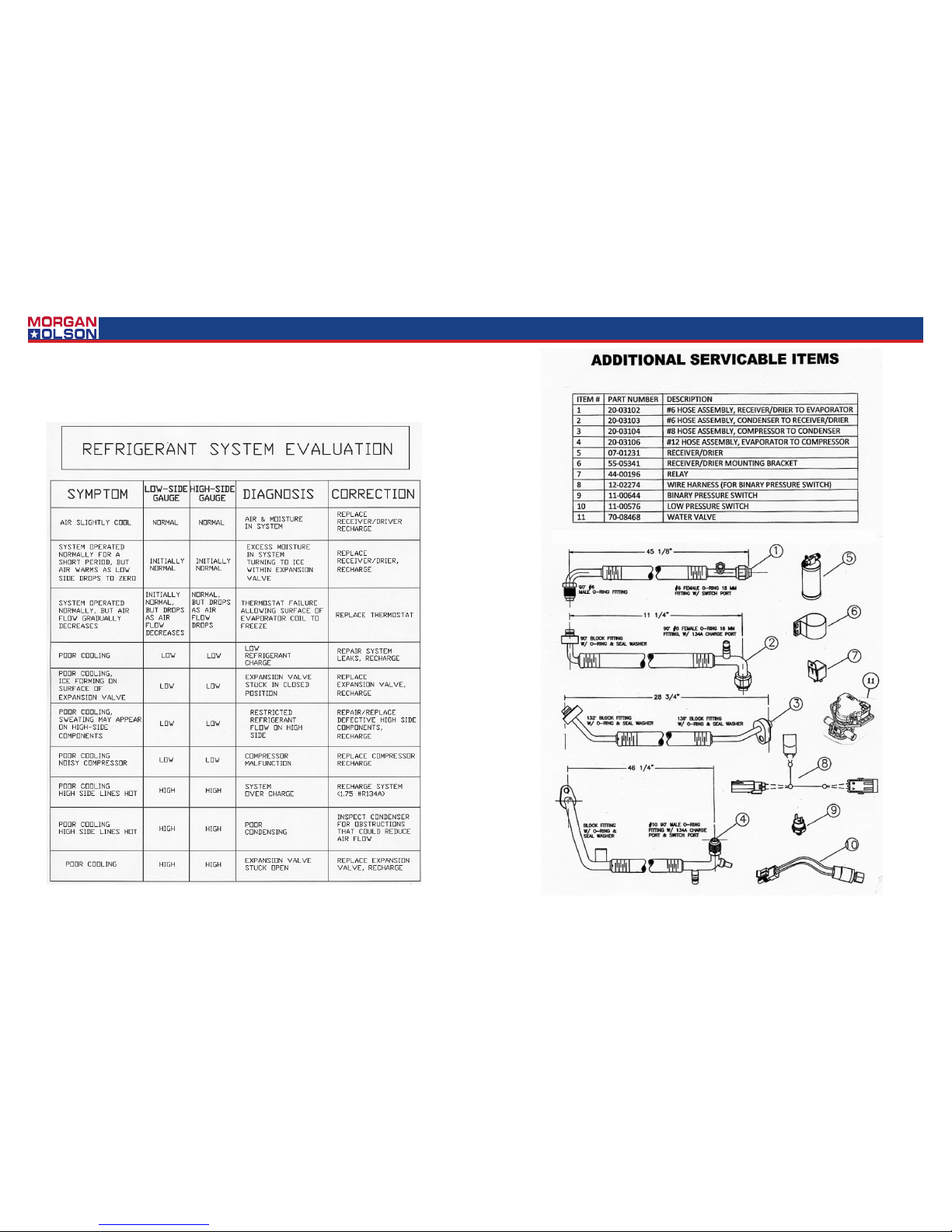
Consult the following Refrigerant System Evaluation chart (below) for a list of refrigerant related symptoms and the ir
recommended resolution:
30
Genuine OEM Parts 1.800.233.4823 www.morganolsonparts.com
31
USPS 2 Ton Delivery Vehicle 2016 - 2018 Models
CONFIDENTIAL NOT FOR DISTRIBUTION CONFIDENTIAL NOT FOR DISTRIBUTION
CONFIDENTIAL NOT FOR DISTRIBUTION CONFIDENTIAL NOT FOR DISTRIBUTION
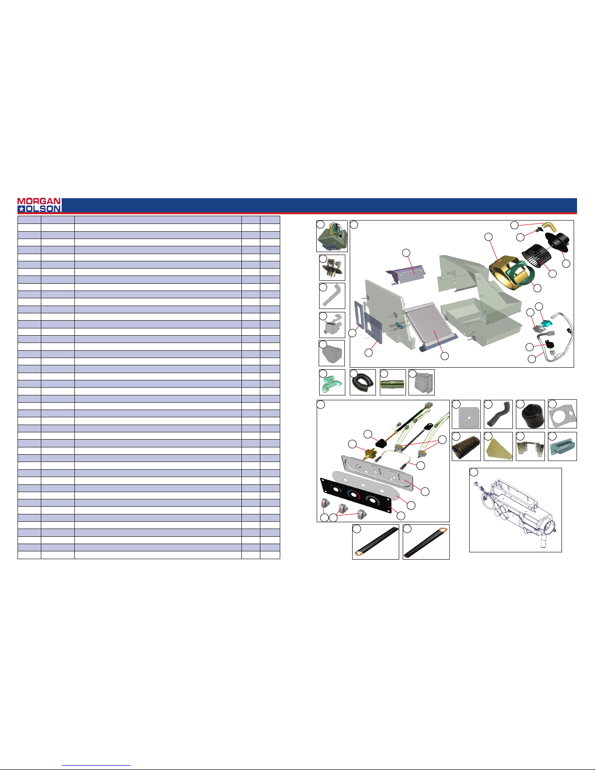
ITEM # PART # DESCRIPTION QTY UNIT
1 555001107 HEATER CORE ASSEMBLY 1 EA
2 470 08760 HEATER COIL W/GASKET & CLAMP 1 EA
3 470 08753 DOOR W/SEA L 1 EA
4 470 08754 BLOWER HOUSING 1 EA
5 470 08755 BLOWER ADAPTER 1 EA
6 470 08732 RESISTE R CAGE 1 EA
7 470 08357 RESISTER 1 EA
8 470 08756 BLOWER M OTOR 1 EA
9 470 08757 BLOWER WHEEL 1 EA
10 47008730 VENT TUB E 1 EA
11 470 08731 VENT TUBE ADAPTER 1 EA
12 470 08716 R EL AY 1 EA
13 4700 8758 H ARNESS 1 EA
14 4700 8580 FORMED HEATER HOSE 2 EA
15 555002053 VA LVE WAT ER 1 EA
16 10508 0401 PL ATE MOUNTING FOOT DUMP AL .07X4.25X5.53 1 EA
17 09 0080 401 DUCT F T DUMP SPECIAL 1 EA
18 21-01201 GASKET - PART OF HEATER ASSEMBLY 1 EA
19 21- 01202 GASKET - PART OF HEATER ASSEMBLY 1 EA
20 555001416 CONT ROL PANEL ASSEMBLY 1 EA
21 470 08706 KNOB 2 EA
22 470 08735 KNOB 1 EA
23 4700 8707 D ECAL 1 EA
24 4700 8708 LIGHT PANEL 1 EA
25 4700 8709 CONTROL SUB PANEL 1 EA
26 4700 8700 B LOWER SWITCH 1 EA
27 47 008710 POTENTIOMETER SWITCH 2 EA
28 4 700 8711 HARNESS ILLUMINATION W/BULBS 1 EA
29 470 08712 HARNESS BLOWER MOTOR 1 EA
30 555001721 DEFROST DUCT CURBSID E METAL 1 EA
31 555001722 DEFROST DUCT ROADSI DE METAL 1 EA
32 093080400 HOLD DOWN PL ATE DEFROSTER DUCTS 4 EA
33 555001524 HOS E DEFROSTER 2.5X30 1 EA
34 555001525 HOSE DEFROSTER 2.5X38 (2x DEFROST ER / 1xFOOT DU MP) 3 EA
35 555002003 COLL AR FRESH AIR INTAKE 1 EA
36 555001715 LOUVER BA LL 6 EA
37 555002007 PLENUM FRESH AIR SIDE WALL (DRAIN HOS E - 555002008) 1 EA
38 10 70274 05 BRACKET HEATER VENT 1 EA
39 555001533 HOS E BLOWER HEATER/DEFROSTER 5”X 7.5” 1 EA
40 00 5780402 MOUNTING PLATE 1 EA
41 002080400 BR ACKET HEATER CONTROL AL .102X3X11.67 1 EA
42 5550 01321 DUC T HVAC 1 EA
43 555001523 HOS E DEFROSTER 2.5X16 1 EA
44 47008017 CONNECTOR STRAIGHT .62ID BLACK NYLON 2 EA
NS 555002164 CAP DEFROSTER PORT 2.5IN DIA ROUND 2 EA
10
11
4
3
1
19
18
2
12
13
6
7
5
9
8
7
14
1
17
21
23
24
25
26
27
28
29
30
31
32
36
42
38
39
40 41
22
33
35
20
16
15
43 44 37
32
Genuine OEM Parts 1.800.233.4823 www.morganolsonparts.com
33
USPS 2 Ton Delivery Vehicle 2016 - 2018 Models
CONFIDENTIAL NOT FOR DISTRIBUTION CONFIDENTIAL NOT FOR DISTRIBUTION
CONFIDENTIAL NOT FOR DISTRIBUTION CONFIDENTIAL NOT FOR DISTRIBUTION
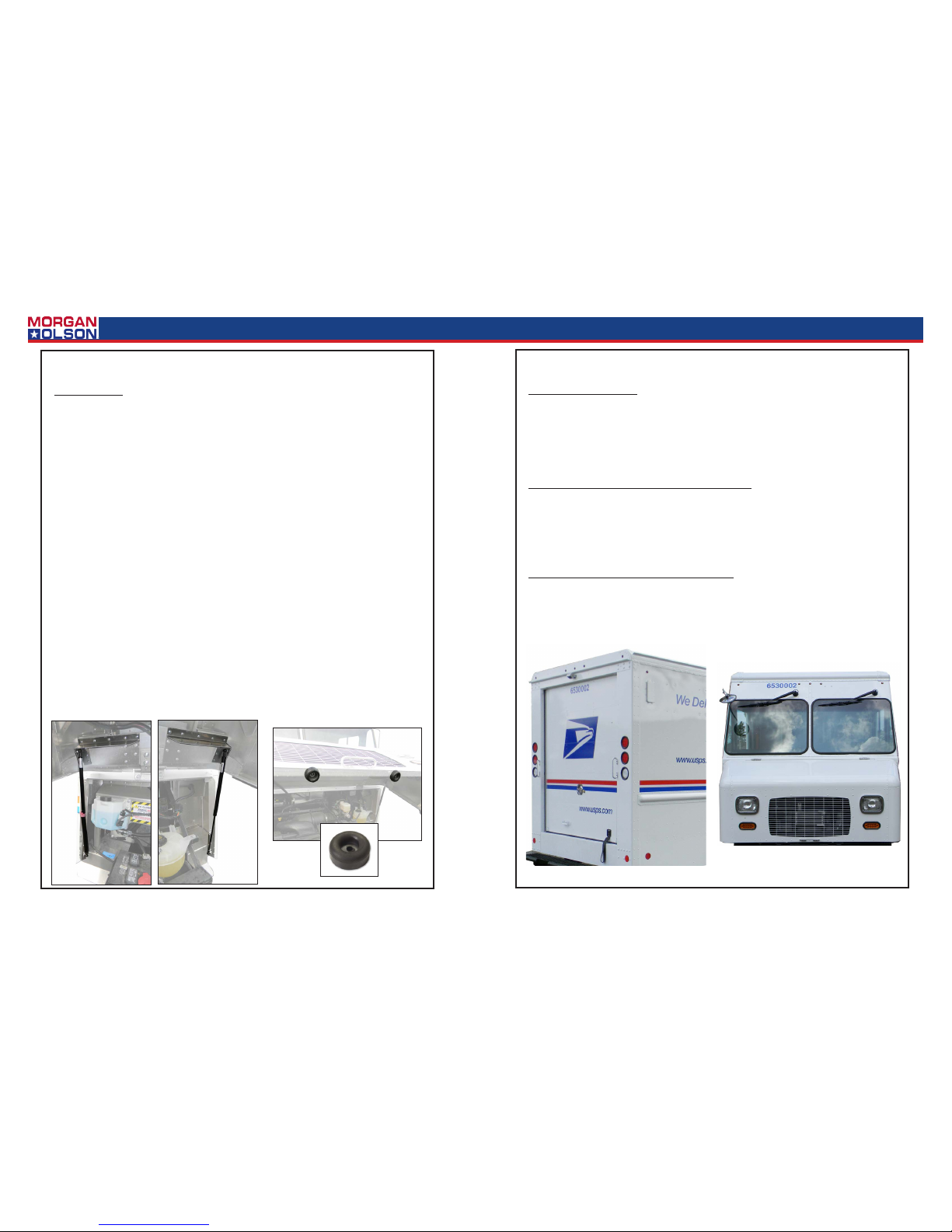
Hood Removal:
1. For removal of the gas springs. See page 14.
2. Disconnect wire harness plug connecons.
3. Remove the 4 bolts tying the le and right hinge assemblies to the body of the truck.
4. Disconnect hood prop.
5. At this point the hood can be removed.
Hood Installaon:
1. Before installaon fasten hinge assemblies to hood assembly. Now using the original 4
fasteners install the completed assembly.
2. For installaon of the gas springs, see page 14.
3. Reconnect all wiring.
4. Reconnect hood prop.
Hinge Replacement:
1. To replace hood hinge, remove three bolts aached to hood assembly.
2. Remove two bolts aached to windshield rail.
3. Slide hinge out to the side of the truck.
4. To replace hinge, install in reverse order.
Hood Stop Adjustment:
1. The stops that support the hood should be adjusted if the hood ever comes into contact
with the cab skirts. The stop bracket is sloed to allow for vercal adjustment. Adjust
brackets so that hood seats evenly and does not come into contact with cab skirts.
HOOD
Headlight Replacement:
1. Remove screws and trim from around headlight.
2. Remove headlight.
3. Remove wiring plug from back of headlight.
4. Replace headlight.
5. For installaon reverse removal sequence.
Tail, Turn Backup and Marker Lamp Replacement:
1. Push tail, turn back-up lamp into rubber grommet and use a small at head screw driver
and pry lamp from rubber grommet.
2. Remove wiring plug from back of lamp.
3. Install new lamp by reconnecng wiring plug to new lamp and pushing lamp into rubber
grommet unl properly seated.
Clearance Marker and ICC Light Replacement:
1. From inside, unplug the lamp, push lamp out of the grommet. To replace, from the outside push the lamp into grommet. Some lubricaon helps installaon. Install so the marking is towards the top. Hook up wiring taking care to match the polarity.
LAMPS
34
Genuine OEM Parts 1.800.233.4823 www.morganolsonparts.com
35
USPS 2 Ton Delivery Vehicle 2016 - 2018 Models
CONFIDENTIAL NOT FOR DISTRIBUTION CONFIDENTIAL NOT FOR DISTRIBUTION
CONFIDENTIAL NOT FOR DISTRIBUTION CONFIDENTIAL NOT FOR DISTRIBUTION
Body Panel Replacement:
1. When replacing exterior body panels, remove rivets following procedures outlined below.
2. Apply sealant to new panel as required.
3. Install new panel in reverse order.
Removing A Rivet:
1. When removing an exisng rivet, place the drill bit on the small dot in the center of the
rivet head. Twist the drill chuck by hand to enlarge the small dot. This will prevent the drill
from slipping.
2. *Never drill completely through the rivet or you risk enlarging the hole which can weaken
the bond when re-fastened. Drill into the center of the rivet head. With drill turned o
but sll in place, move it horizontally and vercally unl the head of the rivet comes o.
Use an awl and a mallet to tap the rivet shank out.
3. If you accidentally drill through the material, see the following instrucons.
Re-Riveng:
1. When replacing new panels, use .19 diameter rivets. The correct length rivet will measure
.25-.38 beyond the material being joined. (See diagram below)
2. When ever rivets are removed there is always some enlargement to the hole. To ensure
the strength of the new bond, follow these steps.
3. Drill the hole out to .25” diameter. If the hole is already .25” diameter then drill it out to
.28” diameter and use a .25” bolt and nut, otherwise connue to the next step.
4. Rivet the parts using a .25” rivet. The correct length rivet will measure .25-.38 beyond the
material being joined.
NOTE: As the vehicle ages, it is not uncommon for some rivets to loosen. This can oen
be detected by a black ring (aluminum oxide) around the head of the rivet. If this happens
replace the rivet. See Re-Riveng.
BODY PANEL REPLACEMENTS & RIVETS
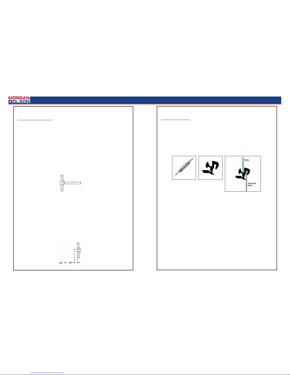
Windshield Removal:
1. Special tools are required for windshield removal. Glass and Bead Tools.
2. A soap and water soluon should be applied around the rubber seal. This will allow the
tools to move smoothly when in contact with the rubber seal.
3. Using the glass tool pry between the windshield and the rubber seal. This will enable
you to pry the glass from the seal. Leaving the tool in posion work your way around the
glass. Pushing the top corners of the windshield from inside the truck will get the removal
process started.
NOTE: For safety reasons this task should be performed by two people.
Windshield Installaon:
1. Special tools are required for windshield removal. Glass and Bead Tools.
2. Insert rubber seal into window frame.
3. A soap and water soluon should be applied around the rubber seal. This will allow the
tools to move smoothly when in contact with the rubber seal.
4. Posion the boom of the windshield in place rst. Using the glass tool pry the lip on the
seal out to allow the windshield to seat in the seal properly. Work your way around the
window unl it is seated properly.
5. Do this around the whole windshield unl the windshield seats properly in the frame.
WINDSHIELD REPLACEMENT
 Loading...