

Morgana Plockmatic BM 60, Plockmatic BM 61 Service Manual

Provided By
http://www.MyBinding.com
http://www.MyBindingBlog.com
Plockmatic BM 60/61
2006 Bookletmaker
Service Manual
BOOKLET MAKER BM 60/61
SERVICE MANUAL
3 October 2006
Part no. 60243


3
TABLE OF CONTENTS
1. INTRODUCTION
1.1 GENERAL INFORMATION ...........................................................................4
1.2 PLOCKMATIC CHISEL POINT STAPLES .................................................... 4
1.3 SPECIAL TOOLS ..........................................................................................4
2. COVER REMOVAL INSTRUCTION (CRI)
CRI 2.1 FRONT AND REAR COVER ................................................................ 5
CRI 2.2 INFEED AND OUTFEED COVER ........................................................6
3. REPAIRS/ADJUSTMENTS (REP)
REP 3.1 PARALLELISM FOLD KNIFE - ANVIL BAR .........................................7
REP 3.2 ADJUSTMENT OF SIDE GUIDES BM 60 ........................................... 8
REP 3.3 ADJUSTMENT OF SIDE GUIDES BM 61 ............................................ 9
REP 3.4 ADJUSTMENT OF SIDE JOGGER MOVEMENT BM 61 ................... 10
REP 3.5 PARALLELISM STAPLE STOP - ANVILS ..........................................11
REP 3.6 PARALLELISM FOLD STOP - FOLD KNIFE......................................12
REP 3.7 POSITIONING STAPLES ON FOLD ................................................. 13
REP 3.8 ADJUSTMENT STAPLER POSITION TO ANVIL ..............................14
REP 3.9 ADJUSTMENT STAPLER PRESSURE .............................................15
REP 3.10 HOME POSITION STAPLER MOTOR M1 ...................................... 16
REP 3.11 HOME POSITION KNIFE MOTOR M2 .............................................17
REP 3.12 ALIGNING EJECT ROLLERS .........................................................18
REP 3.13 ADJUSTMENT OF EJECT IDLER ROLLER ................................... 19
REP 3.14 ADJUSTMENT OF EJECT MOTOR M4 ..........................................20
REP 3.15 REMOVAL OF LOWER FOLD ROLLERS ....................................... 21
REP 3.16 FOLD PRESSURE, TOP FOLD ROLLERS ..................................... 22
REP 3.17 REMOVAL OF INFEED MOTOR M6 ASSEMBLY, BM 61 ............... 23
REP 3.18 REMOVAL OF STAPLER HEAD ..................................................... 24
REP 3.19 PCB MD6DC .................................................................................... 25
4. ELECTRONIC DETAIL INFORMATION (EDI)
EDI 4.1 SOFTWARE DOWNLOAD .................................................................. 27
EDI 4.2 LEDS ...................................................................................................28
EDI 4.3 TEST POINTS ..................................................................................... 29
EDI 4.4 CONTROLLER MD6DC ......................................................................30
5. FAULT ISOLATION PROCEDURE (FIP)
FIP 5.1 FAULT ISOLATION PROCEDURE....................................................... 31
6. PREVENTIVE MAINTENANCE (MAI)
MAI 6.1 PREVENTIVE MAINTENANCE BOOKLET MAKER BM 60/61 .......... 33
7. WIRING DIAGRAMS
7.1 WIRING DIAGRAM BM 60 ......................................................................... 34
7.2 WIRING DIAGRAM BM 61 ......................................................................... 35
4
1. INTRODUCTION
1.1 GENERAL INFORMATION
This service manual describes both the BM 60 and the BM 61.
Also available is conversion kit instruction BM 60 to BM 61, installation instruction
BM 61 and a spare parts list BM 60/61.
1.2 PLOCKMATIC CHISEL POINT STAPLES
The staples that should be used in the BM 60/61 are Plockmatic chisel point
staples, part number 800001.
When using Plockmatic staples functional disorders are avoided and the life length
of the stapler heads are radically increased.
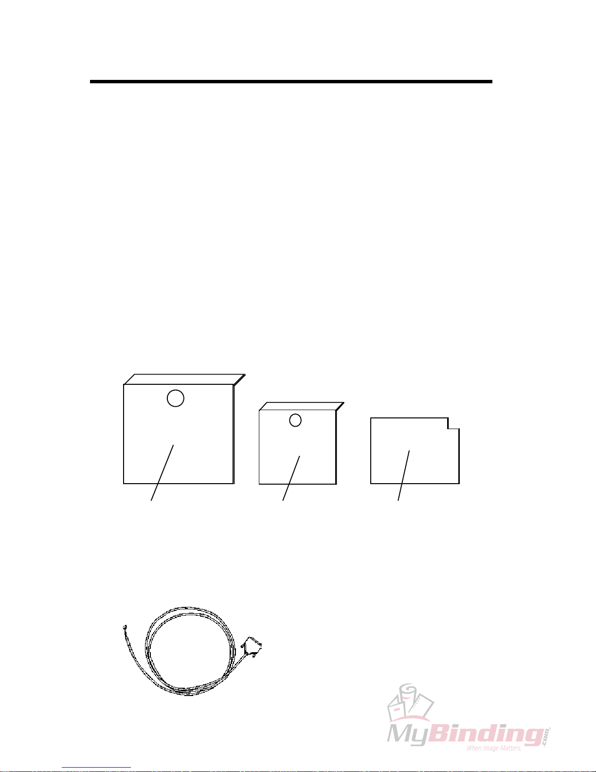
1.3 SPECIAL TOOLS
There is a tool set available, part number 600007, in order to facilitate adjustments
on BM 60/61.
Tool A Tool CTool B
To be able to download software to the PCB a download cable is required,
part number 770010.
5
2. COVER REMOVAL INSTRUCTION (CRI)
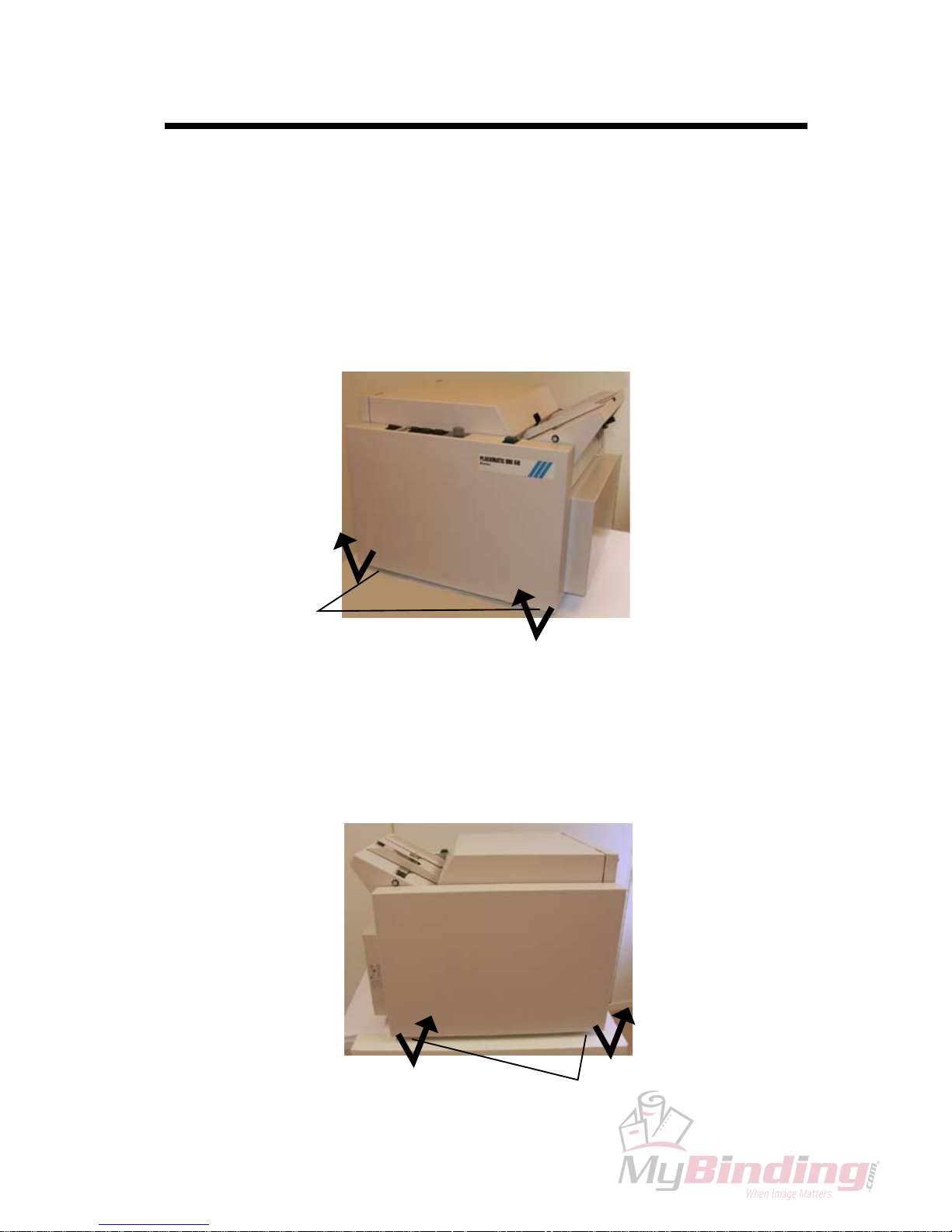
CRI 2.1 FRONT AND REAR COVER
Front Cover
Removal
Loosen the two screws (1).
Pull out the lower end and lift up to remove.
CAUTION: Lift carefully when removing front cover to prevent damaging the
wire harness to front panel.
1.
2.
Installation
Installation is an exact reversed procedure of removal.
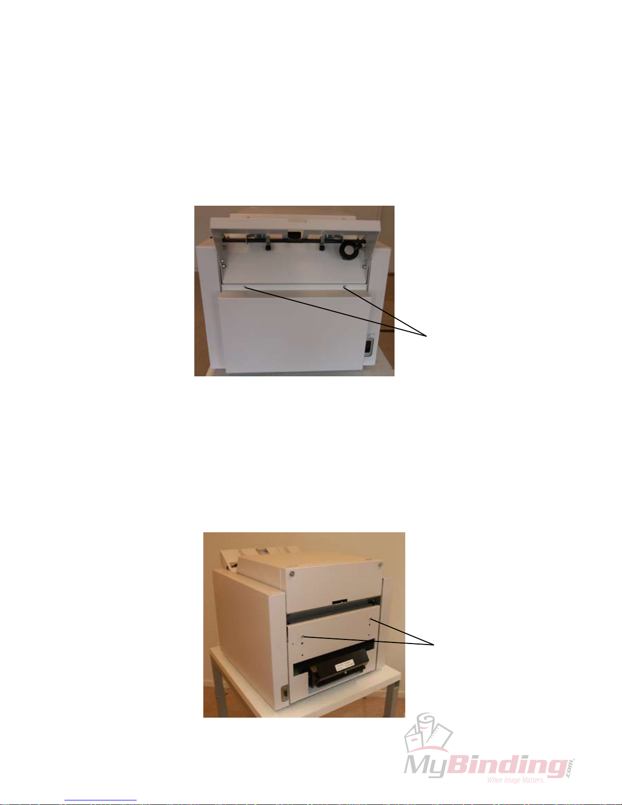
Rear Cover
Removal
Loosen the two screws (1).
Pull out the lower end and lift up to remove.
1.
1.
2.
Installation
Installation is an exact reversed procedure of removal. 1.
1
1
6
CRI 2.2 INFEED AND OUTFEED COVER
Infeed Cover
Removal
Remove the two screws (1).
Pull out the upper end of Infeed cover and open cover to horizontal position.
1.
2.
Installation
Installation is an exact reversed procedure of removal.
Outfeed Cover
Removal
Loosen the two screws (1).
Pull out the upper end of cover and open to horizontal position.
1.
1.
2.
1
1
7
3. REPAIRS/ADJUSTMENTS (REP)
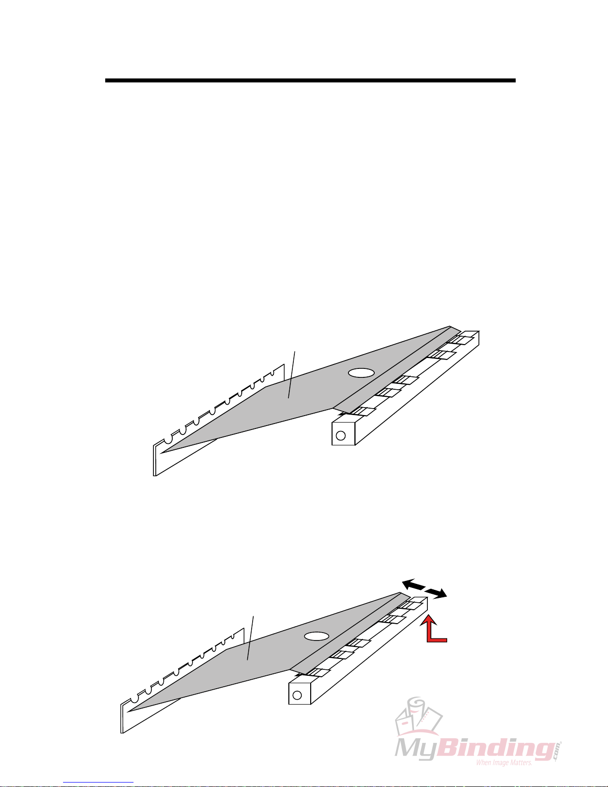
REP 3.1 PARALLELISM FOLD KNIFE - ANVIL BAR
Purpose
The purpose is to align the Anvil bar with the Fold knife to obtain a correct staple
position.
Switch off the main power switch and disconnect the power cord.
Remove Front, Rear and Infeed cover according to CRI 2.1 and 2.2.
Move the Fold knife to top position by turning the shaft on rear side of Fold
knife Motor manually.
Move the Side guides to outer position.
Insert tool
A and check that the Anvils are aligned with the edge of tool A.
1.
2.
3.
4.
5.
Adjustment
Loosen the screw holding the Anvil bar a fraction on the rear side of machine.
Tap carefully on the screw with a hammer to position the Anvil bar.
Tighten the screw.
CAUTION: Do not move the Anvil bar up or down, that could cause the stapling
pressure to be uneven.
1.
2.
3.
Tool A
Tool A
Loosen screw
on this side
8
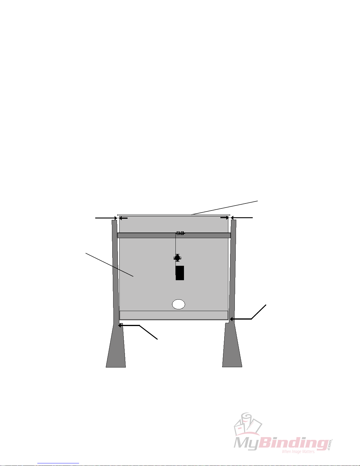
Purpose
The side guides needs to have the correct position in order to transport the set
straight to the fold stop.
Switch off the main power switch and disconnect the power cord.
Remove Infeed cover, according to CRI 2.2.
Empty Stapler magazines.
Move Fold knife to top position by turning the shaft on rear side of fold knife
manually.
Tighten the Side guides in the outer most position and insert tool A.
Move tool A until the Side guide’s inner point is ush to tool.
1.
2.
3.
4.
5.
6.
Adjustment
Loosen screws holding Side guides and adjust so that the guides are parallel to
tool.
1.
REP 3.2 ADJUSTMENT OF SIDE GUIDES BM 60
Tool A
VIEW FROM TOP SIDE
0.25-0.50 mm
Adjust on these screws
Side guide ush to tool
Fold knife
0.25-0.50 mm
9
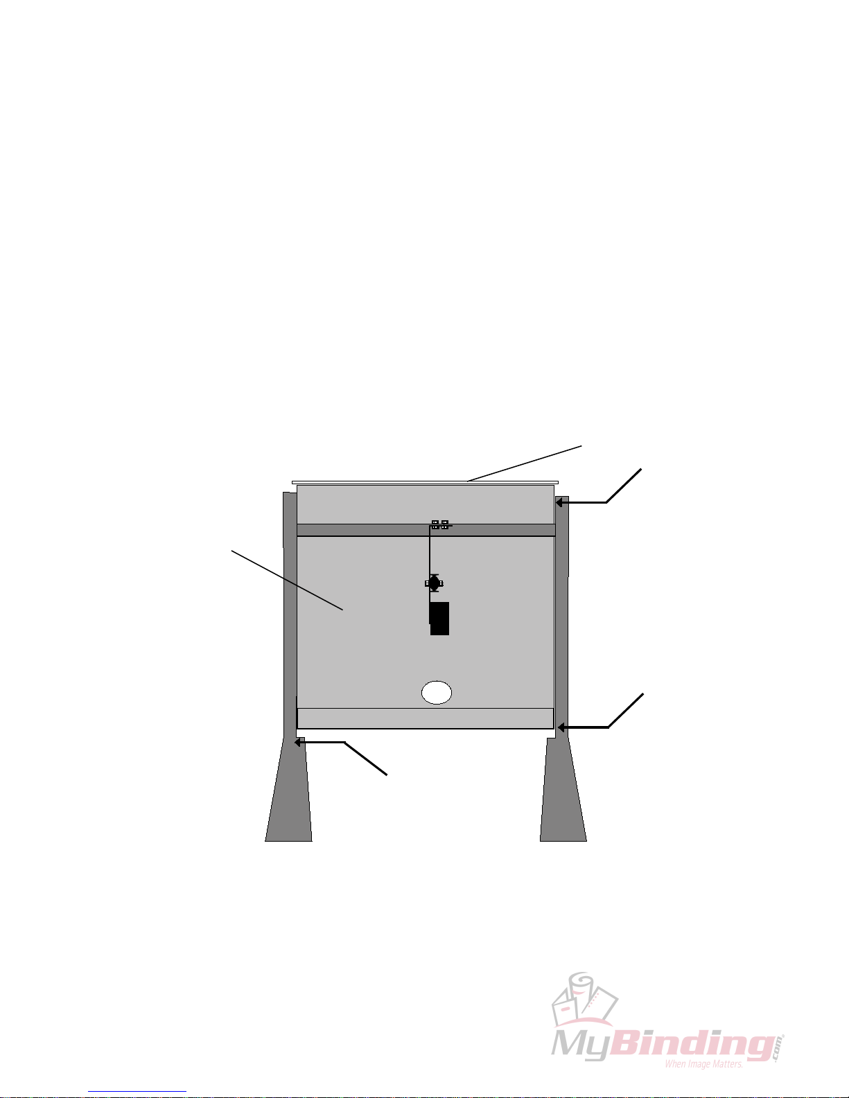
REP 3.3 ADJUSTMENT OF SIDE GUIDES BM 61
Purpose
The Side guides needs to be exactly parallel in order to transport the set straight to
the Fold stop.
Switch off the main power switch and disconnect the power cord.
Remove Infeed cover, according to CRI 2.2.
Empty the Stapler magazines.
Move the Fold knife to top position by turning the shaft on the rear side of Fold
knife motor manually.
Move the Side guides to the outer most position and insert tool A.
Check that the Side guides are ush to tool.
1.
2.
3.
4.
5.
6.
Adjustment
Loosen the screws holding the Side guides, adjust until the Side guides are
ush along the side of tool A.
1.
VIEW FROM TOP SIDE
Fold knife
Side guide ush to tool
Side guide ush to tool
Adjust on these screws
Tool A
10
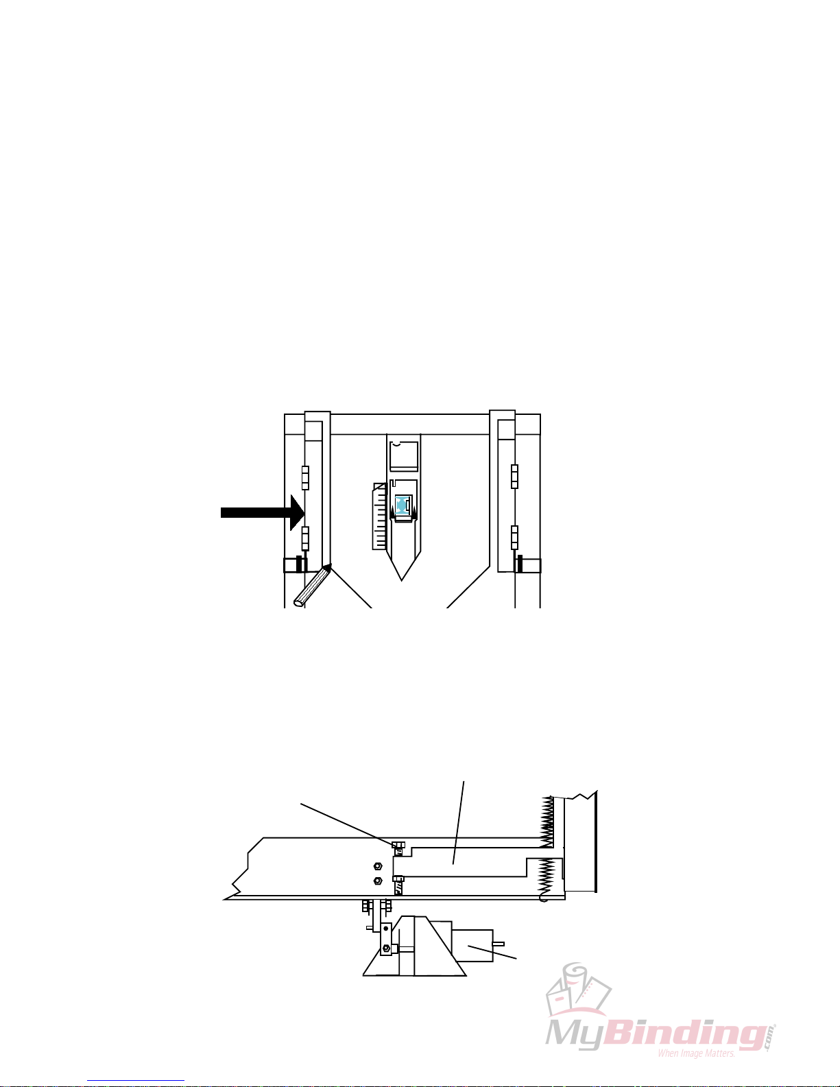
REP 3.4 ADJUSTMENT OF SIDE JOGGER MOVEMENT
BM 61
Purpose
On the BM 61 the side jogging is performed with the rear jogging rail. The jogging
stroke is essential to the jogging performance and the transport of sets to the fold
area.
Switch off the main power switch and disconnect the power cord.
Remove Infeed cover, according to CRI 2.2.
Push the jogging rail in manually and make a mark with a pen, release the jog-
ging rail and measure the distance from the mark to the jogging rail. The jogging movement should be 3.5 +/- 0.5 mm.
1.
2.
3.
Adjustment
Locate the Jogger arm assembly close to the Stapler motor.
Adjust on screw (1) to obtain 3.5 +/- 0.5 mm jogging movement.
1.
2.
Push here
VIEW FROM TOP
Jogger arm assy
Stapler motor
1
11
REP 3.5 PARALLELISM STAPLE STOP - ANVILS
Purpose
The purpose is to obtain the correct staple position.
Switch off the main power switch and disconnect the power cord.
Empty Stapler magazines.
Insert tool B according to the drawing and crank hand wheel to position upper
edge of tool at Anvils.
CAUTION: The clear Indicator switch could be damaged when inserting tool B.
1.
2.
3.
Adjustment
Loosen one of the screws at position (1) and two of the screws at position (2).
Adjust by skewing the staple stop carriage until tool B is aligned with the anvils.
Tighten the screws at position (1) and (2).
NOTE: If further adjustment is necessary to align tool B with the anvils, also loosen
screw (3).
1.
2.
3.
3
VIEW FROM TOP SIDE
1
Staple stop
2
Tool B
Anvil bar
 Loading...