

ISSUE 8
JULY
2009
DOCUMENT CREASING & AUTOMATIC
BOOKLET MAKING MACHINE
(Creasing Unit)
OPERATORS MANUAL (Part 1)
FROM SERIAL No. 780156 ONWARDS.
Documaster MK3
Website: www.morgana.co.uk
70-111
Morgana Systems Limited United Kingdom
Telephone: ( 01908 ) 608888 Facsimile: ( 01908 ) 692399

Page 2
INDEX
CREASING / BOOKLET MAKING
SAFETY Do’s & Don’ts 6
THE CREASING UNIT
9
THE CONTROL PANEL
10
11
SETTING THE MACHINE UP AS A CREASER
12
12
13
13
13
13
13
13
15
17
17
18
18
19
20
20
20
20
SETTING THE MACHINE UP AS A BOOKLET MAKER
22
22
23
24
24
25
25
25
26
26
28
28
29
30
31
Labelled Photograph
Detailed diagram and description
Features on the control panel
Adjusting the Paper Gate
Setting the Suction Slot
Setting the Vacuum Bleed
Setting the Adjustable Side Lay
Setting the Back Stop
Setting the Air Seperation Pressure
Setting the Roller Tilt Mechanism
Setting the position of the Drive Wheels and Hubs
Setting the Stacker Assembly
Programming the machine for Creaser Operation
Setting the Feed
Setting the Batch Quantity
Setting the Crease Positions
Storing the Crease Positions
Running the machine
Reading Stored Programs
Paper Jamming
Setting the Machine to Run in Manual Mode
Adjusting the Paper Guides
Adjusting the Sliding Back Stop
Programming the machine for Booklet Maker Operation
Setting the Feed
Setting the Page Length
Setting the Book Centre
Setting the Sheet Width
Setting the number of Sheets in the Book
Setting the Crease Style
Setting the Cover Crease
Setting the Stitch Position
Setting the Machine to Edge Stitch
Setting the Set Knock
Setting the Trimmer
Setting the Batch Quantity
Setting the Air Distribution 13
INTRODUCTION
PAGE 4The Morgana Documaster Mk3

Page 3
SYSTEM
INDEX
31
31
32
32
33
34
37
PERFORATING
39
40
THE BLADE ASSEMBLY
42
43
REPLACING CREASING BLADE SETS
44
45
TROUBLE SHOOTING 46
ERROR MESSAGES 49
DISPATCH KIT 50
ACCESSORIES AND OPTIONS 51
RECOMMENDED SPARES 52
MACHINE CALIBRATION HISTORY 54
PRODUCT RECYCLING & DISPOSAL 55
Storing the Program
Running the Machine
Reading Stored Programs
Clearing Booklet Sheets from the Booklet Maker Infeed Tray
Using the Booklet Maker in Manual Mode (Hand Feed)
Using the Optional Camera Recognition System (Fixed Data)
Using the Optional Camera Recognition System (Variable Data)
Equipment, spares
Setting the machine
Setting the blade pressure
Setting the blade alignment
Installing new blade sets
Spares
DocuMaster MK3

Page 4
CREASING / BOOKLET MAKING
INTRODUCTION
The crease is programmed from the leading edge of the sheet using the
controls on the front panel.
The blade and anvil are mechanically controlled over their entire length
and can be adjusted to accommodate various weights of media
.
Maximum sheet size:- 630mm x 330mm (24.8” x 13”)
Minimum sheet size:- 210mm x 140mm (8.27” x 5.5”)
Maximum sheet weight:- 400 gsm
Minimum sheet weight:- 80 gsm (160 gsm when creasing and folding).
Maximum number of creases:- Nine
Minimum distance between creases:- 4.0mm
Minimum incremental adjustment:- 0.1mm
Minimum crease distance from leading edge:- 30.0mm (1.2”)
Minimum crease distance from trailing edge:- 30.0mm (1.2”)
Production up to 5000 sheets / hour, (one crease on A4 sheet).
CREASER UNIT SPECIFICATION
The Morgana DocuMaster MK3 is a fully automatic, suction feeding, creasing
/ booklet making system; designed for use with both conventional litho and
digital printers.
the operating environment should be controlled to a temperature
between 10
The system comprises a creasing unit linked to a fully automatic booklet
making machine, the creasing unit and booklet maker can be used
separately to give optimum flexibility.
The feed system incorporates an ultrasonic detector system to ensure
complete booklet integrity.
The feed on the Documaster MK3 can also be manually operated for use with
heavy stock, very small or very large sheets, embossed or even irregular
sheets.
IMPORTANT
°°C and 30 C and at 35 - 85% relative humidity.
DocuMaster MK3

Page 5
SYSTEM
BOOKLET MAKER UNIT SPECIFICATION
Maximum sheet size:- 460mm x 320mm (18.1” x 12.6”)
Minimum sheet size:- 210mm x 140mm (8.27” x 5.5”)
Maximum staple pitch:- 138mm (5.4”)
Minimum staple pitch:- 115mm (4.5”)
Maximum number of sheets in book:- 20 sheets (80 gsm)
Maximum cover weight :- up to 350 gsm
Minimum inside sheet weight:- 80 gsm
Maximum trim:- 25mm (1”)
For optimum performance the difference between the cover and the
inside sheet should be no more than 110 gsm.
Production up to 1560 books / hour, (dependant on number of sheets in book).
DocuMaster MK3

Page 6
CREASING / BOOKLET MAKING
Safety Do’s & Don’ts
Safety Do’s & Don’ts
Do - read this operator manual fully before operating the machine.
Do - operate with the designated AC current only. Use an exclusive outlet, as
overloading may cause fire or an electric shock.
Do - install the power cord out of the way to avoid a tripping hazard.
Do - make sure that the mains inlet connector is always easily accessible.
Do not - install the machine in an unstable place such that it tilts or shakes.
Do not - unplug the plug or unplug the power cord from the outlet with a wet hand,
this can cause an electric shock.
Do not - unscrew and remove any covers from the machine, as it can cause an
electric shock or injury.
Do not - place receptacles containing liquids on any surface.
Do not - adjust any part of the machine whilst rollers are running
Do not - operate the machine with loose or trailing clothing or loose hair.
Do not - under any circumstances adjust the paper gate when the machine is
switched on.
REGLES DE SECURITE : « A FAIRE » ET « A NE PAS FAIRE »
Lire ce mode d'emploi avant d'utiliser la machine.
Respecter l'alimentation électrique indiquée. Brancher sur une prise séparée
car une surcharge peut entraîner un incendie ou un choc électrique.
Installer le cordon d'alimentation de manière à ne pas pouvoir
trébucher par dessus.
Ménager un accès libre à la prise de courant.
Ne pas installer la machine sur une surface non plane, afin d'éviter
qu'elle ne penche ou ne vibre.
Ne pas installer la machine sur une surface non plane, afin d'éviter
qu'elle ne penche ou ne vibre.
Ne démonter et enlever aucun carter de la machine, par crainte de décharge
électrique ou de blessure.
Ne pas placer de récipient contenant un liquide sur la machine.
N'effectuer aucun réglage pendant que les rouleaux fonctionnent.
Ne pas porter de vêtements flottants et rassembler les cheveux longs
lors de l'utilisation de la machine.
En aucune circonstance, régler le séparateur de papier lorsque la
machine est branchée.
Safety Do’s & Don’ts
Page 7
SYSTEM
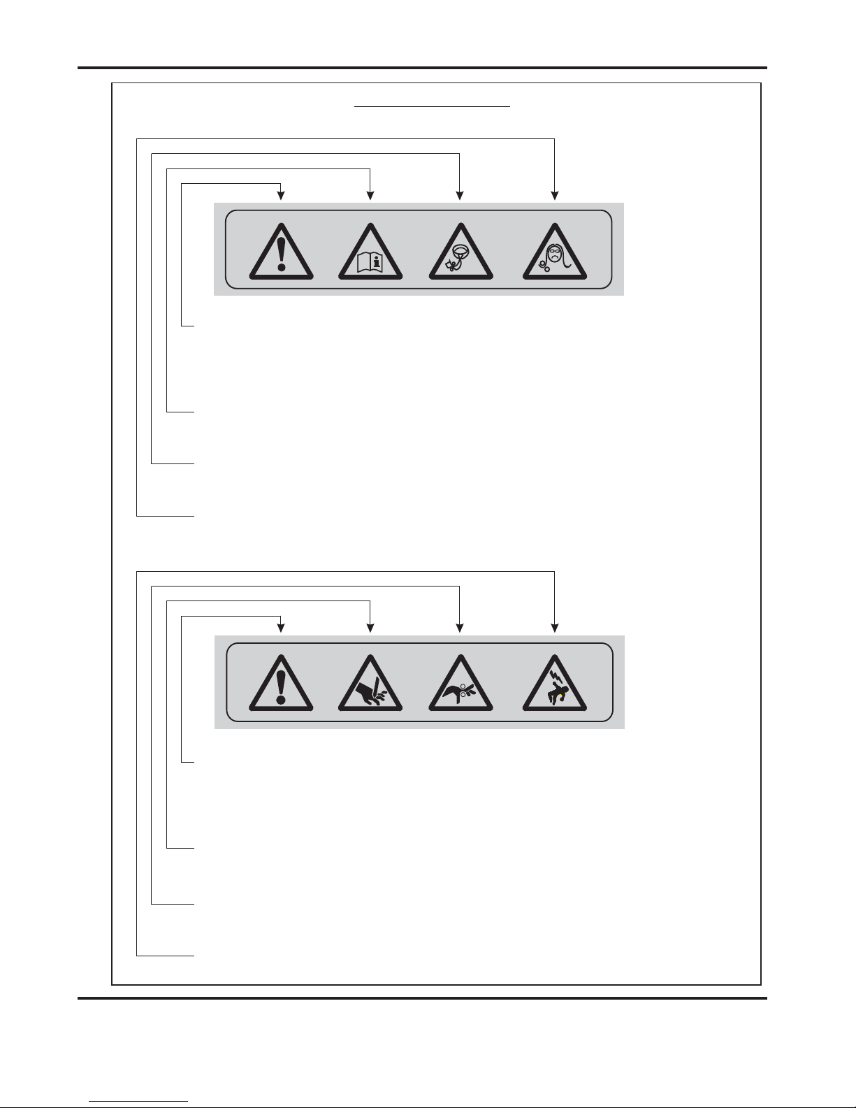
Warning Labels
Do - be aware of any finger traps and rotating parts when operating
the machine.
Do - read this operator manual fully before operating the machine.
Do not - operate the machine with loose or trailing clothing.
Do not - operate the machine with loose hair.
Do - be aware of any finger traps and rotating parts when operating
the machine.
Do - be aware of sharp points and blades.
Do - be aware of rotating rollers.
Do - be aware of low current anti-static shock.
Attention au risque de se coincer les doigts, et aux pièces en
mouvement lors du fonctionnement de la machine.
Ne pas porter de vêtements flottants lors de l'utilisation de la machine
Rassembler les cheveux longs lors de l'utilisation de la machine.
Attention au risque de se coincer les doigts, et aux pièces en
mouvement lors du fonctionnement de la machine.
Attention aux éléments tranchants et aux couteaux.
Attention aux rouleaux en fonctionnement
Attention aux faibles chocs d'électricité statique
Lire ce mode d’emploi avant d’utiliser la machine.
DocuMaster MK3

Page 8
CREASING / BOOKLET MAKING
BLANK
PAGE
Page 9
SYSTEM
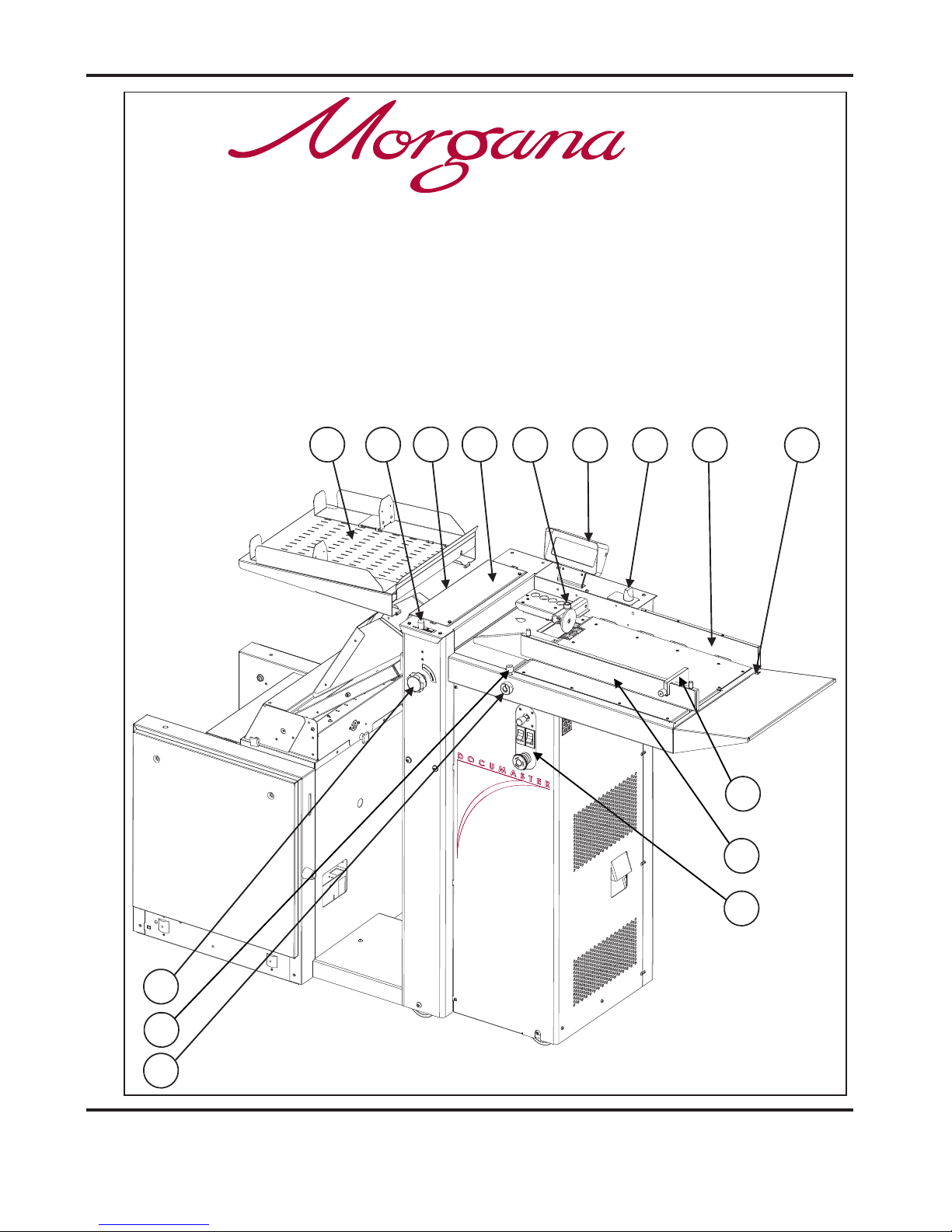
THE CREASING UNIT
5
2
1
15
12
11
6
9
14
8
7
4
3
10
13
Key to photograph below
1 Roller tilt handle 6 Air separation knob 11 Paper Gate
2 Stacker assembly 7 Adjustable side lay 12 Exit Guard
3 Suction slot knob 8 Back stop 13 Vacuum Bleed Knob
4 The control panel 9 Fixed side lay 14 Display
5 Air distribution knob 10 Roller tilt knob 15 Anti-Static Unit
DocuMaster MK3
DocuMaster MK3

Page10
CREASING/BOOKLETMAKING
THECONTROLPANEL
SystemSwitch
CompressorSwitch
EmergencyStopSwitch
SelectionSwitch
THECONTROLS
TheDisplayUnitandtheSwitchesontheControlPanelallowthe
operatortoread,edit,createandinitiatenumerouscreasingprogramswithin
thememory.
TheControlPanelhousestheSelectionSwitch,Compressorswitch,
Systemswitch,andanindustrystandardEmergencyStopswitchwhich
willstopallpowergoingtothemachinewhenactivated.

Page 11
THE CONTROLS
SYSTEM
Features on the Control Panel
Selection Switch
System switch
Compressor switch
Allows the operator to scroll through stored addresses and programs, increase or
decrease the batch quantity and set a crease position.
When activated the system switch will operate the motors in order to begin the
creasing sequence.
Allows the operator to switch off the compressor unit in order to utilise the machine
to manually feed sheets.
DocuMaster MK3

Page 12
Adjustable
Side Lay
J
K
6.5mm (1/4")
TWO THICKNESSES
OF PAPER
Suction
Slot Knob
IMPORTANT:-
To avoid possible damage to the suction drum,
when adjusting the paper gate height, ensure that
drum and not over a slot in the drum.
the disc is located over a solid section of the suction
Do not adjust the paper gate while the machine is
running.
CREASING / BOOKLET MAKING
Vacuum
Bleed Knob
Setting the Machine up as a Creaser
Adjusting the Paper Gate
The standard setting for horizontal adjustment of the paper gate is 6.5mm (1/4") away
from the mounting block. Turn disc J to make this adjustment. This setting is only intended
as a guide, for instance, sheets with an upward curl will require this setting to be increased. Set the height of the Paper Gate to approximately two thicknesses of paper, by
turning knob K. An excessive gap is a most likely cause of double sheet feeding.
Setting the Suction Slot
The suction slot is located inside the vacuum roller and can be adjusted by releasing and
moving the suction knob horizontally in either direction to the required position.
For light stocks set the knob to the left and for heavier stocks set the knob to the right.
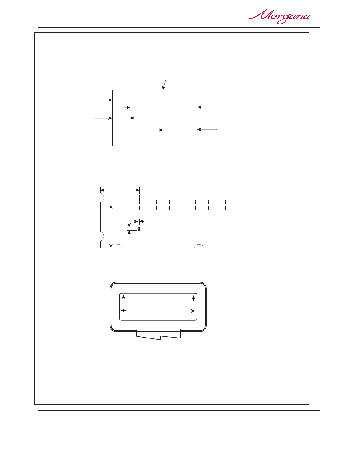
FIG 8.1

Page 13
SYSTEM
Setting the Machine up as a Creaser
Setting the Vacuum Bleed
Setting the Adjustable Side Lay
Setting the Back Stop
Setting the Air Distribution
Setting the Air Separation Pressure
Place the paper stack on to the loading table and slide up to the fixed side lay and paper
Gate. Release the clamps located at each end of the side lay and slide up towards the
paper stack as demonstrated in FIG 8.1. Allow a gap of approximately 0.5mm (1/64 inch)
between the paper and the side lay.
When using heavy stocks or large paper stacks, the feeding of the sheets may be improved
by fitting the Clamp Plates to the Adjustable Side Lay, as shown in FIG 8.2 below; but
please be aware that they may cause double feeding when using light stocks.
Position the backstop and slide up towards the paper stack allowing a gap (as specified
in the above step).
Depending on the length of the sheet to be creased, the air distribution knob can be
rotated to various positions in order to supply air to different ports. Position 1 is
recommended for most sheet sizes. However, a better result may be obtained by using
the settings below or by experimentation.
For A5 sheets or 8 inches long, front port and port 1 open.
For A4 sheets or 11 inches long, front port and port 2 open.
For A3 sheets or 17 inches long, front port and port 3 open.
For longer sheets in order to supply air to the centre of the stack, port
1 and port 2 open.
To control the amount of air supplied to the ports, the air separation knob can be adjusted
by first rotating the knob to unlock its position, then push the knob down to the required
position and rotate the knob to re-lock its position.
NOTE.
Position 1 -
230-
Situated on the front of the feed table, the Vacuum Bleed Knob is used to allow more
control of the suction on the vacuum drum.
When light weight paper of 90gsm and lower is being fed through the machine turn the knob
clockwise to reduce the possibility of marking, or damage to the leading edge of the paper.
FIG 8.2
Clamp Plates
DocuMaster MK3

Page 14
FIG 10.1
CREASING / BOOKLET MAKING
Setting the Machine up as a Creaser
Setting the Roller Tilt Mechanism
Setting the positions of drive wheels and hubs
The roller tilt mechanism has been designed to compensate for when the creasing
position on the sheet is not square. This could be due to an inaccuracy in the media or if
the roller tilt mechanism has been incorrectly set. The mechanism will be set to zero
(square) when the machine is supplied.
To set the mechanism, unlock the roller tilt knob located below the roller tilting handle by
turning anti- clockwise. Move the roller tilt handle left or right in order to compensate for
any inaccuracy. When the position is set, ensure to lock the roller tilt knob before
operating the machine. Repeat the above procedure until the creasing position is square.
It is important that the drive wheels and drive hubs on the roller shafts are arranged evenly
across the width of the media being creased. This is done to ensure that the media is
accurately driven and supported through the rollers.
The drive wheels and hubs are fixed to the rollers by means of a grub screw. To locate
this grub screw the rollers can be rotated by operating the motor manually.
To operate the motors manually, switch the machine ‘on’ at the Emergency Stop switch.
Following the arrows on the display unit, move the selection switch to the left to select
, the display will now show the Tools sub-menu. Press the system switch down and
then move the selection switch to the left or to the right, to rotate the rollers in short pulses.
Lift the exit guard to see if the grub screws in the drive wheels and hubs can be seen. If the
grub screws cannot be seen, lower the exit guard and rotate the rollers by moving the
selection switch to the left or to the right. Loosen the drive wheels and hubs with a 2mm
allen key. Arrange the drive wheels and hubs as shown in FIG 10.1. In order to avoid
marking on some types of media ensure a gap between the drive wheels and hubs.
This procedure should be repeated when installing perforating blades and anvils onto the
drive wheels and hubs.
DO NOT ROTATE THE DRIVE ROLLERS BY HAND
.
Tools
Page 15
SYSTEM
Setting the Machine up as a Creaser
LEFT HAND
SIDE GUIDE
FIG 13.1
RIGHT HAND
SIDE GUIDE
LEFT HAND
BACK STOP
RIGHT HAND
BACK STOP
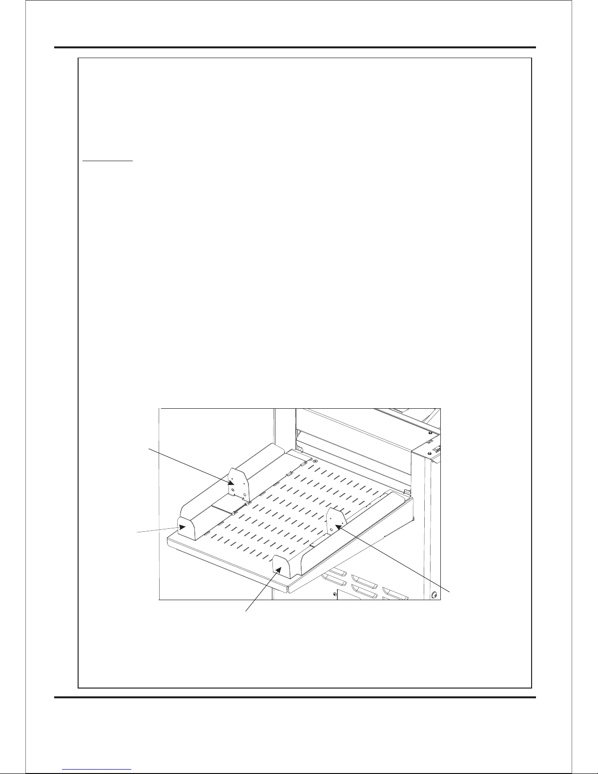
Setting the Stacker assembly
The stacker unit on the machine is used to catch the sheets once they have been
creased or perforated.
NOTE:- This stacker unit is not fitted when the machine is being used as a Booklet maker.
1. Assemble the stacker unit to the machine as shown in fig 13.1 below.
There are two side guides on the stacker unit; a left handed guide and a right handed
guide. The guides will control the way in which the paper is collated by setting their
positions on the stacker bed.
2. Place a single sheet (from the stack to be creased / perforated) on to the stacker bed
against the ‘left hand’ guide.
3. Position the ‘right hand’ side guide on to the stacker bed leaving a minimum
clearance of approximately 1mm each side of the sheet.
Important
Ensure that the stacker unit has been assembled to the machine properly. However,
if it has not, the connection on the magnetic switch will be broken and the machine
will not operate (see Trouble shooting pages for details).
DocuMaster MK3
Page 16
CREASING / BOOKLET MAKING
Setting the Machine up as a Creaser
4. Whilst the sheet is between the two guides on the stacker bed, set the distance .
between the top of the sheet and the backstop flanges to approximately 5mm.
5. For shorter sheets, the back stop can be used (as shown in FIG 13.1 to adjust the
position of the paper stack.
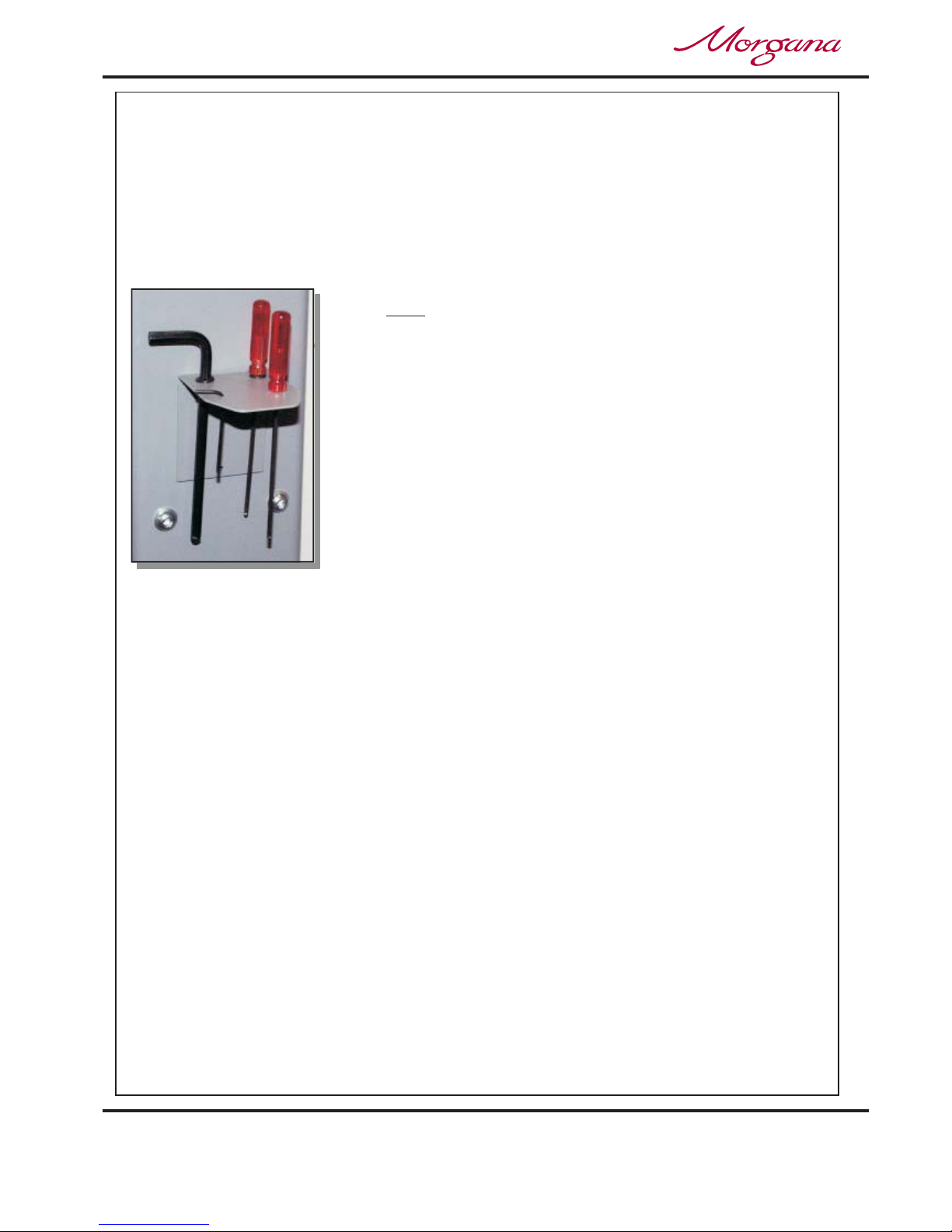
TIPS
! The magnetic back stop supplied with the machine
can also be used as a tool holder as demonstrated
In the photograph (left).
Page 17
SYSTEM
Setting the Machine up as a Creaser
1 Creases
Program 1
To ta l 2 0
Reset
Setup
Tools
Feed
Batch Off
Autocreaser
Operate This Machine
No
Yes
Are You Trained To
2. If the text on the display contains the word the machine is in the
Booklet Maker mode of operation.
To change to the Creaser mode of operation proceed as follows:-
(i) Move the selection switch up to select .
(ii) Move the selection switch down to .
(iii) Move the selection switch to the right to select .
3. The length of suction on the sheet of paper being fed can be adjusted by setting the
feed type as follows:-
(i) Move the selection switch to the right to select .
(ii) Move the selection switch down to select the required feed type ( ,
, , or )
(iii) Move the selection switch to the right to select .
‘Book’
Set Feed
Reset
Mode to Autocreaser
Mode to Autocreaser
Setup
Long Pulse
Medium Pulse Short Pulse Stream Feed
Select
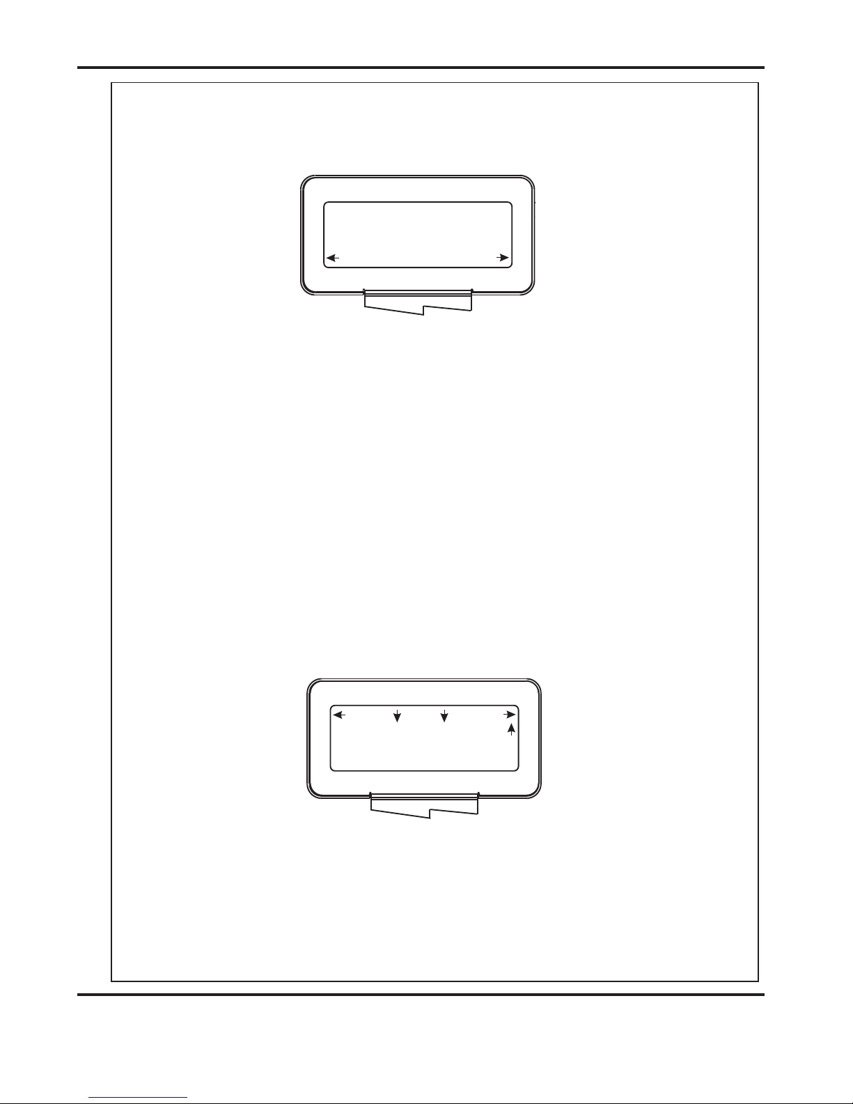
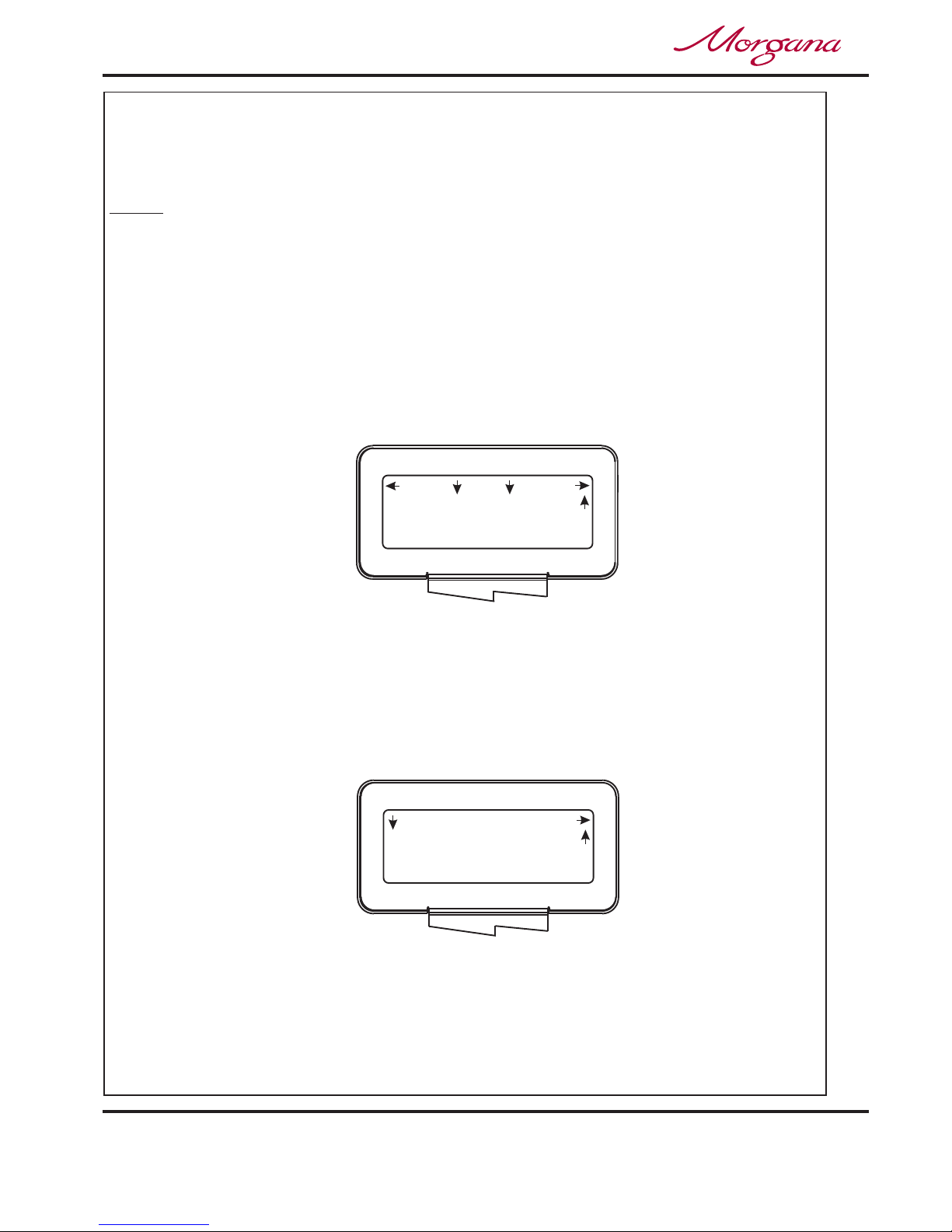
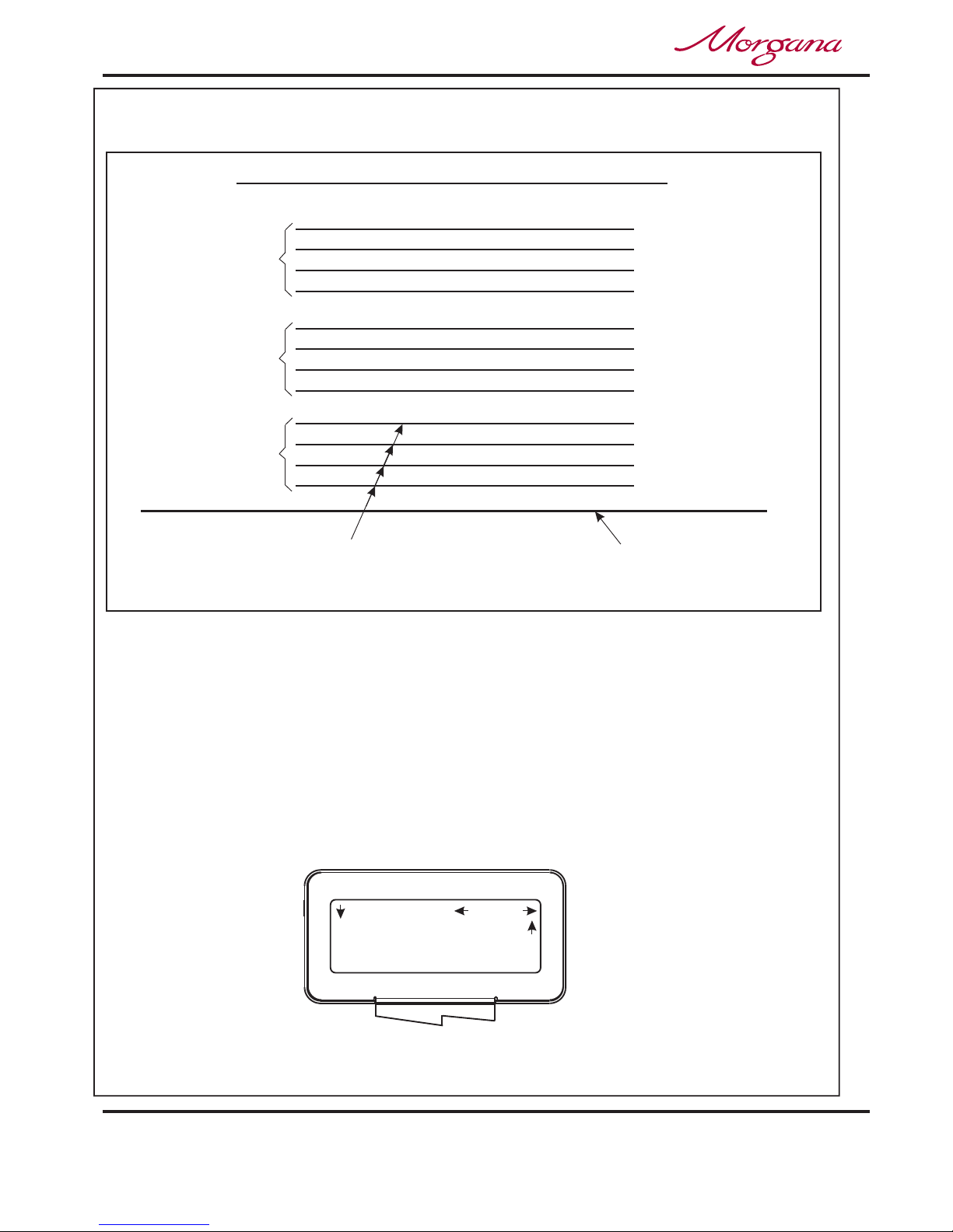
A typical Autocreaser display menu is shown below.
IMPORTANT.
Programming the machine for Creaser operation
1. Switch the power ‘on’ by turning the Emergency stop button clockwise to release the
safety latch. The display is now switched on and will be as shown below.
If you have not been trained to operate this machine, we strongly advise that you move the
selection switch to the right to select . We recommend that you either seek training or
ask a trained operator to run the machine for you.
Move the selection switch to the left to select only if you have been trained to operate
this machine. If you have not been trained to operate this machine and you select ,
Morgana Systems Ltd accept no responsibility for personal injury, damage to the
machine or damage to materials being processed by the machine.
No
Yes
Yes
MORGANA
DocuMaster MK3
Page 18
CREASING / BOOKLET MAKING
Setting the Machine up as a Creaser
0 Creases
Program 3
To ta l 2 0
Reset
Setup
Tools
Feed
Batch Off
Autocreaser
2nd Crease 0.0
1st Crease 297.0
Home
More
Set Creases
Use for all standard size sheets, general purpose.
Use for short non-standard sheets.
Use for very short sheets.
Use for high throughput, see note below.
Do not use stream feed for creases less than 32mm from the leading edge of the paper.
4. (ii) Move the selection switch to the right to select .
(iii) Move the selection switch down to select .
(iv) Rotate the selection switch clockwise or anti-clockwise to adjust the batch quantity
in increments of 5.
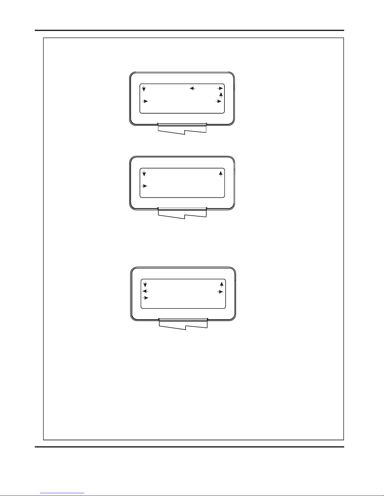
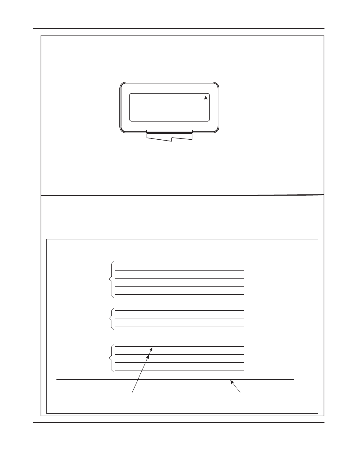
5. Move the selection switch up, one click at a time, until the start up menu is displayed,
(A typical start up display menu is shown below).
(i) Move the selection switch to the right to select .
(ii) Move the selection switch to the right, one click at a time, selecting ;
until the display shows as shown below.
(iii) Following the arrows on the display unit; move the selection switch down to set the
creases. The 1st Crease is now selected.
Long Pulse
Medium Pulse
Short Pulse
Stream Feed
More
Batch Quantity
Setup
More
Set Creases
NOTE.
Setting the batch quantity
Setting the crease positions
NOTE:-
The arrows on the display denote the direction in which the selection
switch must be moved in order to access the various sub-menus.

Page 19
SYSTEM
Setting the Machine up as a Creaser
Back
Tens Decimals
2nd Crease 0.0
( 1st Crease 297.0 )
Set Creases
Back
Tens Decimals
3rd Crease 0.0
( 2nd Crease 0.0 )
Set Creases
Batch 20
To ta l 8 0
No Program
Reset
Setup
Tools
Feed
2 Creases
Autocreaser
(iv) Move the selection switch to the left to select Tens, or to the right to select Decimals.
(v) The Tens or Decimals (whichever has been selected) can then be adjusted by
rotating the Selection Switch, (clockwise to increase or anti-clockwise to decrease).
(vi) Adjust all other digits for the 1st Crease position as described in steps (iv) and (v),
(i.e. move the selection switch to the left to select the Tens or to the right to select
Decimals and then rotate the Selection Switch to adjust its value.
(vii) To set the 2nd Crease position move the selection switch down; the 2nd crease is
selected and can be set as described in steps (iv) to (vi) above.
Crease positions can be set in increments of 0.1mm. Further creases can be set in
this way, up to a maximum of nine creases.
(viii) When the required creases have been set, move the selection switch up, one click
at a time, until the display contains the word , see below.
6. Once the crease positions are correctly entered, they can be stored as follows.
(i) Move the selection switch to the right to select .
(ii) Move the selection switch to the right, one click at a time, (selecting ) until the
display contains the word .
(iii) Move the selection switch down to select
(iv) Rotate the Selection Switch to select the Program number (1 to 9).
(v) Move the selection switch to the right to select .
(vi) Move the selection switch to the left to select or to the right to select
Feed
Setup
More
Programs
Save Settings.
Select
Yes No.
Storing the crease positions
DocuMaster MK3

Page 20
CREASING / BOOKLET MAKING
Setting the Machine up as a Creaser
Running the machine
In order to manually feed sheets see instructions below.
Reading stored programs
Paper jamming
Setting the machine to operate in manual mode
7. To run the job with the selected settings.
(i) Press the Compressor Switch down.
(ii) Press the System Switch down.
(iii) Move the selection switch down to begin feeding the sheets.
To stop feeding the media at anytime during the program, flick the selection switch up.
The machine will complete its creasing operation if a sheet has already been fed
through the paper gate.
Any of the nine stored programs can be accessed and read as follows:-
(i) From the start up menu, move the selection switch to the right to select .
(ii) Move the selection switch to the right, one click at a time, until the display contains
the word .
(iii) Move the selection switch down to select, .
(iv) Move the selection switch to the right to select, .
(v) Rotate the selection switch clockwise or anti-clockwise to select, to
and view the program settings.
In the event of a paper jam occurring whilst the machine is operating the display will
read In order to remove the paper causing the jam, move the selection switch
to the left or to the right to drive the paper forwards or backwards in short pulses.
In order to feed heavy stock, very small or very large sheets, embossed or even
irregular shaped sheets, it may be required to operate the machine manually.
The machine can be programmed and set up in exactly the same way as explained
when operating the machine automatically. However, when setting up the machine the
paper gate must be raised to its highest position for the sheets to be fed freely.
Operating the machine manually will also require the suction length to be continuous in
order to accommodate various types of stock. Therefore, the feed should be set to
see page 17.
The machine can now be started by activating the System switch to ‘on’.
Move the selection switch down to select and
begin to slide the sheets individually through the paper gate until they are driven by the
drive belts. To stop feeding the sheets, move the selection switch up and then the System
Switch up.
Setup
Programs
Retrieve Program
Select
Program 1
Program 9
Paper Jam.
Long Pulse
Do not
activate the Compressor switch. Feed

Page 21
SYSTEM
BLANK
PAGE
DocuMaster MK3

Page 22
CREASING / BOOKLET MAKING
Rear Paper Guide
Sliding Back
Infeed Tray
Front Paper Guide
Setting the Machine up as a Booklet Maker
Paper Guide Adjustment Lever
Stop
(On Underside Of Infeed Tray)
Adjusting the Paper Guides
Adjusting the Sliding Back Stop
Inse he infeed tray of the Booklet Maker. Adjust the width
of the paper guides, by sliding the lever (on the underside of the infeed tray)
forwards or backwards until the sample sheet slides freely in the guides.
With the sample sheet in its downward resting position, adjust the sliding back
stop until it is approximately 5mm to 10mm clear of the back edge of the sample
sheet.
rt a sample sheet into t

Page 23
SYSTEM
Variable Data
Prog 3
Books 9
Reset
Setup
Tools
Feed
Image Rec on
Operate This Machine
No
Yes
Are You Trained To
Programming the machine for Booklet Maker operation
1. Switch the power ‘on’ by turning the Emergency stop button clockwise to release the
safety latch. Allow the booklet maker to run through its program, it will confirm a ready
signal with two blips and a constant flashing of its light. If the light does not constantly flash
and the optional Square Back System is fitted, make sure that the Square Back System
mains switch is switched on. The display is now switched on and will be as shown below.
IMPORTANT.
If you have not been trained to operate this machine, we strongly advise that you move the
selection switch to the right to select . We recommend that you either seek training or
ask a trained operator to run the machine for you.
Move the selection switch to the left to select only if you have been trained to operate
this machine. If you have not been trained to operate this machine and you select ,
Morgana Systems Ltd accept no responsibility for personal injury, damage to the
machine or damage to materials being processed by the machine.
2. If the text on the display contains the word the machine is in the
Creaser mode of operation.
To change the mode of operation to Booklet Maker mode proceed as follows:-
No
Yes
Yes
‘Autocreaser’
MORGANA
DocuMaster MK3
(i) Move the selection switch up to select .
(ii) Move the selection switch down to .
(iii) Move the selection switch to the right to select .
3. Adjust the Paper Gate, Adjustable Sidelay etc, as described on pages 12 to
14 (Setting the Machine up as a Creaser).
Reset
Mode to Documaster
Mode to Documaster
A typical Booklet Maker display menu is shown below.

Page 24
CREASING / BOOKLET MAKING
Setting the Machine up as a Booklet Maker
Back
Tens Decimals
Book Centre 130.5
Sheet Length 295.5
Set Booklet
Set Feed
Set Booklet (Standard Sheet Sizes).
Set Booklet (Custom Sheet Sizes).
4. The length of suction on the sheet of paper being fed can be adjusted by
setting the feed type as follows:-
(i) Move the selection switch to the right to select .
(ii) Move the selection switch down to select the required feed type ( ,
, , or )
(iii) Move the selection switch to the right to select .
Use for all standard size sheets, general purpose.
Use for short non-standard sheets.
Use for very short sheets.
Use for high throughput, see note below.
Do not use stream feed for creases less than 32mm from the leading edge of
the paper.
Once set, these sizes can be adjusted as required; by following steps 5B to 11.
Setup
Long Pulse
Medium Pulse Short Pulse Stream Feed
Select
Long Pulse
Medium Pulse
Short Pulse
Stream Feed
NOTE.
NOTE.
(ii) Move the Selection Switch down to select the required sheet size, and then
move the Selection Switch to the right to select.
(as described on pages 24 to 32)
5A. A quick setup for a standard size sheet can be set as follows:-
For example A4/A5 - settings will be sheet size 297 x 210, trim size is 145
and number of sheets in book will be 1.
(i) From the Booklet Maker start up menu, move the Selection Switch to the
left to select , the display will now read .
5B. Custom sheet sizes are setup as follows:-
(i) Move the selection switch to the right to select .
(ii) Move the selection switch down to select .
Tools Quick Sizes
More
Set Booklet

Page 25
SYSTEM
Back
Tens Decimals
Sheet Width 180.0
Length 50.0
Set Booklet
Back
Tens Decimals
Sheet Width 180.0
Book Centre 130.5
Set Booklet
(iii) The can now be set as follows:-
Move the Selection Switch to the left to select or to the right to
select . The or (whichever has been selected)
can then be adjusted by rotating the Selection Switch, (clockwise to
increase or anti-clockwise to decrease).
(v) The can now be set as follows:-
Move the Selection Switch to the left to select or to the right to
select . The or (whichever has been selected)
can then be adjusted by rotating the Selection Switch, (clockwise to
increase or anti-clockwise to decrease).
(vii) The can now be set as follows:-
Move the Selection Switch to the left to select or to the right to
select . The or (whichever has been selected)
can then be adjusted by rotating the Selection Switch, (clockwise to
increase or anti-clockwise to decrease).
Sheet Length
Tens
Decimals Tens Decimals
Book Centre
Tens
Decimals Tens Decimals
Sheet Width
Tens
Decimals Tens Decimals
NOTE.
(iv) Move the selection switch down.
(vi) Move the selection switch down.
It is important to set the correctly. This will ensure that the Creaser
and Booklet Maker units are aligned for Booklet Making operation. The Creasing
unit automatically aligns with the Booklet Maker when the sheets are fed.
(viii) Move the selection switch down.
Sheet Width
DocuMaster MK3

Page 26
CREASING / BOOKLET MAKING
Setting the Machine up as a Booklet Maker
3 Sheet Book
Prog 3
Books 9
Reset
Setup
Tools
Feed
Back
(Variable Data)
Set Booklet
Sheets in Book ?
(ix) The number of can now be set by
rotating the Selection Switch, (clockwise to increase or anti-clockwise to
decrease). Range:- 1 to 20 sheets (including cover).
Sheets in Book (Including Cover)
NOTE:If the selection switch is turned fully anti-clockwise the display will show
‘Sheets in Book ?’ ‘(Variable Data)’ as shown on next page. This setting is
used when the optional ‘Camera Recognition System’ is fitted and the
number of sheets in the Booklet are variable.
Setting the Crease Style.
(ii) Move the selection switch to the right, one click at a time, (selecting )
until the display contains the words .
More
Crease Style
6. From the Booklet Maker start up menu, the can be set as
follows:-.
(i) Move the selection switch to the right to select .
Crease Style
Setup
Back
(Including Cover)
Set Booklet
Sheets in Book 3
Back
(Including Cover)
Set Booklet
Sheets in Book 3
Documaster

Page 27
SYSTEM
FIG. 1
Hinge Crease Hinge Crease
Centre Crease
Cover Crease (With Hinges).
Hinge Size: 6.0
Hinges are ON
Home
More
Cover Crease
4 to 10mm
(iii) Move the selection switch down to select the ( ,
,or).
(iv) Move the selection switch to the right to select
(ii) Move the selection switch to the right, one click at a time, (selecting )
until the display contains the words .
(iv) Move the selection switch to the right, to toggle between
and .
(v) If has been selected, move the selection switch down and
then rotate the selection switch to adjust the hinge position.
Crease Style Cover Only
Cover & Centre All Sheets None
Select.
More
Cover Crease
Hinges are ON
Hinges are OFF
Hinges are ON
Setting the Cover Crease.
(iii) Move the selection switch down.
7. From the Booklet Maker start up menu, the can be set as
follows:-.
(i) Move the selection switch to the right to select .
Cover Crease
Setup
Cover & Centre
(Cover Only)
Home
More
Crease Style
DocuMaster MK3

Page 28
CREASING / BOOKLET MAKING
Setting the Machine up as a Booklet Maker
Setting the Stitch Position.
NOTE.
Setting the Machine to Edge Stitch.
(ii) Move the selection switch to the right, one click at a time, (selecting )
until the display contains the words .
(iii) Move the selection switch down to select
This adjusts both the stitch and the fold.
(i) Set the to double the length of the finished document. i.e. If the
finished document is 210mm, (see FIG.2 below), set the sheet length to
420mm. (See page 24 for setting the sheet length).
More
Stitch Pos
Stitch Pos.
Sheet Length
(iv) The Offset (From Booklet Centre) can now be adjusted by rotating the
Selection Switch, (clockwise to increase or anti-clockwise to decrease).
.
8. From the Booklet Maker start up menu, the can be set as
follows:-.
(i) Move the selection switch to the right to select .
Stitch Position
Setup
210mm
FIG. 2
Offset - +3.0
Home
More
Stitch Pos

Page 29
SYSTEM
Added Pre-Knock
(Normal Knock)
Home
More
Set Knock
Edge or Centre Staple Selection
Lever Up For Centre Stapling
Lever Down For Edge Stapling
(ii) Set the to . (See page 26 for setting the crease style).
(iii) Set the lever on the Booklet Making Unit to the position,
(Lever in down position).
Crease Style None
Edge Stapling
(ii) Move the selection switch to the right, one click at a time, (selecting )
until the display contains the words .
(iii) Move the selection switch down to select the ype (
).
(iv) Move the selection switch to the right to select
Setting the Set Knock.
More
Set Knock
Set Knock t Long
Knock, Double Knock, PreStitch Delay & Pre-Fold Delay
Select.
9. From the Booklet Maker start up menu, the can be set as
follows:-.
(i) Move the selection switch to the right to select .
.
Set Knock
Setup
DocuMaster MK3

Page 30
CREASING / BOOKLET MAKING
Setting the Machine up as a Booklet Maker
Trimmer is Off
Set Trimmer
Home
More
NOTE.
Definitions of Set Knock types.
Setting the Trimmer.
the set during both stapling and folding without releasing. This is
(ii) Move the selection switch to the right, one click at a time, (selecting )
until the display contains the words .
(iii) Move the Selection Switch down to select .
(iv) Move the Selection Switch to the right to turn the Trimmer On (if required)
More
Set Trimmer
Set Trimmer
Long Knock:-
Double Knock:-
PreStitch Delay:-
Pre-Fold Delay:-
Set Trimmer
Setup
Selects long side-knock which causes the infeed sidelays to hold
useful if the booklet is not being folded square, however it is
essential that the sheet width is set accurately.
Selects double knock which causes the infeed sidelays to
actuate twice prior to stapling. This ensures that the booklet
is jogged into a uniform book.
This adjusts the time delay between the side knock and
stapling; this is sometimes useful in ensuring a tidy set.
The default setting is 200ms, but the setting can be adjusted
between 200ms and 900ms.
This adjusts the time delay before folding. The default setting
is 300ms, but the setting can be adjusted between 300ms
and 900ms. Reducing the value will increase the book making
Speed
10. From the Booklet Maker start up menu, the can be set as
follows:-.
(i) Move the selection switch to the right to select .

Page 31
SYSTEM
3 Sheet Book
Prog 3
Books 9
Reset
Setup
Tools
Feed
Trimmer is On
Back
Set Trimmer
Trim Length: 7.285
Back
Set Trimmer
Tens Decimals
Trim Length 7.285
(Trimmer is On)
(v) If the Trimmer has been set to On, Move the Selection Switch down to
set the .
(vi) Move the Selection Switch down to select .
Trim Length
Set Trimmer
(vii) The can now be set as follows:-
Move the Selection Switch to the left to select or to the right to
select . The or (whichever has been selected)
can then be adjusted by rotating the Selection Switch, (clockwise to
increase or anti-clockwise to decrease).
11.
Trim Length
Tens
Decimals Tens Decimals
Setting the Batch Quantity.
Storing the Program.
Feed
Setup
This function is not available in the Booklet Maker Mode of operation.
12. The booklet maker settings can now be stored as follows:(i) Move the selection switch up, one click at a time, until the display contains
the word ; see below.
(ii) Move the selection switch to the right to select .
Documaster
DocuMaster MK3

Page 32
CREASING / BOOKLET MAKING
Setting the Machine up as a Booklet Maker
(iii) Move the selection switch to the right, one click at a time, (selecting )
until the display contains the word .
(iv) Move the selection switch down to select
(v) Rotate the Selection Switch to select the Program number (1 to 9).
(vi) Move the selection switch to the right to select .
(vii) Move the selection switch to the left to select or to the right to select
To run the job with the selected settings.
(i) Press the Compressor Switch down.
(ii) Press the System Switch down.
(iii) Move the selection switch down to begin feeding the sheets.
To stop feeding the media at anytime during the program, flick the selection
switch up.
Any of the nine stored programs can be accessed and read as follows:-
(i) From the start up menu, move the selection switch to the right to select
.
(ii) Move the selection switch to the right, one click at a time, until the display
contains the word .
(iii) Move the selection switch down to select, .
(iv) Move the selection switch to the right to select, .
(v) Rotate the selection switch clockwise or anti-clockwise to select,
to and view the program settings.
More
Programs
Save Settings.
Select
Yes No.
1. For Settings and Adjustments to the Booklet Maker Unit see the
Booklet Maker operators manual 70-114.
2. If your machine is fitted with the optional ‘Camera Recognition’ system
see the instruction details on pages 34 To 38.
Running the machine
Reading stored programs
Setup
Programs
Retrieve Program
Select
Program 1
Program 9
Clearing Booklet sheets from the Booklet Maker Infeed Tray.
NOTES.
13.
If for any reason the Feed switch is turned off, during booklet making operation,
booklet sheets may remain in the Booklet Maker infeed tray.
To clear the sheets through into the Booklet Maker, (to be folded and stapled),
follow steps (i) and (ii) on next page.
Page 33
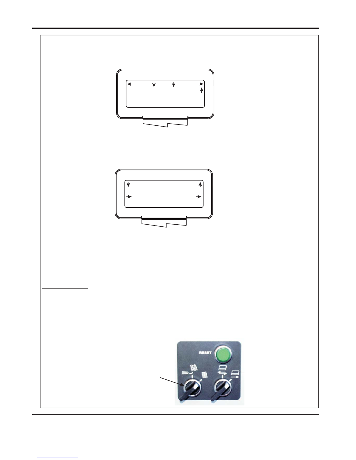
SYSTEM
Set Switch in
this Position
3 Sheet Book
Prog 3
Books 9
Reset
Setup
Tools
Feed
Hand Feed is On
Back
Select Tools
Set Blade Pressure
Using the Booklet Maker in Manual Mode (Hand Feed).
Single Sheet Booklet.
IMPORTANT.
1.
If producing a single sheet booklet without stitch it will be necessary to set the
Creasing Style to or or .
2. If the ‘Square Back System’ is installed with the Booklet Maker ensure that the switch
on the ‘Square Back System’ is set in the position shown below.
All Sheets Cover & Centre Cover Only NoneNOT
(i) From the Booklet Maker start up menu, move the selection switch to the
left to select .
(ii) Move the selection switch down, one click at a time, selecting
until is selected. If the display reads move
the selection switch to the right to change it to .
(iii) Feed the booklet sheets, by hand, into the infeed tray of the Booklet Maker.
The booklet sheets will automatically feed into the Booklet Maker and be
folded and stapled.
Tools
Select Tools
Hand Feed Hand Feed is Off
Hand Feed is On
Documaster
DocuMaster MK3
Page 34
CREASING / BOOKLET MAKING
Setting the Machine up as a Booklet Maker
Recognition Off
Recognition
Home
More
Cover (Sheet 1)
Cover (Sheet 1)
Cover (Sheet 1)
Sheet 2
Sheet 3
Sheet 4
Feed Bed
4 Sheet Booklet
Image To Be Captured Can Be On The
Underside Of Any Sheet Of The Book
Sheet 2
Sheet 3
Sheet 4
4 Sheet Booklet
TYPICAL BOOKLET STACK (FIXED DATA)
Sheet 2
Sheet 3
Sheet 4
4 Sheet Booklet
Using The Optional Camera Recognition System (If Fitted), and the number
of sheets in each book are the same. (i.e. Fixed Data)
Programme the machine for Booklet Maker operation as described on
pages 22 to 32, and then operate the Camera Recognition System as
follows:-
NOTE:-
(ii) Move the selection switch to the right, one click at a time, (selecting )
until the display contains the word .
More
Recognition
1. From the Booklet Maker start up menu, the camera can be set
as follows:-.
(i) Move the selection switch to the right to select .
Recognition
Setup
Page 35
SYSTEM
Recognition On
Recognition
Home
More
Back
Tens Decimals
Position: 90.0
Capture Image
Recognition
Location: (Cover) -
Back
Position: 90.0
Recognition
Location: (Cover) -
(iii) Move the selection switch down, (selecting ). If the display
reads , move the selection switch to the right to change
it to .
(iv) Move the selection switch down.
(vi) Move the selection switch down.
Recognition
Recognition Off
Recognition On
(v) The that contains the image to be captured can now be set by
rotating the Selection Switch, (clockwise to increase or anti-clockwise to
decrease).
(vii) The of the image to be captured (from the leading edge of the
sheet) can now be set as follows:Move the Selection Switch to the left to select or to the right to
select . The or (whichever has been selected)
can then be adjusted by rotating the Selection Switch, (clockwise to
increase or anti-clockwise to decrease).
The default position, (of the image capture position), from the leading edge of
the sheet is 90mm.
Page
Position
Tens
Decimals Tens Decimals
NOTE:-
Limitations of the position of the Image, to be captured, on the sheet.
DocuMaster MK3
Page 36
CREASING / BOOKLET MAKING
Setting the Machine up as a Booklet Maker
Back
Capture Image Now
Recognition
Leading Edge
Crease
90mm
+70 mm No Hinge
IMAGE TEMPLATE
90
100
120110 130 140 150 160 170 180 190 200 210 220 230 240 250 260 270
280
290
Camera Recognition Assistant
Paper Gate
Fixed Rear Lay Edge
Image Area
Part No. 70-113
90 mm
102.5 mm
7mm
3mm
Viewed From Underneath
Image Can Only Be
Within This Band
Of Sheet
+60 mm 10 mm Hinge
FIXED DATA
If there is no image on the sheet, at 90mm from the leading edge of the sheet,
then another position greater than 90mm must be set.
Limitations to the positions of the captured image are pre set in the software
and cannot be exceeded. See Below.
An Image template is provided with the camera recognition system kit to assist
in showing the possible area of the image that can be captured. The Template is
shown below.
(viii) Move the selection switch down.
(ix) Place the sheet, that has the required image, onto the feed bed with the
image face down.
(x) Press the Compressor Switch down.
(xi) Press the System Switch down.
Page 37
SYSTEM
OK
Image Capture
Completed
Cover (Sheet 1)
Sheet 2
Sheet 3
Sheet 4
Feed Bed
4 Sheet Booklet
Cover (Sheet 1)
Sheet 2
Sheet 3
3 Sheet Booklet
Cover (Sheet 1)
Sheet 2
Sheet 3
Sheet 4
5 Sheet Booklet
Sheet 5
TYPICAL BOOKLET STACK (VARIABLE DATA)
Image To Be Captured Can Only Be On The
Underside Of The Cover (Sheet 1) or Sheet 2.
(xii) Move the selection switch to the right to select .
The sheet will be automatically fed into the machine and the camera will
be activated to capture and store the required image.
(xiii) The display will show that the image has been captured, as shown below.
(xiv) Move the selection switch up, one click at a time, until the display contains
the word .
(xv) Load the booklet stack onto the feed bed; and then run the job by switching
the Compressor and System Switches on, and then move the selection
switch down to select .
Capture Image Now
Feed
Feed
Using The Optional Camera Recognition System (If Fitted), and the number
of sheets in each book are different. (i.e. Variable Data)
Do not use ‘Stream Feed’ when running variable data jobs.
NOTE:-
DocuMaster MK3

Page38
CREASING/BOOKLETMAKING
VariableData
Prog?
Books?
Reset
Setup
Tools
Feed
ImageRecOn
LeadingEdge
Crease
90mm
+70mmNoHinge
ImageCanOnlyBe
WithinThisBand
OfSheet
+60mm10mmHinge
-20mmNoHinge
-30mm10mmHinge
IfisSelected
Cover
IfisSelectedSheet2
ImageCanOnlyBe
WithinThisBand
VARIABLEDATA
1.ProgrammethemachineforBookletMakeroperationasdescribedon
pages22to32,settingthetoasdescribed
onpage25.
2.OperatetheCameraRecognitionSystemasdescribedonpages34to36.
Whentheselectionswitchismovedupuntilthedisplaycontainstheword
thedisplaywillreadasshownbelow.
3.Loadthebookletstackontothefeedbed;andthenrunthejobbyswitching
.theCompressorandSystemSwitcheson,andthenmovetheselection
switchdowntoselect.
SheetsinBookVariableData
LimitationsofthepositionoftheImage,tobecaptured,onthesheet.
Feed
NOTE:-
NOTE:-
Thedefaultposition,(oftheimagecaptureposition),fromtheleadingedgeof
thesheetis90mm.Ifthereisnoimageonthesheet,at90mmfromtheleading
edgeofthesheet,thenanotherpositiongreaterthan90mmmustbeset.
Limitationstothepositionsofthecapturedimagearepresetinthesoftware
andcannotbeexceeded.SeeBelow.
Feed
Page 39
SYSTEM
Perforating
Notes
Perforating ‘Spares’ kits
1. Perforating and creasing can be carried out simultaneously. However, if any
adjustment is made to the roller tilt mechanism in order to compensate for the
perforation line being ’out of square’, this may effect the accuracy of the crease. If
this occurs creasing and perforating must be carried out as separate operations.
2. By adjusting the outfeed drive tyres relative to the drive hubs it is possible to stear
the sheet, (i.e. By placing the tyre on top of the hub one side of the paper will stear
faster on that side).
Important: The perforator blades are very sharp and
care must be taken whilst handling.
Do not mix the matching pairs of blades or anvils.
Perforating blades 1-99-41
1-99-12
1-99-10
Anvils 1-99-35
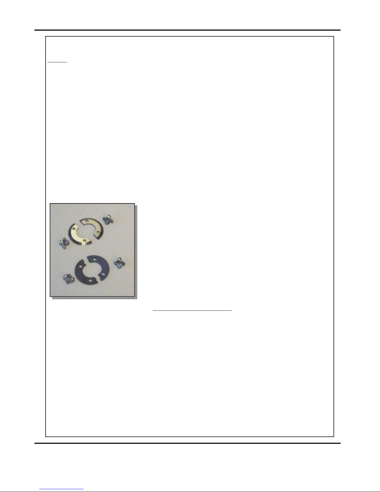
The components and tools required to install the perforator are contained in the despatch
kit supplied with the machine, they are listed below.
1 off Set of standard perforation ‘56 tooth’ blades.
1 off Set of standard hardened anvils.
1 off Perforator stripper.
1 off Scoring wheel
1 off 3mm bondhus wrench / allen key
1 off 2mm bondhus wrench / allen key
The perforator blades are split into two matching halves and
are fitted to the drive wheels as shown in the photograph
using the four screws supplied.
A hardened anvil is fitted to the drive hub as shown in the
photograph also using the four screws supplied. Again the
anvils are made from matching halves.
For perforating and other types of paper, various spares kits are available which can be
assembled to the machine in the same fashion. They are listed below along with a range
of scoring wheels,
56 teeth Part Number - Standard stock /
fine perforations.
28 teeth Part Number - Medium stock /
Medium perforations.
20 teeth Part Number - Heavy stock /
coarse perforations.
Standard Part Number - For all blade types
DocuMaster MK3
Once the machine is set-up, the Documaster Mk3 can be used to perforate or crease.
Page 40
Perforating
CREASING / BOOKLET MAKING
FIG 16.2
FIG 16.1
*Perforator stripper 78-013
All of the blades and anvils are supplied with fixings.
Standard Part Number
*It is recommended that for multiple perforations, a separate perforator stripper is used for
every perforating blade set fitted in the creasing unit.
1. Turn the mains supply to the machine ‘off’.
2. Remove the stacker unit and open the exit guard.
3. Locate and remove the blades / anvils from the despatch kit supplied with the
machine.
4. Using the 2mm allen key (supplied), loosen the drive wheel that is to accommodate
the blades.
5. Slide the drive wheel away from any obstructing drive wheels or hubs in order to
mount the blades.
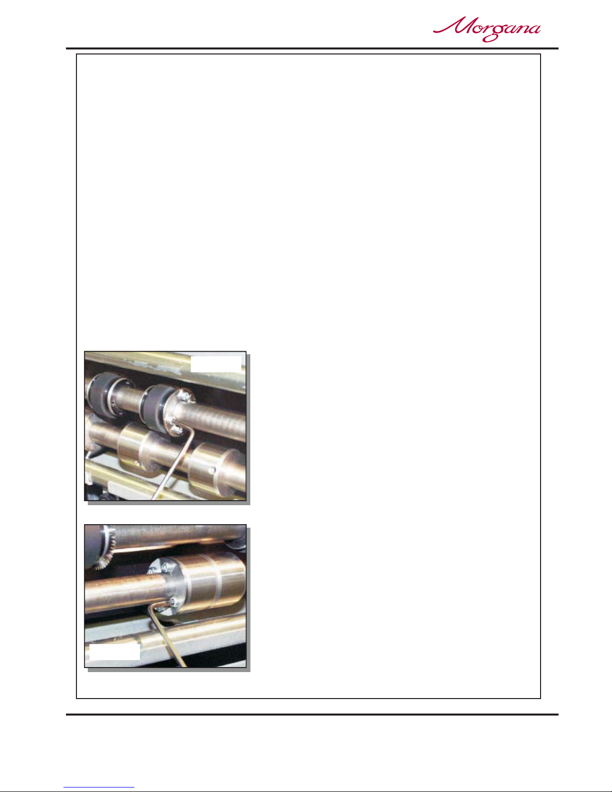
6. Using the 2.5mm allen key (supplied), take one
half of the matching pair of blades and mount on
to the drive wheel. Do not secure the blade.
7. Mount the other half of the blade to the drive
wheel as shown (fig 35.1). Secure the blades to
the wheel ensuring not to over tighten grub screw.
8. Mark on a single sheet the desired perforating
position. Feed the sheet through the machine
manually until the mark can be seen. Use this
mark to assist in fixing the position of the
perforating drive wheel to the roller drive shaft.
9. Using the 2mm allen key, loosen the drive hub
nearest the perforating drive. Slide the drive hub
away from any obstructing drive wheels or hubs
in order to mount the anvils.
10. Using the 2,5mm allen key, take one half of the
matching pair of anvils and mount to the drive
hub. Do not secure the anvil.
Setting the machine
Page 41
5
2
1
3
4
FIG 17.1
SYSTEM
Perforating
11. Mount the other anvil ensuring that they have matched on the drive hub. Secure the
anvil to the hub ensuring not to over tighten grub screw as shown in fig 16.2.
12. Slide the drive hub towards the perforating drive wheel until there is a clearance
of 0.5mm.
13. To prevent damage to the blades or the anvils, do not force the drive wheel against
the hub.
14. Fix the perforator stripper adjacent to the drive wheel and blade as shown.
15. Operate the machine and test the perforations for form.
For multiple perforations repeat the above procedure.
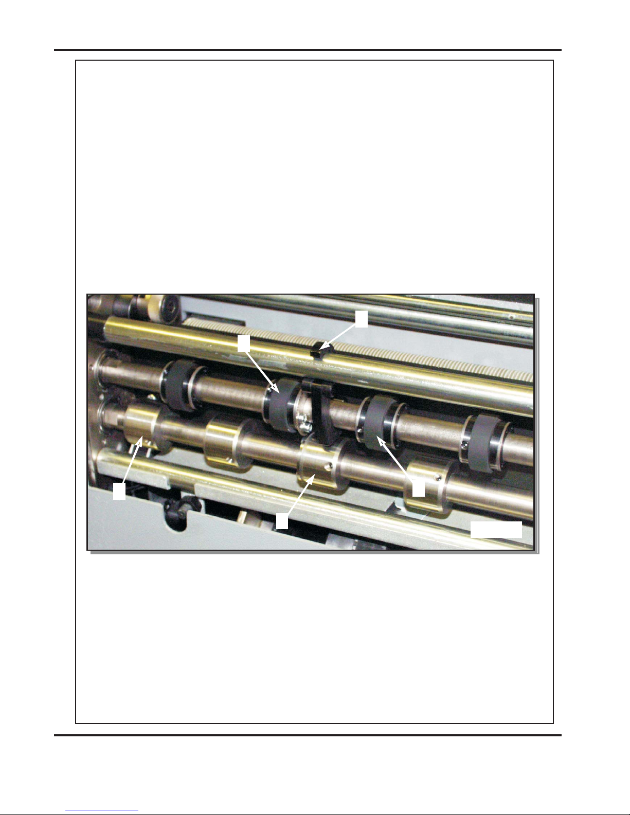
Demonstrates a typical set-up for perforating sheets.
- Perforating drive wheel with mounted blades - Drive hub with mounted anvils
- Perforator stripper - Standard drive hub
- Standard drive wheel
It is important that the drive hubs are arranged evenly across the width of the paper
in order to reduce the risk of jamming.
Fig 17.1
14
25
3
Always remove blades and anvils once the perforating operation has been
completed to avoid marking on digital or delicate media.
DocuMaster MK3

Page 42
The Blade Assembly
2 Creases
Program 3
To ta l 2 0
Zero
Setup
Tools
Feed
Batch Off
CREASING / BOOKLET MAKING
Tools
Set Blade Pressure
Blade is moving to TOP DEAD
CENTER Blade Pressure May Now Be Adjusted See
Operators Manual
Adjusting the blade pressure (no paper required)
1. (i) Switch the power ‘on’ by turning the Emergency stop button clockwise to release the
safety latch. The display is now switched on and will show the start up menu as
shown below.
(ii) Move the selection switch to the left to select .
(iii) Move the selection switch down to select .
(iv) Press the system switch down.
(v) Move the selection switch to the right, the machine will activate and the blade will
move to top dead center. The display will now read
and then change to read
.
2. Raise the exit guard
3. Using a 6mm allen key, unlock the shoulder bolts (labelled with scale transfer)
positioned at each end of the creasing blade.
4. Turn the adjustment cam to adjust the blade pressure. Increasing the gradient on the
scale will increase the blade pressure.
5. Ensure that the shoulder bolts are locked after setting.
The diagram below demonstrates the adjustment of the blade pressure
Page 43
The Blade Assembly
SYSTEM
Adjusting the blade alignment
It is extremely important that the blade and anvil assembly within the creasing unit is
correctly aligned. Misalignment of the blade or anvil can lead to damaged profiles and
subsequently poor quality creasing so it must, therefore, be corrected immediately.
If the blade set is misaligned, the media being driven will be subject to scoring or even
tearing at any point along the crease line.
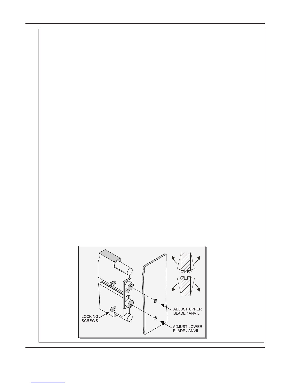
The below sketch
demonstrates how the blade alignment can be carried out.
Adjustment can be made at either of the blade or anvil. The two clearance holes positioned above the roller tilt mechanism are the front alignment (one for blade, one for anvil).
The two holes are repeated on the back of the machine for the back alignment.
1. Remove the stacker unit from the machine.
2. Unlock and centralise the roller tilt mechanism in order to locate the heads of the
front alignment screws.
3. Using a 3mm allen key, loosen the cap head type locking screws located on the
front face at both ends of the blade /anvil as shown below.
4. Using a 4mm allen key, locate the two front or back alignment screws in the side
frame in order to adjust the blade / anvil.
5. The upper screw of the two, will adjust the upper blade / anvil whereas the
lower screw will adjust the lower blade / anvil both in very small increments.
6. In order to obtain the required position, adjust either the blade or the anvil by a
small amount and then operate the machine to test the form of the crease.
Repeat the exercise until centralisation is located.
7. Using a 3mm allen key, lock the cap head type screws (as per step 3) on both the
upper and lower blade / anvil.
Please note that to avoid damage to the
blade set, adjustment should only be made in small increments.
DocuMaster MK3

Page 44
Replacing Blade Set
Blade Extractor Tools
FIG 20.1
CREASING / BOOKLET MAKING
1. Before removing the blade assembly, ensure that the lower blade / anvil is NOT
at ‘top dead centre’, Switch the machine off.
2. Remove the stacker unit and lift the exit guard.
3. Using a 6mm allen key, loosen the socket
head screws located inside the blade
adjustment cams. Remove the screws and
the blade adjustment cams.
4. Insert the blade extractor tools (70-055-01 &
70-055-02) into the holes in the adjustment
links, as shown. Push downwards on the
handles of the blade extractor tools to
release the blade assembly from the power
links.
5. Slide the blade assembly out of the creasing
unit and lay it on a flat surface.
6. Slide the adjustment links away from the
dowels located in the ends of the blades /
anvils as shown in the photograph (left)
7. Place the new blade set into position.
Check that the eccentric shoulder bolts on
the link plates have been positioned as
shown in fig 20.1.
8. (Upper blade / anvil only)
Slide the adjustment links onto the dowels.
9. Slide the new blade set into the slots of the
creasing unit as shown in fig. 21.1.
Locate the blade extractor tools into the holes in
the adjustment links as shown. Pull the handles
of the blade extractor tools upwards to engage
the blade assembly back into the power links.
10. Set the cam graphics for both ends of the blade /
anvil to their lowest point on the scale (ie. When
the mark on the scale reaches the mark on cam
holder) Fasten the socket head screws on the
adjustment cams until they are tight.

Page 45
Replacing Blade Set
FIG 21.1
SYSTEM
11. Push the exit guard down and replace the stacker assembly before operating the
machine.
12. Switch the machine on and test the crease for form.
In the event of any damaged or lost components within the blade assembly, spares kits
are available on request. However, components within the blade set can not be ordered
separately ie single blade or anvil.
Consisting of a standard blade and anvil, blade brushes, blade links and alignment bolts.
Consisting of a narrow blade and anvil, blade brushes, blade links and alignment bolts.
If the pressure and the alignment of the crease is not to a satisfactory level,
see pages 42 - 43 to adjust the creasing line.
Standard Blade set Part number 76-213-01
Extra Narrow Blade set Part number 76-213-03
‘Spares’ kits
DocuMaster MK3

Page 46
Trouble Shooting
CREASING / BOOKLET MAKING
Paper crease out of square
Paper jamming
Machine will not start
Paper not feeding
l Check that the sheets are all square and exactly the same size before loading the
stack on to the table.
Check that the roller tilt mechanism is correctly set and locked in position.
Check that the adjustable side lay has been correctly positioned ie. No further than
0.5mm from the paper stack.
Check that the leading edge of the paper is not being damaged by the paper gate. If
this is occurring, check that the suction slot and the paper gate have been correctly
set.
Check that the first crease position is not too close to the leading edge of the paper.
A minimum distance of 32mm is recommended.
Check the power supply to the machine.
Check that the emergency stop button has been released.
Check that the exit guard is down.
Check that the stacker unit is located correctly and has not been disconnected from
the magnetic switch.
Check that the lower blade / anvil is connecting to the home switch (mounted below
the lower blade / anvil).
Check that the paper stack is not too high or too heavy for the feeder. The height of
the paper stack should be defined by the weight and the size of the stock being
creased.
Ensure that the adjustable side lay is not pressed against the paper stack. However,
if the clearance between the adjustable side lay and the paper stack is too great, the
air supply will escape instead of blowing through the paper thus making it difficult to
feed.
Check that the clearance between the paper gate and the suction roller is not set too
low.
On digital media, the feeding performance may be improved if the leading edge of
the stack is trimmed before loading onto the machine.
l
l
l
l
l
l
l
l
l
l
l
l
l

Page 47
Trouble Shooting
SYSTEM
l
l
l
l
Check that the air distribution has been correctly set.
Check that the air separation has been set high enough to feed the sheets.
For heavy stocks, very small or very large sheets, embossed or even irregular stock,
it may be required to feed the sheets manually - see page 20 for instructions.
Open the exit and remove the blade set
(see pages 44-45) to access the dual
sensor post located in between the drive
rollers. Using a soft brush, clean the
visible sensor on the end of the post.
Use the brush to clean the sensors
between the post and the bottom paper
guide which are not visible.
Photograph (left) shows the dual sensor
post containing the sensors.
If the suction drum is not rotating, check all of the drive belts for cleanliness and
splits (including the bottom in-feed roller drive belt).
.
If at any time during the creasing process the control panel reads it
is indicating that the lower blade / anvil has not made contact with the HOME switch ie.
blade still in top position. Switch the machine off and remove the blade set and ensure
that the area is free from obstructions. Return the blade set to the creasing unit
and switch the machine on. Operate the machine in the normal sequence, if the
display continues to read it is advised to contact a Service Engineer
immediately.
If before operating the machine the display reads this
indicates that there is an obstruction between the upper sensor assembly and the
paper guide sensor (as shown in the above photograph). If there is no obvious
obstruction in the paper path, switch the machine off and repeat the same procedure as
explained above.
Machine not counting
No suction
Control panel reads
Blade Not Home
The Paper Path is not clear
l
l
Blade Not Home
Blade Not Home
The Paper Path is not clear
DocuMaster MK3

Page 48
Trouble Shooting
CREASING / BOOKLET MAKING
Recommended weekly operator maintenance
Technician Maintenance
• Clean all sensors
• Clean in feed rollers and output drive hubs using the cleaning kit supplied.
(Cleaning kit part number 90-018)
• Remove and clean the blade assembly
• With the blade assembly removed, clean the slots and surrounding area
within the creasing unit.
It is recommended that your machine is fully serviced at least once every six months
by a factory trained Service Engineer.
To
To
Re-register the Booklet Maker Unit.
Reset The Booklet Maker Unit Back To Factory Default Settings.
NOTE:-
The Booklet Maker Unit can be re-registered as follows:-
This function will adjust all motor settings to a known start position. It will also display the
version of software loaded into the Interface Module (housed within the motorised infeed unit),
and the version of software fitted on the Main Control board of the Booklet Maker Unit.
This will reset the Booklet Maker Unit back to default factory settings and should only be used
as a last resort.
1. From the Booklet Maker start up menu, move the Selection Switch to the left to select .
2. Move the Selection Switch down to select .
3. Move the Selection Switch to the right to select.
1. From the Booklet Maker start up menu, select move the Selection Switch to the left to .
2. Move the Selection Switch down to select
3. Move the Selection Switch to the right to select.
Minor sideways misalignment, caused by uneven floor or machine build tolerances, can be
adjusted as follows:-
1. From the Booklet Maker start up menu, move the Selection Switch to the left to select .
2. Move the Selection Switch down to select .
3. Rotate the Selection Switch to adjust, a positive value will move the Creaser Unit away
from the operator.
Values of less than 3 may not be enough to adjust the position.
Tools
Re-register BMP
Tools
Set BMP ‘DEF’.
Tools
BMP Alignment
To Adjust Misalignment Between Creaser Unit and Booklet Maker Unit.

Page 49
SYSTEM
Error Messages
‘Warning Sheets not cleared from Bookmaster infeed’
‘BookMaster Error’
‘Double Sheet Feed - Detected’
‘Bookmaster Error - Trim Out Of Range’
‘Warning Vario Trim Guard Open’
‘Warning Vario Stitch Guard Open’
‘Warning Sheet Failed to Arrive’
‘Bookmaster Error - Bad Status Response’
‘Warning Image Out of Sequence’
‘Warning Vario Jam Detected’
Remove sheets from the infeed tray of the Booklet Maker.
Check all Doors and Access Panels are shut correctly
Check Mains Power is Switched on and also Communication Cable is Plugged in.
Check Waste Bin is Empty.
Remove any sheets from the infeed tray of the Booklet Maker and also the Suction Drum area.
Ensure integrity of the remaining booklets in the feed stack.
Check that the trim length is less than half the sheet length.
If no Spinemaster (Square Back) is in line, check that the bridge plug is in place.
Check that the Stitch Guard is shut correctly
Check paper feeding is adjusted correctly, (see page 46).
Check yellow light on Booklet maker (see Booklet maker operators manual
70-114).
Check number of sheets is set correctly.
Check image is captured correctly, reset if necessary.
Check Booklet maker for jams and remove (see Booklet maker operators manual
(70-114).
DocuMaster MK3

DISPATCH KIT
ITEM PART NUMBER QTY DESCRIPTION
1
1 OPERATORS MANUAL(Part 1) (Creasing Unit)
3 90-018 1 ROLLER CLEANING KIT
4
5
650-040 1 POWER CORD
C19-3Pin-UK
650-016 1 L6 - 15P Re-Wirable Plug (Used on USA Only)
11
12
13
620-028 1 BONDUS L WRENCH 3mm
16
620-033 1 BONDUS L WRENCH 6mm
14
624-018 1 DISPATCH BOX
9
620-007 1 HEXAGON BALL DRIVER 2mm
620-026 1 BONDUS L WRENCH 4mm
620-020 HEXAGON BALL DRIVER 2.5mm
10
1
15
70-055-01 1 BLADE EXTRACTION TOOL - OP SIDE
70-055-02 1 BLADE EXTRACTION TOOL - LAY SIDE
WARNING......
THE BLADES FOR ANVIL AND PERFORATING SETS ARE SUPPLIED AS
MATCHING PAIRS AND SHOULD NOT BE MIXED OR LEFT
UNPROTECTED OR SERIOUS DAMAGE MAY RESULT.
8
17
94-087-01 1 CLAMP PLATE - SIDELAY
18
94-087-02 2 CLAMP PLATE WIDE - SIDELAY
7
2
1 OPERATORS MANUAL
(Part 2) (Booklet Making Unit)
650-041 1 POWER
C19-3Pin-USACORD
6
617-004 4 GLASS BALL - Ø20
7-99-01 1 ANVIL SET - Perforator
1-99-12 1 PERFORATOR BLADE SET - 28T
Page 50
CREASING / BOOKLET MAKING
70-114
70-111
7-95-13

ITEM PART NUMBER DESCRIPTION
ACCESSORIES AND OPTIONS
1-99-10 PERFORATING BLADE SET 20T (Card)1
1-99-12 PERFORATING BLADE SET 28T (Single sheets)2
1-99-41 PERFORATING BLADE SET 56T (Fine perforations)3
1-99-35 ANVIL SET USED WITH ABOVE BLADE SETS4
76-213-03 BLADE SET - EXTRA NARROW5
Page 51
SYSTEM
79-052-01 FA45 OBJECT CAMERA KIT6
ACCESSORIES.... OPTIONS....
....May be obtained from ....May also be obtained and
your dealer and fitted to your fitted by your dealer. You should
machine using the instructions not attempt to fit options as
supplied, or by reading your specialist tools and knowledge are
operators manual. required.
75-407 ETHERNET KIT7
DocuMaster MK3
RECOMMENDED SPARES
PART NUMBER DESCRIPTION
93-021 FEED BELT
93-022 DRIVE BELT - Vacuum Roller
609-011 ‘O’ RING Ø20
609-014 ‘O’ RING Ø15
94-028 LOCK PIN ASSEMBLY - Side Lay
75-365
75-366 HOSE - Vacuum Blow
75-367 HOSE - Separation Air
HOSE - Vacuum
613-137 PLUNGER AND SPRING
613-255 SOLENOID COIL
609-013 ‘O’ RING Ø25
613-365 EMERGENCY STOP SWITCH
652-011 SYSTEM SWITCH
75-378-01 DOCUMASTER CONTROL PCB ASSY + CHIP
125-21-02 DUAL STEPPER DRIVE PCB ASSEMBLY
655-011 PSU UNIT 5V/24V
655-015 PSU UNIT - SWITCH MODE - 24V
76-230-03 PAPER GUIDE ASSEMBLY - Bottom Sensor
76-242 PAPER JAM SENSOR ASSEMBLY
76-154 UPPER SENSOR ASSEMBLY
98-013
ANTI-STATIC BRUSH
609-022
‘O’ RING Ø32
606-035 KNOB - Roller Tilt
76-109
POWER LINK BEARING
76-213-01 BLADE SET - Standard
76-042 DRIVE BELT - FEED BED
607-042 TIMING BELT 160XL
607-048 TIMING BELT TWIN GRIP - 200 DXL 050
608-019 SHOULDER BOLT
75-352 POT & LEAD ASSEMBLY
652-009
75-210-05 LCD DISPLAY UNIT-4LINE
144-04-02 JOYSTICK AND LEAD ASSEMBLY
652-010
COMPRESSOR SWITCH (UK)
COMPRESSOR SWITCH (USA)
655-016 PSU UNIT - SWITCH MODE - 48V
76-156 BLADE POSITION SENSOR
Page 52
CREASING / BOOKLET MAKING

RECOMMENDED SPARES
PART NUMBER DESCRIPTION
76-175-01
INPUT ROLLER - Lower
76-177-01
INPUT ROLLER - Upper
76-250-01
UPPER OUTPUT SHAFT ASSY
613-351 MICRO SWITCH - Guard Circuit
613-191 MICRO SWITCH - Home Circuit
78-071-01 ACTUATOR ASSY. - STACKER
602-056 BEARING-DRAWN CUP NEEDLE ROLLER - Ø15XØ21X12
602-085 BEARING-DRAWN CUP NEEDLE ROLLER - Ø10XØ14X10
PERFORATOR STRIPPER ASSEMBLY
78-013
78-251-01
LOWER OUTPUT SHAFT ASSY
613-023
681-011
FUSE 3.15A - Fast Blow
FUSE 315ma - Anti-surge
FUSE 4A - Anti-surge
681-015
175-082-01
RELAY PCB Assy
INTERFACE CABLE
75-388
76-042
DRIVE BELT - FEED BED - Polycord
STACKER SWITCH Assy
75-040
654-014
ULTRASONIC RECEIVER
ULTRASONIC TRANSMITTER
654-015
626-004
STATIC ELIMINATOR BAR
ANTISTATIC TRANSFORMER
75-258
610-029
DOGA MOTOR
Page 53
SYSTEM
NOTE.....
The items listed above represent parts which are subject to wear, loss, or accidental
damage, and is included for your guidance only.
Replacement of parts fitted to your machine require specialist knowledge and should
therefore be entrusted to your dealer.
DocuMaster MK3

Page 54
CREASING / BOOKLET MAKING
MACHINE CALIBRATION HISTORY
Stretch
Lead Edge Trim
Width Trim
Date:-
Total Count:-
Serial Number:-
Camera Fitted

Page 55
SYSTEM
PRODUCT RECYCLING & DISPOSAL
European Union
Disposal Information for Commercial Users
Disposal Information for Domestic Users
Other Countries
DocuMaster MK3
 Loading...