


90-134 Issue 3 FEBRUARY 2013
DocuFold Pro (CB/UL)
OPERATORS MANUAL
Automatic Paper Folding Machine
Morgana Systems Limited United Kingdom www.morgana.co.uk Telephone: ( 01908 ) 608888 Facsimile: ( 01908 ) 692399

Page 2
INDEX
INTRODUCTION & SPECIFICATION PAGE 4
SAFETY Do’s & Don'ts 5
THE DocuFold Pro
Labelled Photograph 7
OPERATING THE DocuFold Pro
Adjusting the Paper Gate 8
Setting the Suction Slot 8
Setting the Vacuum Bleed 9
Setting the Adjustable Side Lay 9
Setting the Back Stop 9
Setting the Air Distribution Knob 9
Setting the Air Separation Knob 9
Fold Plates 10
Roller Tilt 11
Delivery Roller 12
Emergency Stop Switch 12
Overlap 12
TOUCHSCREEN OPERATION
Touchscreen Layout 13
Paper Settings Page 14
Batch Size selection 15
Speed Selection 15
Fold Settings Pages (Pre-defined fold types) 16
Setting Fold Positions Manually (Set by Position) 17
Delivery Settings Pages 19
Status Screen 20
Run Job 21
Store Pages 23
Tools Menu 26
Touch Screen Calibration 27
PLUG IN PERFORATOR 28
Setting Perforators 31
Scoring 31
Folding Card 32
Paper Jams 32
Roller Assembly - Removal 32
Roller Adjustment 33
Sensor Cleaning 34
Fold Plates - Maintenance 34
DocuFold Pro
PAPER

Page 3
INDEX
FOLDING TIPS AND TROUBLESHOOTING 35
Sheets Difficult To Feed 35
Double Sheet Feeding 35
Fold Is Not Square Or Consistent 35
Paper Will Not Stack Consistently 36
Paper Will Not Deflect When Using One Fold Or Perforating 36
Total Batch Counter Not Working 36
‘Overlap Error Keeps Appearing 36
Machine Will Not Reset 36
No Power To Machine 37
Mains Switch Cuts Out 37
Fold Roller Replacement 37
ERROR SCREENS 38
DISPATCH KIT 41
ACCESSORIES AND OPTIONS 42
RECOMMENDED SPARES 43
FUSE POSITIONS & RATINGS 45
PRODUCT RECYCLING AND DISPOSAL 46
DocuFold Pro
FOLDER

Page 4
DocuFold Pro
The Morgana Docufold Pro is a brand new concept automatic paper folding machine
designed to be used in today's environment of document production. The Morgana
DocuFold Pro can be used by non-skilled personnel by following this easy to use operator's
guide. There are very few operator adjustments required and in conjunction with our new
'Smart screen' you will get started very quickly, but we do recommend that you take a little
time to read this manual, to ensure that you fully understand the machine. We have also
included a TIPS & TROUBLE SHOOTING section. Be sure to read this section before
calling a service engineer to avoid any unnecessary expense.
On the DocuFold Pro. The fold plates and delivery roller will move automatically according
to the type of fold selected. Please be aware that different weights, humidity, temperature or
the grain direction of the paper may make the paper fold in a different position according to
the material.
Some manual adjustment may sometimes be necessary to obtain the exact fold plate
position for each type of paper.
IMPORTANT
The operating environment should be controlled to a temperature between
16° C and 27° C Maximum
Specification
Feeding System ................................................ Bottom suction feed
Max. Sheet Size ................................................674mm x 365mm (26.5” x 14.4”)
Min. Sheet Size (in automatic mode)................. 160mm x 140mm (6.3” x 5.5”)
Max. Paper Weight ........................................... 240gsm Max. (0.24mm thick) according to
hardness, type of fold, grain direction and substrate
Min. Paper Weight ............................................ 56gsm (0.08mm thick)
Max. No. Folds per Sheet ................................. 2
Max. Fold Length long plate.............................. 328mm (12.91”)
Max. Fold Length short plate............................. 225mm (8.85”)
Max. No. Stored Programmes .......................... Unlimited
Speed per Hour (A4 Material) ............................27500 sheets (Stream Feed)
17250 sheets (Pulsed Feed)
Speed per Hour (A3 Material) ............................18000 sheets (Stream Feed)
13250 sheets (Pulsed Feed)
Note: The production speed varies according to the material size.
Dimensions ....................................................... L: 1240mm H: 1370mm W: 555mm
L: (48.8”) H: (53.9”) W: (21.8”)
Weight ...............................................................132Kgs (+50Kgs packing)
Power Requirement .......................................... 1 phase 230v 50Hz
1 phase 220v 60Hz
Sound Power Level .......................................... 96.0 decibels
*As part of our continued product improvement plan, specifications and information
published in this manual are subject to change without notice.
All specifications are dependant on application, type of stock, temperature, RH and print
engine used.
Specifications quoted were measured on uncoated and unprinted stock. E & OE.
Docufold Pro
INTRODUCTION

Page 5
DocuFold Pro
Safety Do’s & Don’ts
Do - read this operator manual fully before operating the machine.
Do - operate with the designated AC current only. Use an exclusive outlet, as
overloading may cause fire or an electric shock.
Do - install the power cord out of the way to avoid a tripping hazard.
Do - make sure that the mains inlet connector is always easily accessible.
Do not - install the machine in an unstable place such that it tilts or shakes.
Do not - unplug the plug or unplug the power cord from the outlet with a wet hand,
this can cause an electric shock.
Do not - unscrew and remove any covers from the machine, as it can cause an
electric shock or injury.
Do not - place receptacles containing liquids on any surface.
Do not - adjust any part of the machine whilst rollers are running
Do not - operate the machine with loose or trailing clothing or loose hair.
Do not - under any circumstances adjust the paper gate when the machine is
switched on.
REGLES DE SECURITE : « A FAIRE » ET « A NE PAS FAIRE »
Lire ce mode d'emploi avant d'utiliser la machine.
Respecter l'alimentation électrique indiquée. Brancher sur une prise séparée
car une surcharge peut entraîner un incendie ou un choc électrique.
Installer le cordon d'alimentation de manière à ne pas pouvoir
trébucher par dessus.
Ménager un accès libre à la prise de courant.
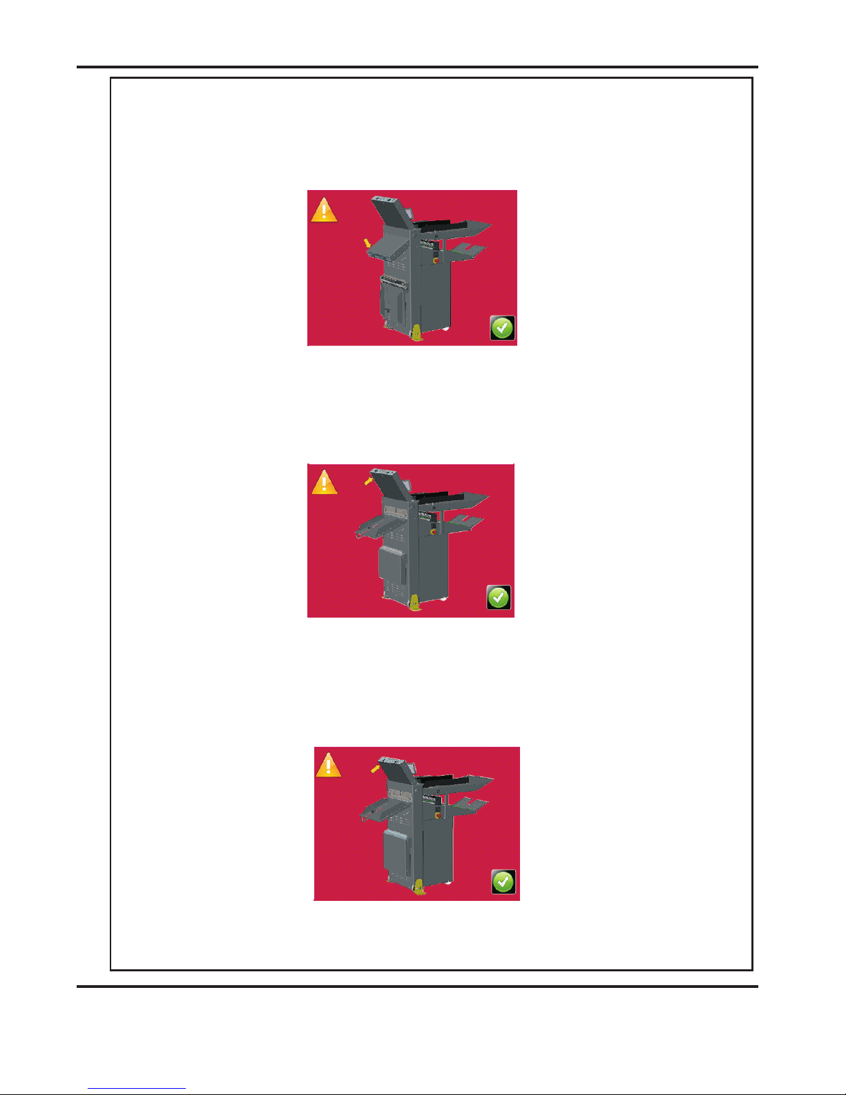
Do - Fit the yellow outrigger feet, (supplied in the Dispatch Kit), to the front and back
of the machine as shown on Page 7; to comply with safety regulations.
Fixer les pieds stabilisateurs jaune, (fourni dans le kit d'expédition), à l'avant et
l'arrière de la machine comme indiqué sur la page 7; pour se conformer aux
règlements de sécurité.
Ne pas installer la machine sur une surface non plane, afin d'éviter
qu'elle ne penche ou ne vibre.
Ne pas installer la machine sur une surface non plane, afin d'éviter
qu'elle ne penche ou ne vibre.
Ne démonter et enlever aucun carter de la machine, par crainte de décharge
électrique ou de blessure.
Ne pas placer de récipient contenant un liquide sur la machine.
N'effectuer aucun réglage pendant que les rouleaux fonctionnent.
Ne pas porter de vêtements flottants et rassembler les cheveux longs
lors de l'utilisation de la machine.
En aucune circonstance, régler le séparateur de papier lorsque la
machine est branchée.
Safety Do’s & Don’ts
Page 6
DocuFold Pro
PAPER
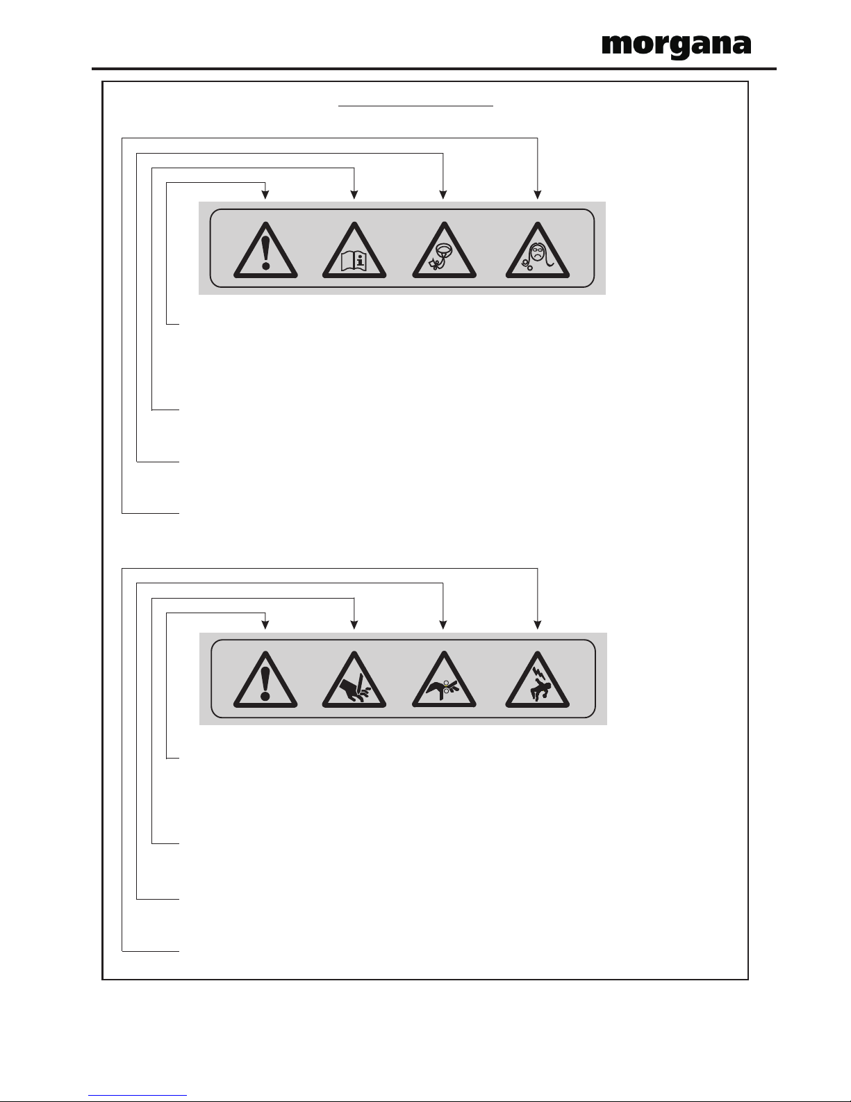
Warning Labels
Do - be aware of any finger traps and rotating parts when operating
the machine.
Do - read this operator manual fully before operating the machine.
Do not - operate the machine with loose or trailing clothing.
Do not - operate the machine with loose hair.
Do - be aware of any finger traps and rotating parts when operating
the machine.
Do - be aware of sharp points and blades.
Do - be aware of rotating rollers.
Do - be aware of low current anti-static shock.
Attention au risque de se coincer les doigts, et aux pièces en
mouvement lors du fonctionnement de la machine.
Ne pas porter de vêtements flottants lors de l'utilisation de la machine
Rassembler les cheveux longs lors de l'utilisation de la machine.
Attention au risque de se coincer les doigts, et aux pièces en
mouvement lors du fonctionnement de la machine.
Attention aux éléments tranchants et aux couteaux.
Attention aux rouleaux en fonctionnement
Attention aux faibles chocs d'électricité statique
Lire ce mode d’emploi avant d’utiliser la machine.
Page 7
DocuFold Pro
FOLDER
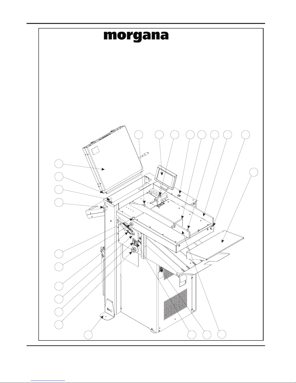
AUTOMATIC PAPER FOLDING MACHINE
Key to drawing below
A Moving side lay knob H System switch R Roller Tilt lever
B Paper gate knob J Front pins S Emergency stop switch
C Suction slot knob K Upper fold plate T Compressor switch
D Air distribution knob L Vacuum bleed knob U Extension table
E Air separation knob N Delivery roller V Fixed side lay
F Back Stop P Lead screw X Fuses
G Moving side lay Q Touch screen Y Roller assy. release knob
Z Outrigger Foot
Docufold Pro
J
A Q B E
F A
V
D
U
G
K
H
S
T
N
P
L
C
Y
R
X
Z
PAPER
DocuFold Pro
Page 8
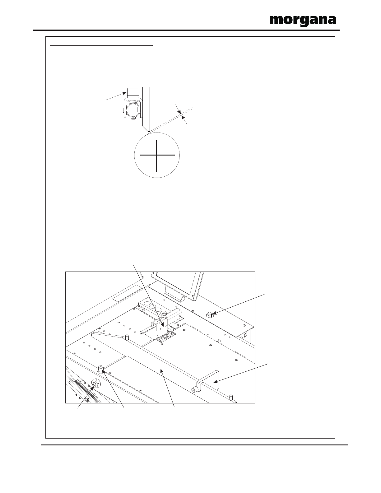
ADJUSTING THE PAPER GATE
Adjust the height of the paper gate using knob (B) (clockwise to lower, anti-clockwise to raise) so
that the clearance above the vacuum roller is two thicknesses of the paper to be folded. Do not
make this adjustment, when the face of the paper gate is above a hole in the vacuum roller, if it is,
rotate the vacuum roller by hand to bring the metal between holes below the paper gate.
On this machine, the paper gate is fixed in an optimum position and cannot be moved backwards
and forwards (horizontally).
SETTING THE SUCTION SLOT
The suction slot inside the suction drum, may be adjusted by releasing knob (C) and swinging the
knob in the desired position. Lighter stocks including bond will run best with the knob set to the
left. For heavier stocks and curled-up stock, move the knob (C) to the right until a satisfactory
position is obtained.
TWO THICKNESSES
OF PAPER
WARNING.
DO NOT ADJUST THE
PAPER GATE WHILE THE
MACHINE IS RUNNING OR
THE SUCTION DRUM MAY
BECOME DAMAGED.
B
Adjustable
Side Lay
Suction
Slot Knob
Vacuum
Bleed Knob
Air Seperation
Knob
Back Stop
Paper Gate
Operating the DocuFold Pro
Page 9
FOLDER
DocuFold Pro
Operating the DocuFold Pro
SETTING THE VACUUM BLEED (L).
Situated on the front of the feed table, the Vacuum Bleed Knob is used to allow more control of the
suction on the vacuum drum.
When light weight paper of 90gsm and lower is being fed through the machine turn the knob
clockwise to reduce the possibility of marking, or damage to the leading edge of the paper.
SETTING THE ADJUSTABLE SIDE LAY
Place a single sheet of the job onto the loading table.
Release the side lay clamp screws (A) and slide the side lay just up to the sheet so that there is
about half a millimetre clearance or 1/64 inch
Tighten the clamp screws.
SETTING THE BACK STOP (F)
This is placed up to the end of the paper stack and clamped to the moving side lay (G).
SETTING THE AIR DISTRIBUTION KNOB (D)
Depending on the length of the sheet, the air distribution knob (D) should be rotated to supply
the air to the correct ports as follows -
Position 1 - This is for short sheets A5 or 8" long with only port 1 open.
Position 2 - This is for sheets A4 or 11" long with the front port and port 2 open.
Position 3 - This is for the longest sheets A3 or 17" with the front port and port 3 open.
Position 0 - In this position, only port 2 is open and can be used on long sheets
with the curl up where you need to blow air into the centre of the stack.
These setting positions are only a guide and some experimentation may obtain a better result
with non-standard settings.
(Note) Position 1 feeds most paper stocks and sizes; thus the air distribution knob can be
left in this position for most jobs.
SETTING THE AIR SEPARATION KNOB (E)
This knob controls the amount of air that is fed to the paper. The machine would normally run
with this knob set at the 'High' position. If the machine is run with less than approximately 20
sheets on the loading table, or running the job to the last sheet, this knob should be set to the low
position.
Port 1
Port 3
Knob
Air Distribution

Page 10
Operating the DocuFold Pro Operating the DocuFold Pro
DocuFold Pro
FOLD PLATES
ALWAYS UNPLUG POWER CONNECTIONS BEFORE REMOVING FOLD PLATES.
Fitting
Fit the fold plates into their respective positions (long fold plate upper and short plate lower), by
locating the front pins (J) into the long slots and carefully sliding forwards (without twisting)
until the rear pins can be located into the short slots. When fully in position, pull down the fold
plate to lock into position. Connect the push-in power connectors - short lead to upper plate & long
lead to lower plate.
Settings
The fold plate lengths are set automatically.
Fold plate Tilt
See roller tilt.
IMPORTANT NOTE:-
If any of the fold plates, or the plug in perforator unit are removed from the machine; the
guard circuit is automatically broken, for safety reasons, to prevent the fold rollers from
rotating.
Page 11
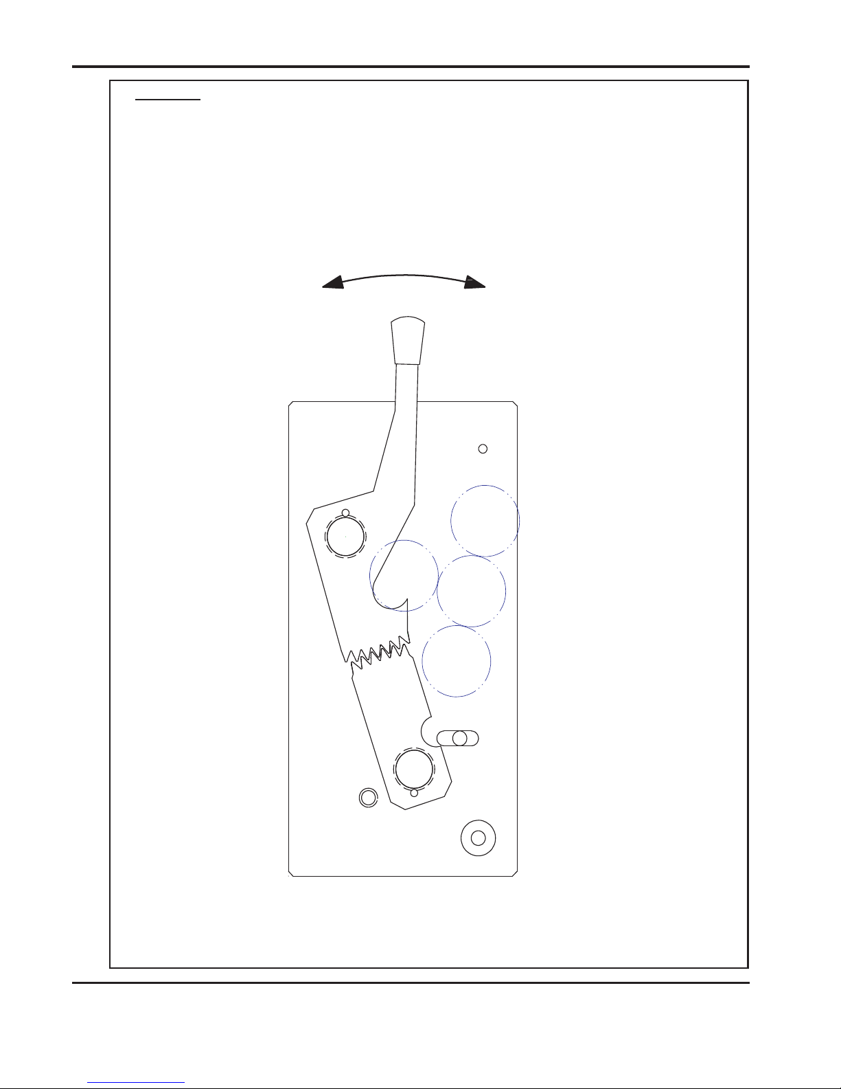
Roller Tilt
+
-
Lever (R) should always be set in the ‘0’ (square) position. To adjust folding
out of square you can move the roller assembly in the + or - direction by releasing
knobs (Y) and moving lever (R) - always re-tighten Knobs (Y)
DocuFold Pro
Page 12
Operating the DocuFold Pro Operating the DocuFold Pro
Delivery Roller
Emergency Stop Switch (S)
This switch also serves as the main isolator. It is important that the machine is switched off at
the end of the days running, press this switch to isolate the machine. To switch back on,
rotate the switch head clockwise.
The delivery roller will adjust automatically according to the paper length and the fold type selected.
Manual or fine adjustment for the position of the delivery roller can be made as shown on Page 19.
You should adjust the roller position so that when the work is stopped by the delivery roller, it
lies flat on the delivery without lying on the sloping plate, (See Diagram below), and without the
green belts showing between the sloping plate and the folded sheet.
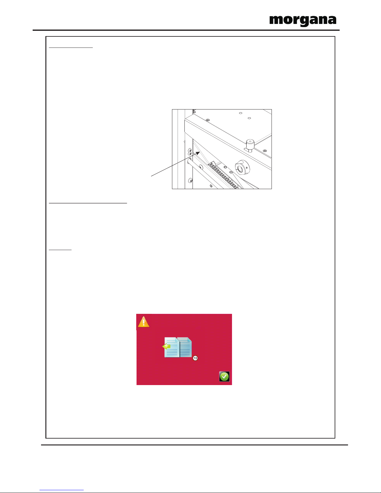
Overlap
The machine has a built in system that will detect any sheet that overlaps another sheet by at
least 20mm. When this happens feeding will stop and the main switch will switch off,
preventing serious jams. The error screen (shown below) will be displayed on the touchscreen..
Note that this is not a double detector and will not detect all double sheet feeds. However the
overlap system is an indication of a tendency to double sheet feed and therefore the paper gate
should be lowered slightly and the paper stack should be fanned out more thoroughly.
Sloping plate
DocuFold Pro

Page 13
TOUCHSCREEN OPERATION
1. Turn the Emergency Stop button clockwise to switch the power on. After the
system start up procedure the touch screen will be displayed as shown below.
WARNING:-
Wait at least 10 seconds, after making any selection on the Touchscreen
panel, before switching the machine OFF. Failure to do so could result in the
data storage being corrupted, and the machine not operating.
The touch screen is laid out into 3 main areas as shown below:
IMPORTANT.
If you have not been trained to operate this machine, we strongly advise that you select
the red cross icon.
We recommend that you either seek training or ask a trained operator to run the machine
for you.
Select the green tick icon only if you have been trained to operate this machine.
If you have not been trained to operate this machine and you select the green tick icon,
Morgana Systems Ltd accept no responsibility for personal injury, damage to the
machine or damage to materials being processed by the machine.
DocuFold Pro
Status of
machine
&
data entry
area. Also
used for
quick links
to setting
pages.
Tabs to enable switching between setting
pages
-
choose either Paper
Settings, Fold
Settings, Delivery Setting, Store or Tools
Setting
page

Setting Pages.
Paper settings Page
Paper size Selection.
Page 14
DocuFold Pro
PAPER
Operating the DocuFold Pro Operating the DocuFold Pro
DocuFold Pro
Page Length – On selection the status area is replaced with a
calculator for inputting new values. Length range = 190mm – 900mm
Fold Selection – For quick setting of crease positions on standard size sheets.
Highlighted fold is type currently selected, other folds may be selected.
Currently selected fold is shown in status area.
Select the Ruler icon to set the fold positions manually.
Vacuum suck – There
are three selections
available – 1 short
suck, 2 long suck & 3
continuous for stream
feeding.
Highlighted number is
type currently selected.
The status area also
shows the currently
selected suck.
Batch Button – Image
is identical to that
shown in the status
area. On selection the
status area is replaced
with a calculator for
inputting new values.
Batch sizes of 1 to
998 may be set.
Arrows may be
selected to increase
or decrease the page
size in 0.1mm
increments.
Perforating / scoring
button.
Speed Selector – On
selection a speed
adjustment screen
will appear.
Perforating / scoring
with fold button.
Toggle between, Delay between batches
and stop after batch
Pre-set Paper sizes for
quick insertion - Standard
sizes for country origin
would be shown.
Paper length input
Page 15
DocuFold Pro
FOLDER
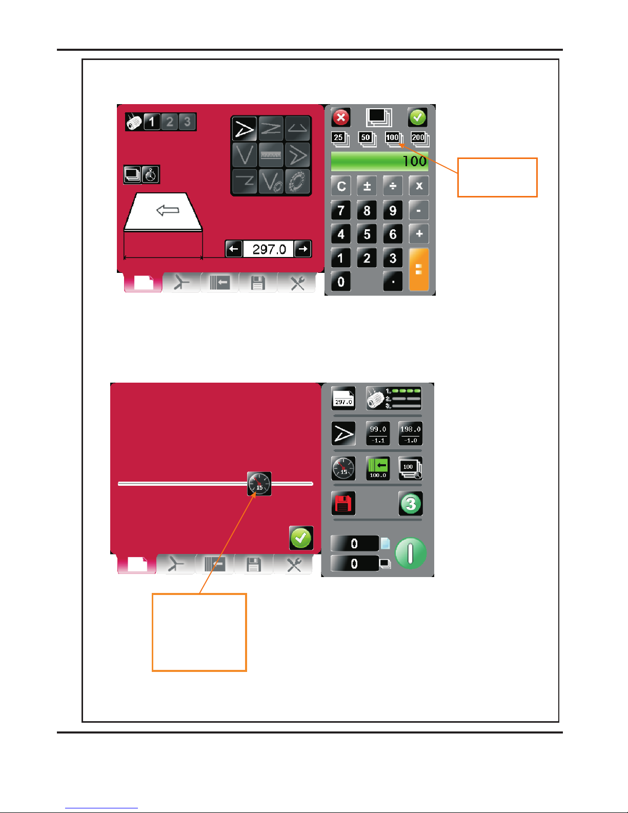
Batch size Selection.
Speed Selection
Pre-set Batch sizes
for quick insertion.
DocuFold Pro
Feed Speed selection
slider - 20 positions to
choose from.
Note: Motor speed will
not change until you
select run.

Page 16
DocuFold Pro
PAPER
Fold Settings Pages.
To get to the Fold setting page click the lower tab .
Pre- defined Standard Folds.
If you have selected a pre-defined standard Fold Type from the paper settings page the
recommended fold positions will be shown in parenthesis and can be micro adjusted as
required.
Fold 1 micro adjust – On
selection the status area is
replaced with a calculator
for inputting new values.
Micro adjust range is -5.0
to +5.0 with increments of
0.1mm
Folding can be micro
adjusted for fine
adjustment.
Micro adjust range is -5.0
to +5.0 with increments of
0.1mm
Operating the DocuFold Pro Operating the DocuFold Pro

Page 17
DocuFold Pro
FOLDER
Setting Fold Positions Manually (Set By Position).
If you have selected the Ruler Icon from the paper settings page the fold positions can be
set manually.
EXAMPLE 1. (Set Fold 1 to 210.0, Set Fold 2 to 90.0)
Paper Length = 297.0mm
Feed Direction
Fold 1
Fold 2
Fold 1 = 210.0mm
Fold 2 = 90mm
All dimensions are from the leading edge of the paper
Fold 1
= 210.0
Finished Document
Leading Edge
SETTINGS
Leading Edge
Fold 2
= 90.0
(on delivery bed)

Page 18
Operating the DocuFold Pro Operating the DocuFold Pro
Roller position may be
Micro adjusted by clicking
Here.
Roller adjustment
calculator
EXAMPLE 2. (Set Fold 1 to 90.0, Set Fold 2 to 210.0)
NOTE.
When only one fold is required on the sheet, set Fold 1 and Fold 2 to the same values.
Paper Length = 297.0mm
Feed Direction
Fold 2
Fold 1
Fold 1 = 90.0mm
Fold 2 = 210mm
All dimensions are from the leading edge of the paper
Leading Edge
SETTINGS
Fold 1
= 90.0
Finished Document
Leading Edge
Fold 2
= 210.0
DocuFold Pro
Morgana Logo
on underside of this flap
(on delivery bed)

Page 19
Delivery Settings Pages.
To get to the Delivery setting page click the lower tab .
Roller position may be
Micro adjusted by clicking
Here.
Roller adjustment
calculator
DocuFold Pro

Page 20
DocuFold Pro
Operating the DocuFold Pro Operating the DocuFold Pro
Status Screen.
Clicking in this area will take
you to the fold settings
page.
Paper length
- input from the
paper setting screen.
Clicking in this area will take
you to the delivery setting
page.
Fold Positions & Trim
settings
Batch quantity - this is
input from the batch
calculator on the paper
setting screen - max. 999
Click to start machine with settings currently
shown - you will receive a notification if
system switch is not on. Press again to stop
Job
Green icon indicates settings
are saved - a red icon would
show that settings have
changed but the job
has not been saved.
Currently selected fold type
- can be one of the
following.
Speed selector - On
selection a speed
adjustment screen
will appear
Currently selected Vacuum
Suck setting - for slow pulse
- for stream feed choose
choose selection 2
selection 3
Select this button to produce
3 test sheets with the
settings currently shown.
Clicking in this area will take
you to the store page
confirm that you want to
Sheet count -click to zero
A screen will appear to
reset the count.
Batch count - click to zero
A screen will appear to confirm that
you want to reset the count.

Page 21
DocuFold Pro
Run Job.
System Switch Not On, warning.
The display will briefly show that the fold plates and delivery roller are moving to their set
positions, (as shown below).
Click to run machine.
Click to confirm System
switch is on. Switch
Compressor switch on &
then click run button again.
Or click the icon
to run three test sheets.

Page 22
DocuFold Pro
Operating the DocuFold Pro Operating the DocuFold Pro
The machine running screen will appear.
NOTES:-
1. The folds can be micro adjusted from the run screen, if necessary, while the job is still
running.
2. The speed can also be adjusted from the run screen, while the job is still running.
Run count
Batch Count
Sheet Count
Click to stop machine.
Batch Count

Page 23
DocuFold Pro
Store Pages.
To get to the Store setting page click the lower tab or from the
status area.
New Jobs.
Having set up your job you can give the job a name and save it to a store. You can
also retrieve previously saved jobs, modify them or delete jobs you no longer require.
Keyboard for entering job name.
Return to Store Menu &
click save icon to save
job to store
To create a new job name click in text area &
keyboard will open to input job name.
Load existing job from
store
Clicking to search
currently stored jobs
Clicking to delete
currently stored jobs
Clicking to save job
shown.
Current Job Name
Yellow Text Denotes Saved Job
Red Text Denotes Unsaved Job

Page 24
DocuFold Pro
Save confirmation screen.
Search for current jobs to load or modify.
You can search for jobs by clicking the search icon , this will bring up the
search keyboard for text input.
Operating the DocuFold Pro Operating the DocuFold Pro
To confirm saving
of job click here.
To change your mind &
return to the previous
screen click here.
Type in job description
or first few characters
Press search icon
to start search
Jobs matching
characters in text box
will be shown in this
area - selecting job
from this area will
show job settings in
the right hand status
area. Job selected will
be shown in text box.
Press to load job
shown in text box.
Toggle between search
results & full list of
jobs

Page 25
DocuFold Pro
To cancel loading of
Job press here
To confirm loading of
Job press here
To cancel overwrite of
Job press here.
To confirm overwrite
of Job press here
To confirm deletion of
Job press here
To cancel deletion of
Job press here
Loading job confirmation screen.
Loaded job may be modified and then re-saved as the same job name.
Overwrite job confirmation screen.
Delete job confirmation screen.
Page 26
DocuFold Pro
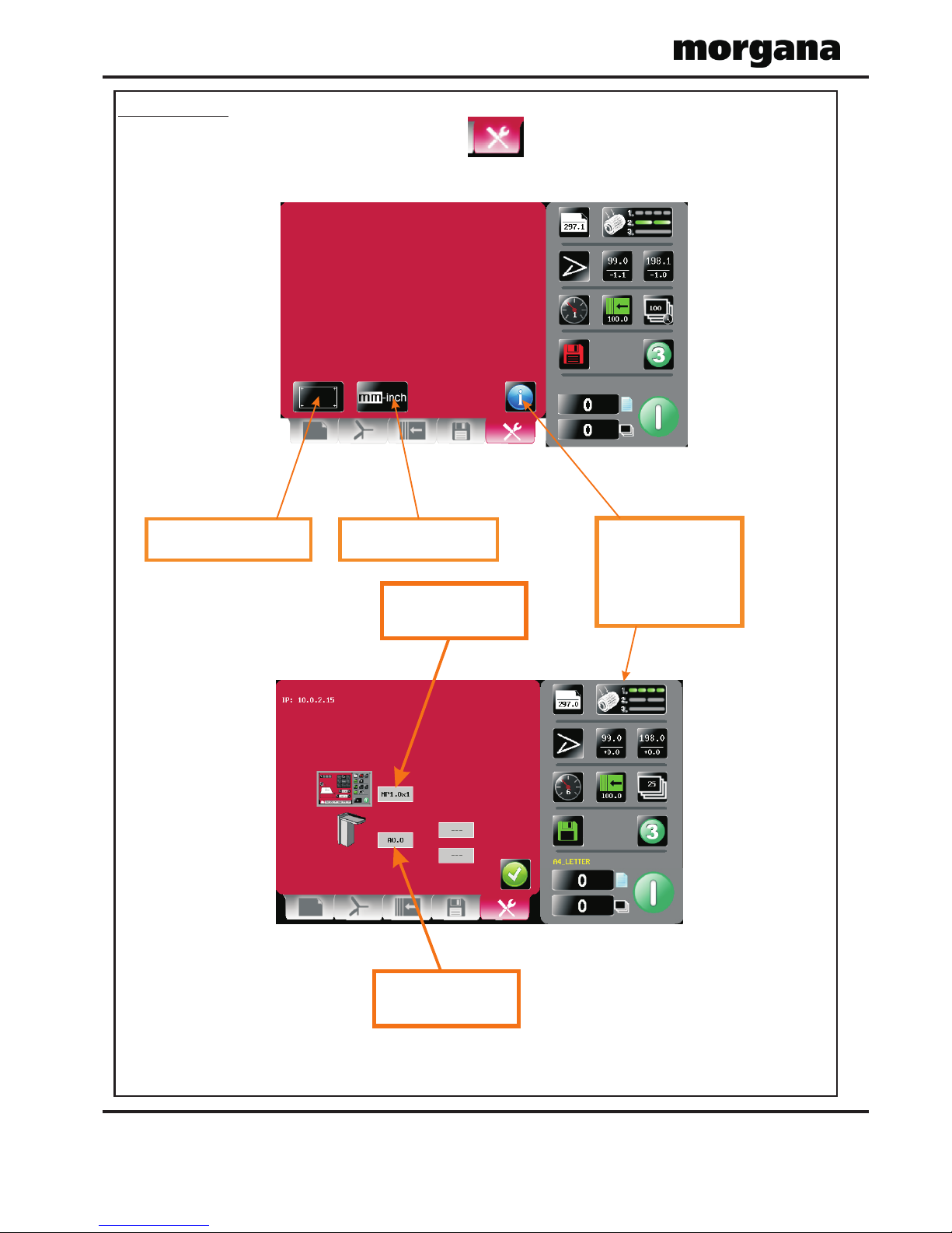
Tools Menu.
To get to the Tools page click the lower tab
Machine main board
software revision
Touch screen software
revision
Operating the DocuFold Pro Operating the DocuFold Pro
Clicking this icon will
show Machine
program revision &
Touch Screen
software revision.
Touch Screen Calibration
Change Machine measurement
settings, Imperial / Metric
See Page 27
Page 27
DocuFold Pro
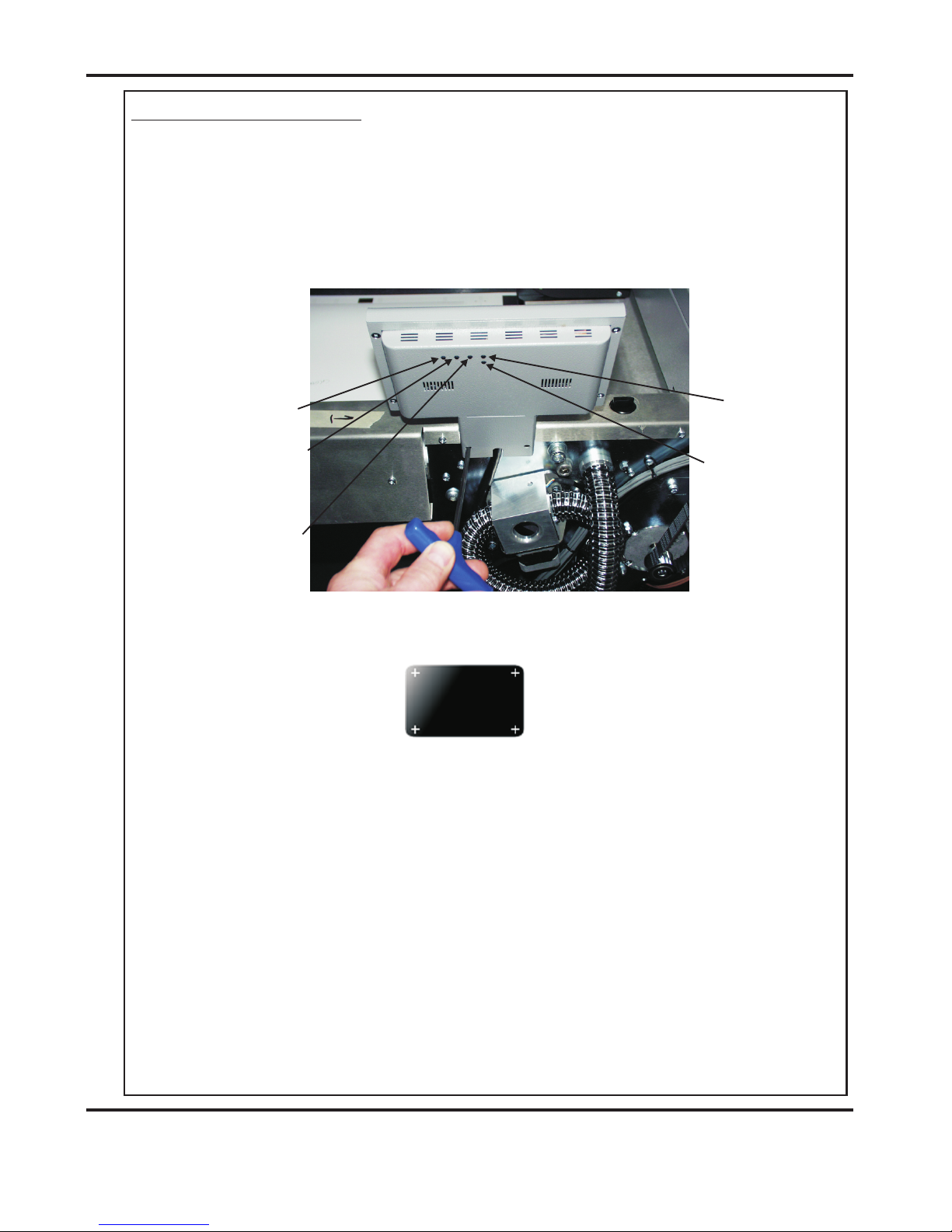
Touch Screen Calibration.
1. Switch the mains power on and wait for the main screen to appear before
commencing to check the horizontal and vertical position of the display.
The position of the display within the surround is achieved by operating the button
at the rear of the housing, press this a number of times to obtain the correct
orientation required, move to the next button to move the position to centralize
horizontal.
2. (i) Select the tools menu tab, and then Select the Touch Screen calibration icon.
(ii) Using a plastic pointer, soft leaded pencil, biro cap etc. and with gentle pressure.
Touch the centre of the cross in each corner of the Touch Screen, as prompted, by
the hand graphics. This procedure will calibrate the Touch Screen.
Brightness
Contrast
Horizontal
Vertical
UP
(Increase value)
DOWN
(Decrease value)
Display
ON/OFF)
AV / Display
Channel

DocuFold Pro
PAPER
Page 28
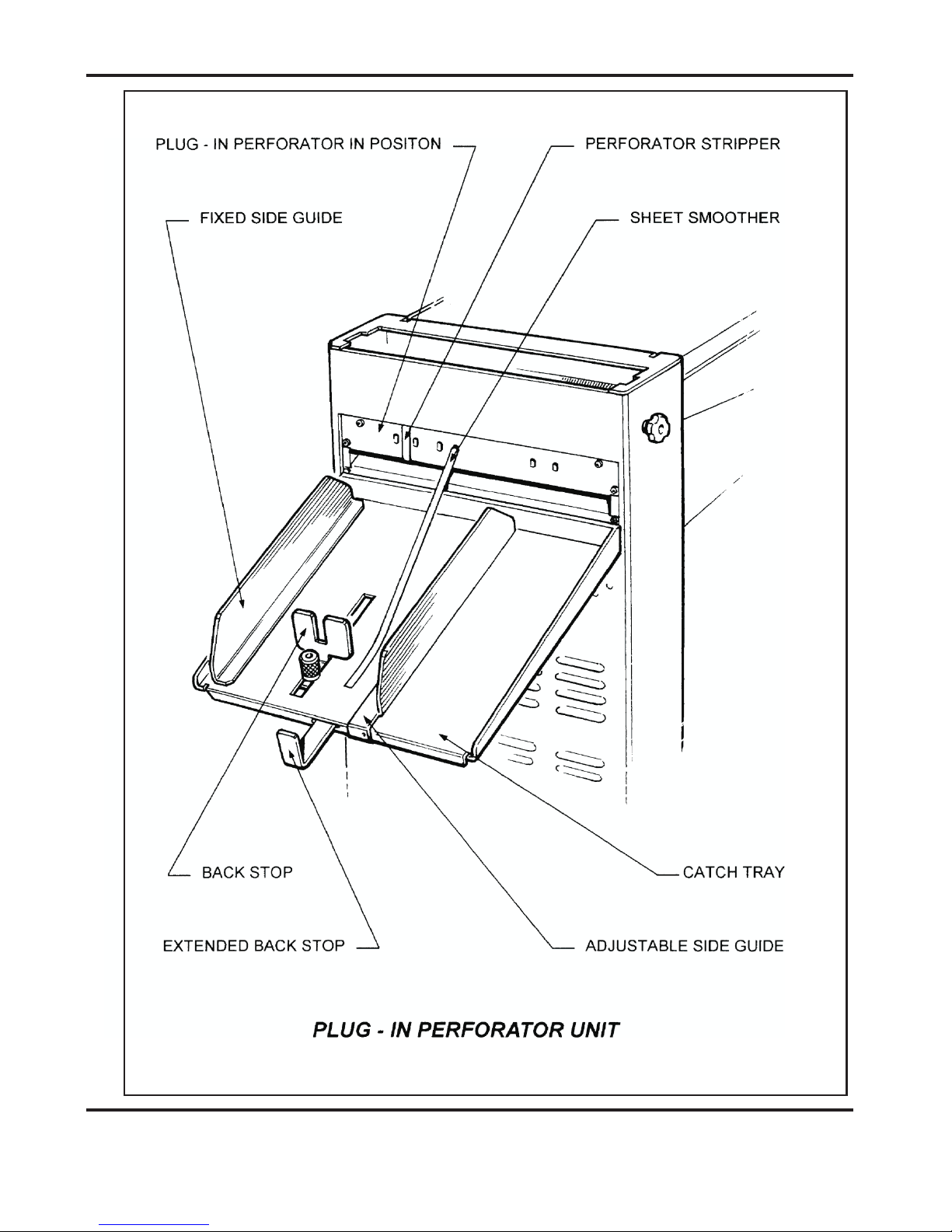
PLUG-IN PERFORATOR
The plug in perforator unit is used for perforating, scoring and when folding card cover
stock; and should be stored on the rear stowage hooks.
ALWAYS UNPLUG POWER CONNECTORS BEFORE REMOVING FOLD PLATES
OR PLUG-IN PERFORATOR.
Remove the top fold plate and fit the catch tray in position by hooking it over the
opening for the top fold plate. The plug in perforator unit then locates the same as the
fold plate and again, take care not to twist when fitting into position. You may need to
turn the hand wheel and push the perforator unit inwards to engage the drive gear. Plug in
the lower fold plate power connector into the perforator unit.
For all applications, the unit is set on the bench, using the scale to indicate the positions of
the blades and hubs. It is important to spread the hubs evenly across the width of the
work to reduce the risk of paper jams.
1. When perforating or scoring without folding, the upper fold plate must be removed
and replaced with the lower fold plate.
Ensure that the tilt roller is at zero, plug the upper plate connector into the lower plate.
To prevent damage to the unused upper plate when scoring or perforating, store safely on
the stowage hooks at the reverse side of the machine.
Press the start button, the built in deflector on the fold plate will close automatically
to the deflect position.
Note: - the Docufold Pro will automatically recognise that the lower plate is in the upper
plate position and that the plug-in perforator unit is in the lower plate position.
Press the start button again to run the job, or the ‘3’ button to run three test sheets.
Note: - Always run perforating or scoring jobs on pulse feed.
FITTING PERFORATER BLADES
The perforator blades are split into two matching halves and are fitted to the upper hubs
as shown in the drawing using the four screws supplied.
Operating the DocuFold Pro Operating the DocuFold Pro
NOTES:-
When perforating or scoring with folding, the upper fold plate remains in position,
at the top.
NOTE:-
2. If any of the fold plates, or the plug in perforator unit are removed from the machine;
the guard circuit is automatically broken, for safety reasons, to prevent the fold
rollers from rotating.
Page 29
DocuFold Pro
FOLDER
DocuFold Pro
PAPER
Page 30
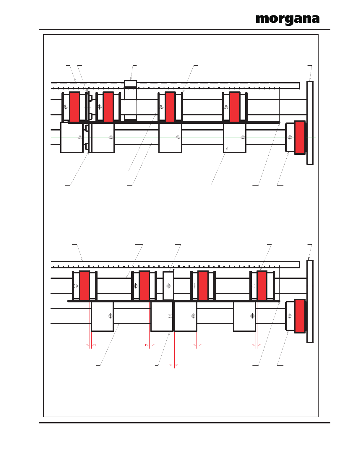
UPPER TYRE AND HUB ASSEMBLIES
LOWER HUBS (SOLID)LOWER PERF SHAFT
FRAME PADUPPER PERF SHAFT
DRIVE HUB
1,0 mm
( 3/64")
EDGE OF SHEET
1,0 mm
( 3/64")
1,0 mm
( 3/64")
RECOMMENDED SCORER SET - UP
SCALE
1,0 mm
( 3/64")
1,0 mm
( 3/64")
SCORER
1522 21 20 19 18 17 16 4 3 2 1 0567891011121314
DRIVE HUB
SCALE
RECOMMENDED PERFORATOR SET - UP
EDGE OF SHEET
FRAME PAD
UPPER PERF SHAFT
LOWER HUBS (SOLID)LOWER PERF SHAFT ANVIL
PERFORATING BLADE PERFORATOR STRIPPER UPPER TYRE AND HUB ASSEMBLIES
22 21 20 19 18 17 16 4 3 2 1
0
567891011121314
Operating the DocuFold Pro Operating the DocuFold Pro

Page 31
DocuFold Pro
FOLDER
SETTING PERFORATORS
Upper and lower hubs can be positioned on the shaft by unscrewing the 2mm-grub screw.
Slide the hub with the blade attached along, the shaft into position to correspond to the
work using the scale as a guide. For example, to perforate 20mm from the edge of an A4
sheet, you would set the blade at 190mm (210 minus 20). When positioned re-tighten the
2mm-grub screw. Important - Do Not Over Tighten This Grub Screw
Slide the hub with the anvil, up to the perforator blade and the remaining upper and lower
hubs, set as the drawing, remembering to spread them to support the sheet fully across its
width.
Clip the perforator stripper adjacent to the upper hub as shown. Plug the unit into
position, fit the sheet smoother into position to hold the sheets down and run the machine
at the slow speed to check position.
Adjust the backstop and side guide to suit the work.
For work longer than the backstop will allow, remove the backstop and use the extended
backstop that is located underneath the catch tray.
There is a full range of perforator blades available as follows:
For fine perforation 56 tooth - Part Number 1.99-41
For Paper 28 tooth - Part Number 1.99-12
For heavier Stock 20 tooth - Part Number 1.99-10
For use with blades Anvil - Part Number 1.99-35
Slitter set for cutting - Part Number 1.99-13
SCORING
It is possible to score work using the plug in perforator. The scorers are split in two
halves, fitted to the upper shaft and set as shown in the drawing using the scale on the
unit as a guide to position. The lower hubs are moved up to but just clear of the scoring
blade. The actual gap is critical and may require some experimentation to obtain a
satisfactory score line. As with perforating, the remaining hubs must be spread to support
the sheet fully across its width.
Scorers available:
Type A
Part Number
6.99-05 for most card
Type B
Part Number
6.99-06 for deep score
Type D
Part Number
6.99-09 for paper

DocuFold Pro
PAPER
Page 32
FOLDING CARD
For best results, the card material should always be printed cross grain as this causes less
resistance when folding. Pre scoring of card stock is also recommended
By using the plug in perforator unit to deliver card, the problem of the stock curling will
be minimised. Put the upper plate into the upper plate position and the plug-in perforator
unit into the lower plate position. Plug in power connectors - upper into upper fold plate
and lower into perforator unit.
Set the backstop and the moving side lay to suit the work. Set the paper length.
Press the start button, the upper plate will automatically move to half the length of the stack
of cover stock.
Fine adjustments may be necessary to the fold position as described on page 16.
It is recommended that when folding card, the machine be set to batch after twenty
sheets, which will allow easy off loading. For longer runs an optional rear delivery belt
stacker (Assy. No. 9-09-01) is recommended to be used.
In the event of a paper jam, the sensor will cut out the main switch. The main fold rollers
are linked to a clutch, which will prevent sheets continuing to feed.
PAPER JAMS
If for some reason a piece of paper jams in the machine, remove and check inside the fold
plates. If there is paper jammed around the fold rollers take hold of a roller and wind
them by hand to remove the jam. If it is impossible to wind the roller by hand, remove
the roller assembly as described below. After clearing a paper jam, always check inside
the fold plate (see Fold Plate Section) to make sure no torn pieces of paper are jammed
inside the plate.
ROLLER ASSEMBLY - REMOVAL
The complete roller assembly unit can be removed from the machine simply by
unscrewing the knobs (Y) on each side and taking hold of the rear roller and lifting out
the unit. This is beneficial to clear paper jams, to clean the roller and for maintenance.
With the roller assembly removed, the safety circuit prevents the machine from running.
Replace the roller unit in the reverse sequence. Clean the rollers with a stiff brush
between the grooves using QD wash supplied by Morgana.
Operating the DocuFold Pro Operating the DocuFold Pro

Page 33
DocuFold Pro
FOLDER
ROLLER ADJUSTMENT
The unique fold roller design of your Morgana Docufold Pro will fold most paper stocks without
the need for adjustment. If you have a requirement to fold very delicate or thicker stock or refeeding to produce a cross-fold the fold roller gap can be easily adjusted as follows: -
1. Remove the roller assembly from the machine as described above.
2. Loosen the Cap Head Screw on the operators side of the roller that you wish to adjust (any
of the 3 outer rollers) using the 5 mm Bondus ‘L’ wrench provided & release the M8 lock
nut on the non-operators side with the 13 A/F spanner provided.
3. Insert the 4 mm hex ball driver into the socket screw at the end of the roller shaft and rotate
in the required direction to adjust the roller gap.
4. The graphics on the inside of the roller side plate show which way to turn the roller to adjust
the gap relative to the centre roller.
5. Re-tighten the half nuts & cap head screws to lock the roller into position.
6. Repeat procedure for each roller that you wish to adjust and then replace the roller assembly
into the machine.
7. Reset the roller tilt knob (R) back to the zero central position and screw in the Clamping
knobs (Y).
Rotate Roller in this direction to increase Gap
(each graduation equals 0.1 mm of gap adjustment)
Section Through Roller Assembly
Rotate Roller in this direction to increase Gap
(each graduation equals 0.1 mm of gap adjustment)
Rotate Roller in this direction to increase Gap
(each graduation equals 0.1 mm of gap adjustment)
Centre Roller (Fixed)
3 Outer Rollers (Adjustable)

DocuFold Pro
PAPER
Page 34
SENSOR CLEANING
The sensors to detect and count the sheets are located on the ends of the ball holder just next to
the fold roller unit. If the counter is failing the sensor can be accessed for cleaning by
removing the roller assembly as described on page 32. Clean by using a soft brush or damp
cloth.
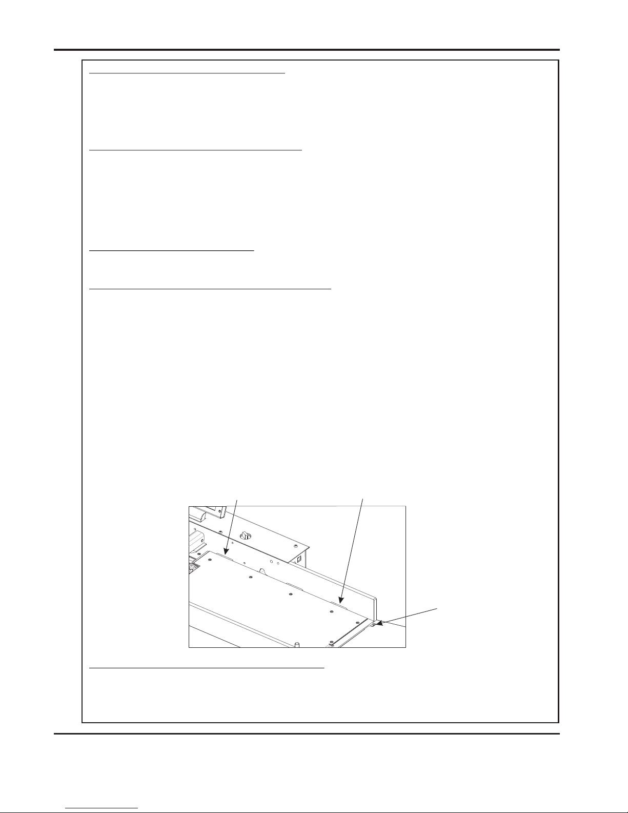
FOLD PLATES - MAINTENANCE
The fold plates can be opened up for maintenance, removing paper jams, cleaning, etc by
removing the two bolts shown below. The fold plate can then be hinged open.
Bolt
Bolt

Page 35
DocuFold Pro
FOLDER
FOLDING TIPS AND TROUBLE SHOOTING:
SHEETS DIFFICULT TO FEED
Check that you have not got too many sheets in the feeder. Heavy-coated stock will not feed as
high a pile as for example 80-gsm copier paper.
Make sure the moving side lay is not pushed in too tightly against the paper. Similarly, if the
moving side lay is set too far away from the paper stack, this will allow the air to escape instead
of blowing through the paper.
Make sure that the gap under the paper gate (B) is not set too low.
Turn the Air separation knob (E) to the high position.
Make sure that air distribution knob (D) is set correctly.
If the paper width varies you may need to trim the sheets to the same size.
If the paper is curling upwards the suction drum may not be able to pull the sheet downward to
wrap around the drum for efficient feeding. You may need to bend the sheets downward prior
to loading.
DOUBLE SHEET FEEDING
Make sure the gap under the paper gate (B) is not set too high.
Make sure the air distribution knob (D) and the air separation knob (E) are at the correct setting.
In extreme cases you may need to separate the sheets prior to loading.
Make sure you run on Pulse not Stream.
FOLD IS NOT SQUARE OR CONSISTENT
Check the sheets are all exactly the same size and are square before folding as you can only fold
accurately if the material is consistent.
Make sure you have no foreign bodies such as fragments of torn paper inside the fold plates or
the fold rollers.
Check that the fold plates are locked and located securely and that the roller tilt mechanism is
set to zero and locked.

DocuFold Pro
PAPER
Page 36
PAPER WILL NOT STACK CONSISTENTLY:
Make sure the feed is consistent before attempting adjustments to the Delivery Roller.
Set the delivery roller position as described in the manual. Sometimes a small repositioning of
the roller will improve the stacking. See Delivery Roller (Page 19)
If the paper is too curly when being delivered, place the catch tray and plug in perforating unit
with blades disengaged into position and deliver out the back. This applies to single fold
applications only. If two folds are required, you may need to reduce the weight of stock to
achieve the desired results.
PAPER WILL NOT DEFLECT WHEN USING ONE FOLD OR PERFORATING:
Check to make sure that the second plate is being used as the deflector.
Make sure that the plate is located securely and that the deflector bar is wound right to the end.
Set the tilt roller mechanism to zero.
Check that the material is not too heavy to deflect.
TOTAL AND BATCH COUNTER NOT WORKING:
Clean the sensors as described in the manual.
OVERLAP ERROR KEEPS APPEARING ON TOUCHSCREEN
If the overlap keeps tripping in and cutting off the machine, first check you are not feeding
doubles and reset the feeder.
Overlap tripping can also mean that the machine is slowing slightly which may mean the
material is too heavy.
Check that you have no foreign bodies or torn paper stuck inside the fold plates or machine.
MACHINE WILL NOT RESET
Your Docufold Pro is a mini computer; you must have a clean consistent power supply. Switch
off at power switch (S), wait 20 seconds and re-power.

Page 37
DocuFold Pro
FOLDER
NO POWER TO MACHINE
If the touchscreen display fails to come on, check that isolator switch (S) is not pressed in.
To release, turn knob clockwise.
Check power supply to the machine.
MAIN SWITCH CUTS OUT:
The feeder will cut out automatically after 100 seconds if the main switch is left on
without the feed switch being activated.
The compressor inside the machine requires up to 28 amps to start running. You must
have the machine plugged directly into a 30-amp ring main. Do not attempt to run the
machine with an extension lead.
The main switch will cut out if you have a paper jam or overlap is indicated.
FOLD ROLLER REPLACEMENT:
Your Morgana Docufold Pro has been designed to make fold roller replacement an easy and
low cost operation. Your local sales agent will be able to supply you with a complete
replacement roller assembly which allows you to change the roller assembly yourself as
described in the roller assembly removal section of this manual. You will need to send
back to your agent the existing roller assembly.

Page 38
DocuFold Pro
Error Screens
Sheet did not arrive.
If the machine stops and error message 01 is displayed on the touch screen, this
indicates that the paper did not arrive at the end of the suck process; so the machine
timed out. Press the green tick button and then press the start button.
Overlap
If the machine stops and error message 13 is displayed on the touch screen, this
indicates that the ‘Lead Edge Sensor’ has seen a sheet subsequent to the first
one as being longer. Again this could actually be a longer sheet, OR it could be a
sensor problem (if it is a recurring problem). Check that the paper gate has been set
correctly.
Upper fold plate set out of range.
If the touchscreen shows the error screen shown below, this indicates that the fold
that has been set for the upper fold plate is out of range.
Page 39
DocuFold Pro
Error Screens (continued)
Lower fold plate set out of range.
If the touchscreen shows the error screen shown below, this indicates that the fold
that has been set for the lower fold plate is out of range.
Incorrect fold plate fitted for perforating or scoring (without folding).
If the touchscreen shows the error screen shown below, this indicates that the wrong
fold plate is fitted. When perforating or scoring (without folding) the short fold plate
must be fitted in the upper slot position.
Incorrect fold plate fitted for perforating or scoring (with folding).
If the touchscreen shows the error screen shown below, this indicates that the wrong
fold plate is fitted. When perforating or scoring (with folding) the long fold plate
must be fitted in the upper slot position.

DocuFold Pro
PAPER
Page 40
WARNING......
THE BLADES FOR ANVIL, PERFORATING, & SCORING SETS ARE
SUPPLIED AS MATCHED PAIRS AND SHOULD NEVER BE MIXED -UP OR
LEFT UN-PROTECTED AS SERIOUS DAMAGE WILL RESULT.
Error Screens (continued)
Perforating / Scoring unit not fitted.
If the touchscreen shows the error screen shown below, this indicates that the
machine has been set for perforating or scoring (with or without folding) and the
perforating / scoring unit has not been fitted.
System switch not on.
If the touchscreen shows the error screen shown below, this indicates that the system
switch must be switched to the ON position.
Lead Edge Sensor Fault
If the machine stops and error message 60 is displayed on the touch screen, this
indicates that the lead edge sensor is blocked. Check that the paper path is clear.
This error message could also mean that the lead edge sensors are faulty or need
cleaning.
Page 41
DocuFold Pro
FOLDER
DISPATCH KIT
90 - 134
DOCUFOLD PRO OPERATORS MANUAL
90 - 018
ROLLER CLEANING KIT
62 0 - 006
ALLEN KEY
- 3mm
62 0 - 007
HEX BALL DRIVER
-
2mm
62 0 - 004
HEX BALL DRIVER
- 4.0mm
62 0 - 025
BONDUS 'L' WRENCH
-
2.5mm
1 - 99 - 41
PERFORATING SET
-
56T
- SLITTING
65 0 -04 0
POWER CORD
- C19 - 3Pin - UK
WARNING......
THE BLADES FOR ANVIL, PERFORATING, & SCORING SETS ARE
SUPPLIED AS MATCHED PAIRS AND SHOULD NEVER BE MIXED -UP OR
LEFT UN-PROTECTED AS SERIOUS DAMAGE WILL RESULT.
ITEM PART NUMBER QTY DESCRIPTION
1
1
2 1
3
4
1
5
8
9
10
1
11
1
1
14
1
6
7
1
1
15
1
1
5
1
62 0 - 020
HEX BALL DRIVER
-
2.5mm
1
62 0 - 027
BONDUS 'L' WRENCH
-
5.0mm
1
62 0 - 032
COMBINATION SPANNER
- 13 A/F
62 4 - 018
DISPATCH BOX
1 - 99 - 3 5
6 - 99 - 05
ANVIL SET
SCORING SET
- TYPE A
9-95-13 (USA)
65 0 -04 1
POWER CORD
-
C19 - 3Pin - USA
1
13
12
61 7 - 004
GLASS BALL
16
65 0 -01 6
L6 - 15P Re-Wirable Plug (Used on USA Only)
1
9-95-12 (UK)
2
71 - 083 -01
OUTRIGGER FOOT
17
2
40 1 -02 -05 0- 008
SCREW - PAN POZI TAPTITE - M5 X 8 LONG
18

DocuFold Pro
PAPER
Page 42
ACCESSORIES....
....May be obtained from your
dealer and fitted to your machine using
the instructions supplied, or by
consulting your operators manual.
OPTIONS....
....May also be obtained and fitted
by your dealer. You should not attempt
to fit options yourself as specialist tools
and knowledge are required.
ACCESSORIES & OPTIONS
ITEM PART NUMBER DESCRIPTION
6-99-06 SCORING SET - TYPE B1
6-99-09 SCORING SET - TYPE D2
1-99-10 PERFORATING SET - 20T SLITTING3
1-99-11 PERFORATING SET - 20T SLITTING - HEAVY DUTY
4
1-99-12 PERFORATING SET - 28T SLITTING
5
1-99-41 PERFORATING SET - 56T SLITTING6
1-99-13 SLITTING BLADE SET
7
1-99-35 ANVIL SET8
98-018-02 PERFORATOR STRIPPER SET - LONG
9
69-033 SHEET SMOOTHER - STACKER - LONG10
6-99-36 PAPER PROFILE ROLLERS - SET (SPLIT)11
Technician Maintenance
It is recommended that your machine is fully serviced at least once every six months
by a factory trained Service Engineer.
Page 43
DocuFold Pro
FOLDER
75 - 06 - 02
TOUCH SCREEN ASSY - 7" (NEW CONTROLLER)
92 - 027-01
DRIVE BELT - Delivery - Flat 12mm
93 - 022
DRIVE BELT - Vacuum Roller
95 - 151 - 01
HOSE - Vacuum
95 - 153 - 01
HOSE - Valve
95 - 189
DC MOTOR PCB ASSY.
76 - 272
PSU ASSEMBLY - ATX12V - 300W
96 - 028 - 02
FOLD ROLLER ASSEMBLY - Standard
96 - 049 - 02
FOLD ROLLER ASSEMBLY - Bottom
601 - 021
MAGNETIC ACTUATOR
90 - 08 - 01
PCB - FOLD PLATE MOTOR DRIVE
97 - 076
STEPPER MOTOR & LEAD ASSEMBLY
PART NUMBER DESCRIPTION
75 - 500 - 08
MINI ITX MOTHERBOARD - DOCUFOLD PRO
92 - 010
TRANSPORT BELT
Delivery
93 - 021
FEED BELT
93 - 028
SMOOTHER - Delivery
95 - 150 - 01
HOSE - Exhaust
95 - 152 - 01
HOSE - Sheet Separation
95 - 187
POT & LEAD ASSEMBLY - DELIVERY ROLLER
96 - 031
DRIVE BELT - Large Roller Drive
97 - 121
POT & LEAD ASSEMBLY - FOLD PLATE
174 - 19 - 01
RS232 ADAPTOR PCB ASSY
RECOMMENDED SPARES
94-088
UPPER SENSOR ASSEMBLY
93 - 042
LOWER SENSOR ASSEMBLY
601 - 111
TAPERED FERRULE - SR1520 - Ø7.9 x Ø13 x 23 LG.
607 - 027
TIMING BELT
609 - 011
'O' RING
609 - 013
'O' RING
607 025
TIMING BELT
606 - 030
SCALLOP KNOB - Black
607 - 022
TWIN GRIP TIMING BELT
607 - 026
TIMING BELT
607 - 160
TIMING BELT - T2.5 /317.5 x 6MM WIDE
609 - 012
‘O’ RING - WHITE SILICON - Ø50 X Ø4
90 - 06 - 02
CONTROL PCB ASSY + CHIP-DOCUFOLD PRO-UL
75- 530-01
TRANSFORMER ASSEMBLY - 230V TO 110V

Page 44
DocuFold Pro
NOTE.....
The items listed above represent parts which are subject to wear, loss, or
accidental damage, and is included for your guidance only.
Replacement of most of the parts fitted to your machine requires specialist
knowledge and should therefore be entrusted to your dealer.
RECOMMENDED SPARES
609 - 014
'O' RING
PART NUMBER DESCRIPTION
613 - 255
SOLENOID COIL
655 - 016
POWER SUPPLY UNIT - SWITCHED MODE - 48V
609 - 023
‘O' RING
652 - 011
SWITCH - LOW CURRENT COIL - BLACK ROCKER
613 - 365
EMERGENCY STOP SWITCH
613 - 137
PLUNGER & SPRING ASSY
655 - 015
POWER SUPPLY UNIT - SWITCHED MODE - 24V
613-023
FUSE 3.15A - Fast Blow
FUSE 15A - Anti-surge
652-047
FUSE 4A - Anti-surge
681-015
FUSE 500mA - Anti-surge
681-020

Page 45
DocuFold Pro
FUSE POSITIONS & RATINGS
(POSITION ET CLASSIFICATION DES FUSIBLES)
T500mAH 250V (681-020)
PSUs (24V & 48V)
T4.0AH 250V (681-015)
(FUSIBLE PSUs (24 V & 48 V)
TRANSFORMER ASSY.
T15AH 250V (652-047)
MAINS IN
F3.15AH 250V (613-023)
DC MOTOR BOARD

Page 46
PRODUCT RECYCLING & DISPOSAL
Application of this symbol on your equipment is confirmation that you
must dispose of this equipment in compliance with agreed national
Procedures.
In accordance with European legislation end of life electrical and
electronic equipment subject to disposal must be managed within
agreed procedures.
Prior to disposal please contact your local dealer or representative for
end of life take back information.
European Union
Disposal Information for Commercial Users
Disposal Information for Domestic Users
Application of this symbol on your equipm e n t is confirm ation that
you sh o u ld not dispose of the equipment in the norm al household
waste stream .
In accordan ce with European le gislation, end of life electrical and
electronic equipm ent subject to disposal must be segregated
from household waste.
Private households with in EU Member States may return used
electrical and electronic equipment to design a ted collection
facilities free of charge. P lease contact your local disposal
authority for info rmation.
In som e Member States when yo u purchase new equipment your
local reta iler may be required to take back your old equipment
free of charge. Please ask your retailer for inform ation.
Other Countries
Please contact your local waste authorities and request disposal information.
DocuFold Pro

Page 47
DocuFold Pro
Mod No.Rev. Mod Description Date Mod By
REVISION HISTORY
3 ECO2811 23/01/13 BAL
Page 45 Changes:- T15A Fuse was F15A.
 Loading...