

Morgana BM350, BM500 Operating Instructions Manual
Read this manual carefully before you use this product and keep it handy for future
reference.
For safety, please follow the instructions in this manual.
Operating Instruction
Doc no: T10200G
Date: 27 June 2017
BM350/BM500
Booklet Maker System

WARNING:
This is a Class A product.
In a domestic environment this product may cause radio interference,
in which case the user may be required to take adequate measures.
The product (System) which is connected to this machine will be class A.
NOTE:
The domestic environment is an environment where the use of broadcast radio and
television receivers may be expected within a distance of 10m of the apparatus concerned.

Introduction
This manual contains instructions on the operation and maintenance of this machine.
To get maximum versatility from this machine all operators should carefully read and follow the
instructions in this manual. Keep this manual in a handy place near the machine.
Please read the Safety Information before using this machine.
It contains information related to USER SAFETY and PREVENTING EQUIPMENT PROBLEMS.
How to read this manual
Notation conventions
Whenever necessary, the following points for attention are indicated in this manual.
WARNING:
Indicates a potentially hazardous situation which, if instructions are not followed,
could result in death or serious injury.
CAUTION:
Indicates a potentiality hazardous situation which, if instructions are not followed,
may result in minor or moderate injury or damage to machine or property.
NOTE:
This sign refers to:
Remarks for making the operation much easier.
You get practical hints or knowledge to assist you in the machine operation such as:
• Preparations required before operating
• How to prevent papers from being misfed or damaged
• Precautions required or actions to take after misoperation
• Limitations like numerical limits, functions that cannot be used together or conditions,
under which a particular function cannot be used or obtained.
Information.
[ ]
Keys that appear on the machine’s display panel.

WARNING:
• To avoid hazardous situations e.g. electric shock or danger while exposed to moving,
rotating or cutting devices, do not remove any covers, guards or screws other than
those specied in this manual.
• Turn off the power and disconnect the power plug (by pulling the plug, not the cable)
if any of the following conditions exists:
• You drop objects or spill something into the equipment.
• You suspect that your equipment needs service or repair.
• Your equipment’s covers has been damaged.
• You notice unusual noises or odours when operating the equipment.
• If the power cable or plug becomes worn out or otherwise damaged.
• Before cleaning and care (unless otherwise specically instructed).
• Electromagnetic compliance:
• This is a Class A product. In a domestic environment this product may cause radio
interference in which case the user may be required to take adequate measures.
• The product (System) which is connected to this machine will be class A.
Safety Information
When using this machine, following safety precautions should always be followed.
Safety during operation
General safety
WARNING:
• Always connect the equipment to a properly grounded power source (wall outlet).
If in doubt, have the power source checked by a qualied electrician.
• Improper grounding of the equipment can result in electrical shock. Never connect the
machine to a power source that lacks a ground connection terminal. This machine is
designed for specic purpose only. Any use going beyond this specic purpose is regarded as beyond the determination. The manufacturer will not be liable for damages
resulting from any use beyond the determination, unallowed operation, respectively.
The user alone bears the risk.
• Do not make arbitrary changes or modications to the machine. The manufacturer will
not be liable for modications made at the machine on your own and damages resulting thereof. EC declaration of conformity and the mark CE will be invalidated, if you
make changes at the machine or at the individual components.
• Do not override or bypass electrical or mechanical interlock devices.
• The machine is to be used only by authorized and instructed persons.
The responsibilities on operating the machine have to be strictly laid down and observed so that there are no unclear competences regarding safety aspects.
• Vent holes serve for air circulation to protect the machine from overheating.
Make sure that the holes are not covered.
• Do not expose ngers or other parts of the body to moving, rotating or cutting devices
such as for instance between upper and lower trimmer knives.
• Always locate the equipment on a solid support surface with adequate strength tor the
weight of the machine.

CAUTION:
• The machine and its peripherels must be installed and maintained by a customer service
representative who has completed the training course on those models.
• Always follow all warnings marked on, or supplied with, the equipment.
• When you disconnect the power plug from the wall outlet, always pull the plug (not the cable).
• Disconnect the power cord before you move the machine. While moving the machine, always
exercise care and make sure that the power cord will not be damaged under the machine.
• Always contact service if relocating the equipment.
• Do not move the machine while the machine is running.
Do not open covers while the machine is running.
Do not switch off the power while the machine is running.
Make sure the machine cycle has ended.
• Lay the power cord in a way that nobody will stumble over it. Do not place things on the cord.
• Never attempt any maintenance function that is not described in this documentation.
• Always keep magnets and all devices with strong magnetic elds away from the machine.
• If the place of installation is air-conditioned or heated, do not place the machine where it will be:
Subject to sudden temperature changes.
Directly exposed to cool air from an air-conditioner.
Directly exposed to heat from a heater.
• If the machine is not used over an extended period of time,
it should be unplugged to prevent damage in the case of overload.
Note:
• The indications like front and rear, left and right refer to the paper transport direction.
• The operator manual always has to be available at the place of use of the machine.
• In the interest of technical development the company reserves the right to make alterations
to specications without prior notice!

PAGE INTENTIONALLY BLANK.

TABLE OF CONTENTS
What You Can Do With This Machine ............................................................................. 11
Guide To Components ..................................................................................................... 13
Booklet Maker ............................................................................................................................. 13
User interface ............................................................................................................................. 16
Control panel ..................................................................................................................... 16
Options .............................................................................................................................. 18
BM350/500 Booklet Maker ......................................................................................................... 18
Live logo ............................................................................................................................ 18
SQF500 Square Fold Module ..................................................................................................... 19
FTR500 Trimmer Module ............................................................................................................ 21
CST500 Crease Trim Module ..................................................................................................... 23
CR500 Creaser Module .............................................................................................................. 29
BST4000-1 Belt Stacker Module ................................................................................................ 31
BST4000-1 Principle of Operation ..................................................................................... 32
Air Assist Feeder AF602 ............................................................................................................. 33
Vacuum Feeder VF602 ............................................................................................................... 34
1. Basics
Turning On / Off Main Power ........................................................................................... 35
Locating power switches ............................................................................................................. 35
Loading Feeder AF602/VF602 ......................................................................................... 37
Change staple cartridges and Check stapler................................................................. 38
Change left/right staple cartridge(s) ............................................................................................ 38
Check left/right stapler ................................................................................................................ 39
Emptying the trim bin ....................................................................................................... 40
Undocking the Booklet Maker ......................................................................................... 40
Belt Stacker ....................................................................................................................... 41
Setting up Belt Stacker for right-angled mode ............................................................................ 41
Setting up Belt Stacker for Straight Mode ................................................................................... 42
Job Preparation ................................................................................................................ 43
2. Making Booklets
Changing settings ............................................................................................................ 47
General procedure ...................................................................................................................... 47
Paper Size .................................................................................................................................. 47
Selecting standard paper sizes ......................................................................................... 47
Custom sheet size ............................................................................................................. 48
Staple .......................................................................................................................................... 48
Selecting stapling On or Off ............................................................................................... 48

Staple position ............................................................................................................................ 49
Adjusting staple position .................................................................................................... 49
Fold position ............................................................................................................................... 49
Adjusting fold position ........................................................................................................ 49
Fine tuning booklet appearance ................................................................................................. 50
Face Trimming ............................................................................................................................ 51
Select Face Trimming Auto or Manual .............................................................................. 51
Square Fold Module ................................................................................................................... 52
General .............................................................................................................................. 52
Selecting square folding mode .......................................................................................... 53
Square Fold stop gate offset ............................................................................................. 53
Crease Trim Module (Option) ..................................................................................................... 54
Crease - Selecting Crease Mode ...................................................................................... 54
Bleed Trim Settings - General ........................................................................................... 55
Bleed Trimmer - Asymmetric Side Trim ............................................................................. 55
Setting up a feeder job in AF602/VF602 ..................................................................................... 56
AF602 Advanced Settings .......................................................................................................... 57
Operation with AF602 ................................................................................................................. 59
VF602 Advanced Settings .......................................................................................................... 60
Operation with VF602 ................................................................................................................. 65
Hand-feeding ..................................................................................................................... 66
Hand feed mode ......................................................................................................................... 66
Hand feed mode using the tray ................................................................................................... 67
3. Tools
The Tools screen ......................................................................................................................... 69
Stacker full detection .................................................................................................................. 69
Units ............................................................................................................................................ 69
Software version ......................................................................................................................... 70
Square Fold stop gate offset ....................................................................................................... 70
4. Jobs
Handling jobs .................................................................................................................... 71
Saving a Job ............................................................................................................................... 71
Opening and handling stored Jobs ............................................................................................. 72
5. Clearing Misfeed(s)
Clearing misfeed(s) .......................................................................................................... 73
General ....................................................................................................................................... 73
CST module ....................................................................................................................... 74
Clearing misfeed(s) in the paper path ......................................................................................... 74
Infeed “A” area and exit “D” area ....................................................................................... 74
CST, registration and creaser area .................................................................................... 75

Booklet Maker ................................................................................................................... 76
Clearing misfeed(s) ..................................................................................................................... 76
Inside the Booklet Maker ................................................................................................... 76
Clearing misfeed in folder area .......................................................................................... 77
AF602/VF602 Feeder module........................................................................................... 78
Clearing misfeeds ....................................................................................................................... 78
Misfeed/Jam in feeder bin ................................................................................................. 78
Misfeed/Jam in paper transport area ................................................................................. 78
Square Fold Module ......................................................................................................... 79
Clearing misfeed(s) ..................................................................................................................... 79
Inside the Square Fold Module .......................................................................................... 79
Trimmer module................................................................................................................80
Clearing misfeed(s) ..................................................................................................................... 80
Clearing misfeed in input area ........................................................................................... 80
Clearing misfeed in exit area ............................................................................................. 81
Belt stacker ....................................................................................................................... 82
Clearing misfeed(s) ..................................................................................................................... 82
Clearing misfeed on belt stacker ....................................................................................... 82
6. Troubleshooting
Fault codes........................................................................................................................ 83
General ....................................................................................................................................... 83
General fault codes ..................................................................................................................... 85
Clear Misfeed(s) ................................................................................................................ 85
Close cover(s) ................................................................................................................... 86
Empty stacker! ................................................................................................................... 86
CST fault codes .......................................................................................................................... 87
Waste bin full ..................................................................................................................... 87
Booklet maker fault codes .......................................................................................................... 87
Check stapler or Change staple cartridge ......................................................................... 87
Set too thick, remove set ................................................................................................... 87
Remove purged set ........................................................................................................... 87
AF602/VF602 fault codes ........................................................................................................... 88
Jam recovery manual setting VF602 .......................................................................................... 90
Miss error ........................................................................................................................... 90
Jam, Too long, Too thick errors .......................................................................................... 91
Trimmer fault codes .................................................................................................................... 92
Empty trim bin .................................................................................................................... 92
Close trimmer belts ............................................................................................................ 92
Square Fold fault codes .............................................................................................................. 92
Feed errors ........................................................................................................................ 92
Sensor Calibration............................................................................................................ 93
AF602 Sensor Calibration ........................................................................................................... 93
VF602 Sensor Calibration ........................................................................................................... 95

7. REMARKS
Do’s And Don’ts ................................................................................................................ 97
Where to put Your Machine ............................................................................................. 98
Machine environment ................................................................................................................. 98
Power connection ....................................................................................................................... 98
Access to machine ...................................................................................................................... 99
Maintaining Your Machines ........................................................................................... 100
Square Fold module maintenance ............................................................................................ 101
Cleaning feed belts .......................................................................................................... 101
CST Module maintenance ........................................................................................................ 102
Cleaning the paper path transportation nip rollers (12x) ................................................. 102
Cleaning the xing rollers (3x) ......................................................................................... 103
Cleaning the registration cross roller (4x) & friction tires (4x) .......................................... 104
Cleaning the rotator rollers (2x) ....................................................................................... 105
Cleaning the paper path sensors (5x) ............................................................................. 105
Cleaning of creaser tools (2x) .......................................................................................... 107
Adjustment of Bleed Trimmer registration angle (parallell cut) ........................................ 108
Adjustment of Creaser registration angle ........................................................................ 109
AF602 Feeder Maintenance ..................................................................................................... 110
Cleaning AF602 ............................................................................................................... 110
VF602 Feeder Maintenance ..................................................................................................... 112
Cleaning VF602 ............................................................................................................... 112
Limitations in the BM350/BM500 system ..................................................................... 114
Best practice for the BM350/BM500 system ................................................................ 116
8. Specication
Machine Specications .................................................................................................. 117
BM350/BM500 Booklet Maker .................................................................................................. 117
Performance diagrams ............................................................................................................. 118
Square Fold Module ................................................................................................................ 118
FTR Trimmer Module ................................................................................................................ 119
CST Crease Trim Module (option) ............................................................................................ 120
Creaser CR500 (option) ............................................................................................................ 121
Air Feeder AF602 / Vacuum Feeder VF602 (options) ............................................................... 122
BST4000-1 Belt Stacker Module .............................................................................................. 122
System Set Size Guide ............................................................................................................. 123
11
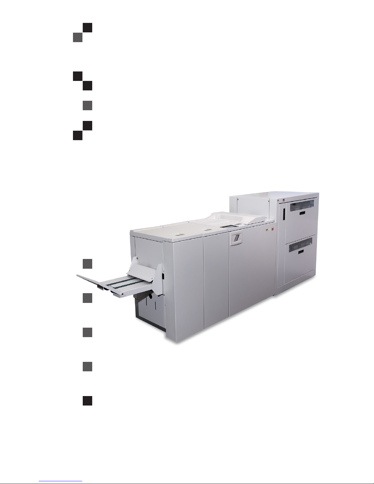
What You Can Do With This Machine
Booklet maker system BM350 / BM500 consists of:
AF602 Feeder Module (optional), a two station high capacity feeder
VF602 Feeder Module (optional), a two station high capacity vacuum assisted feeder
ACF510 Tower Feeder/Collator (optional), a ten station feeder/collator
CST Crease Trim Module (optional), also referred to as the CST Module or the CST
BM350 or BM500 Booklet Maker, a 35 or 50 sheet booklet maker
SQF500 Square Fold Module (optional)
FTR500 Face Trim Module (optional), also referred to as the Trimmer Module or the Trimmer
BST4000-1 Belt Stacker Module (optional), also referred to as the BST Module or the BST
Together they form a system that allows full bleed booklet making. The BM500 upgrade kit raises
the capacity from 35 sheets to 50 sheets. That means that instead of 140 page booklets, 200 page
booklets are possible. The BM500 upgrade kit also includes the Live Logo feature, allowing the
operator to monitor the system status from a distance.
The fed sheets rst enter the CST Module. In order to avoid colour prints to break or dissolve at the
spine when folded, the CST can crease the cover sheet. The CST can also trim the long sides of
the sheets to shape the print-outs to the desired format. To enable full bleed booklets, an FTR Trim
Module have to be installed after the Booklet Maker, se below.
From the CST the print-outs are transported into the BM500 or BM350 Booklet Maker where they
are compiled in the stapler area.
The Booklet Maker jogs and staples the set. The set is then transported further inside the Booklet
Maker to the folding area where the set is folded into a booklet and fed out to the belt stacker or
device attached after the Booklet Maker.
BM350 Booklet Maker
FTR500 Trim Module
(option)
BM500 upgrade kit (option)
incl. Live Logo
SQF500 Square Fold Module
(option)
Belt Stacker
AF602-500 Feeder Module (option)
VF602-500 Feeder Module (option)
continued on next page

12
When a larger number of sheets are folded, an effect called creeping occurs.
In order to rectify creep, a Trimmer Module can be attached after the Booklet Maker.
If so, the booklets are transported from the Booklet Maker into the Trimmer where the trail edge
will be cut off. The Trimmer combined with an CST Module in front of the Booklet Maker enables
the possibility to create full bleed booklets.
After the Booklet Maker, but before the Trimmer, a Square Fold Module can be attached.
The printouts, which have been stapled and folded, will then be fed into the Square Fold Module
where the spine of the booklets will be attened square.
The booklets will have the look of a perfect bound book.
Finally, the booklets are fed out to the Belt Stacker or to a Trimmer.
To allow longer, unattended runs there is an optional high capacity belt stacker avilalable.
The BST4000-1 Belt Stacker Module will stack up to 1000 A4 or 8.5 × 11” booklets of 4 pages.
The Booklet Maker System can also be used for hand-feeding. If no feeder (e.g. AF602/VF602 or
ACF510) is installed, then the Hand Feed Tray shall be used. Even when a feeder is installed it is
still possible to hand feed through the Secondary Hand Feed inlet.
continued from previous page
The user interface/control panel is of
touch screen type. Point at the screen
and press the button or function you wish
to make changes to.
In this sample screen shot, the Staple
button is pressed.
A sub screen is showed.
Make your changes and conrm by
pressing the green check mark or exit
whithout making any changes by pressing the red X. Pressing the house symbol takes you back to the main or home
screen.
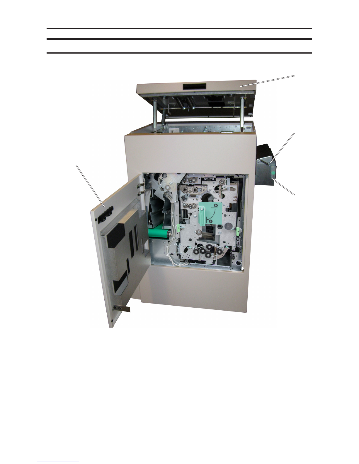
13
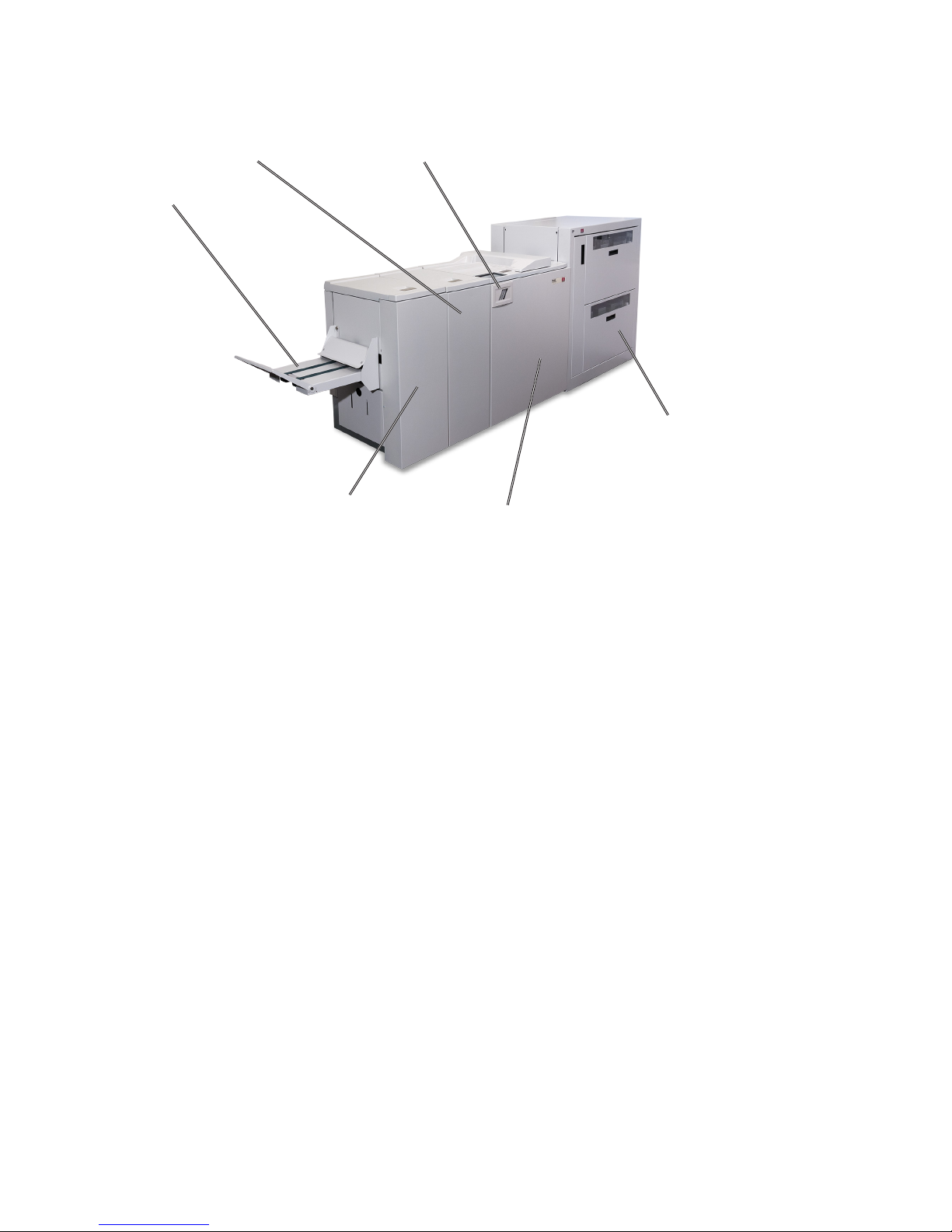
Guide To Components
Booklet Maker
4
8
1
1. Top cover
2. Cover for Secondary Hand Feed
3. Latch handle
4. Live logo, only on BM500 (optional)
5. Belt Stacker
6. Belt Stacker Cover
7. Slot for optional Cover Feeder
8. Hand Feed Tray
2
3
6
7
5

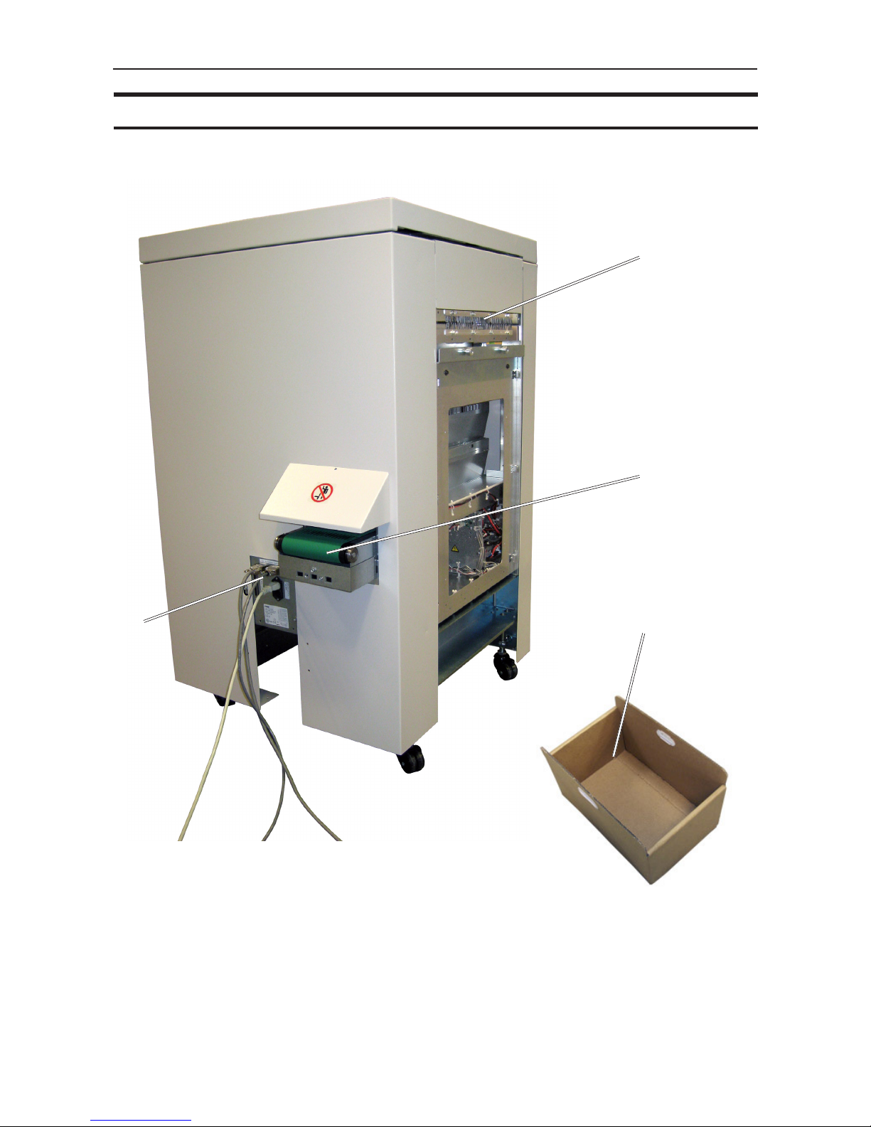
14
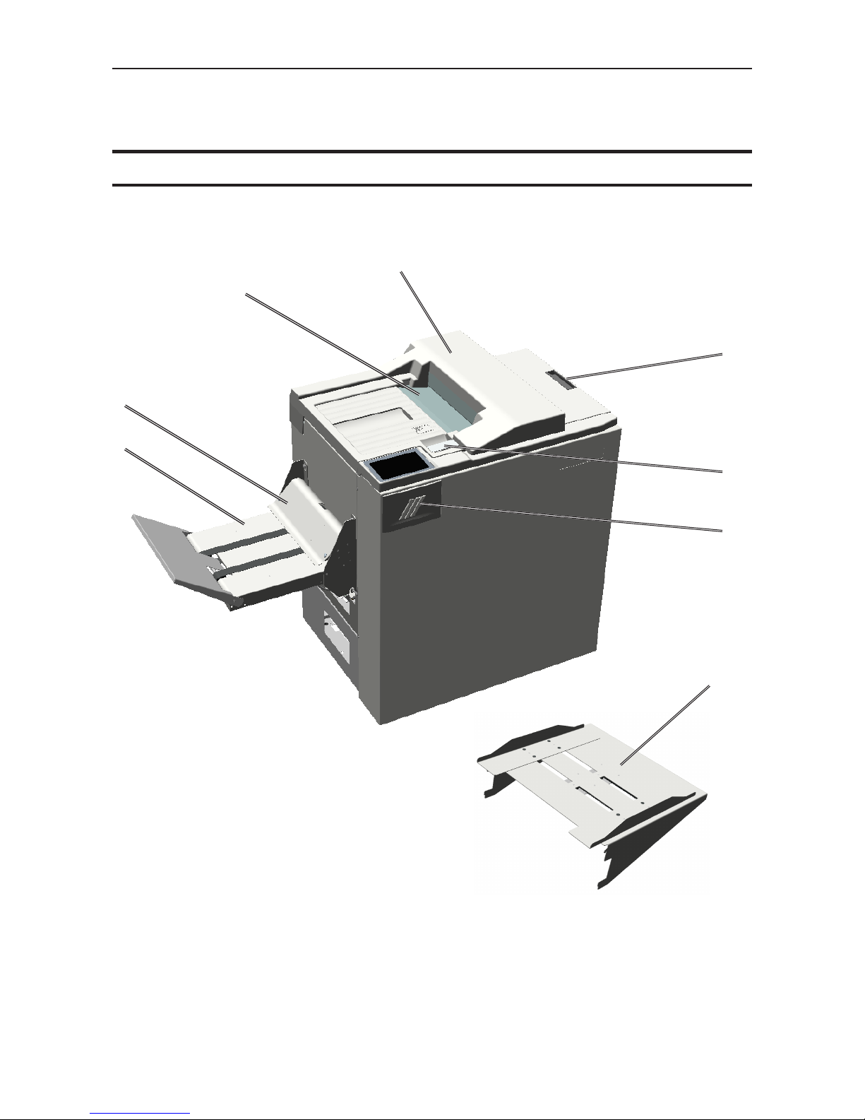
Booklet Maker, continued
1
5
2 3
4
NOTE:
How to connect cables, plugs and jumpers is described at the end of this manual.
1. Belt Stacker Connector
2. Upstreams Communication
3. Downstreams Communication
4. Power Connection
5. Hand feeding paper guides
15
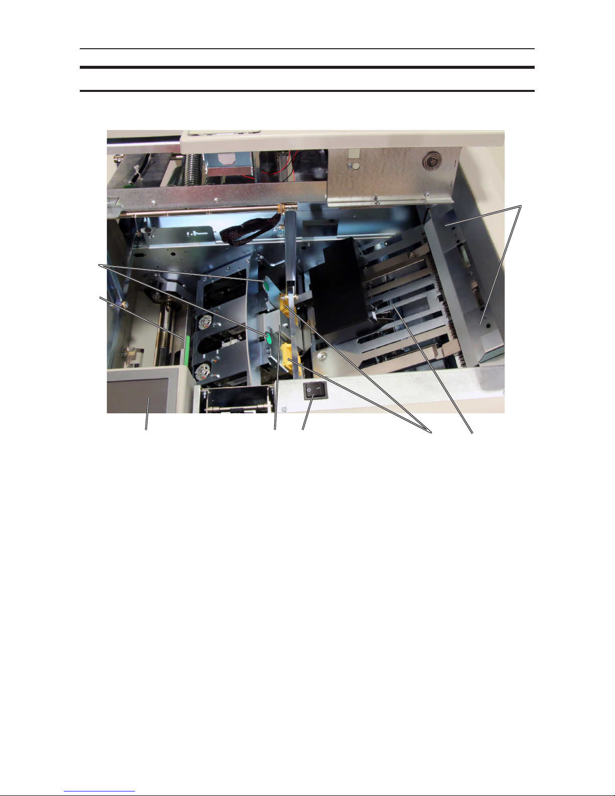
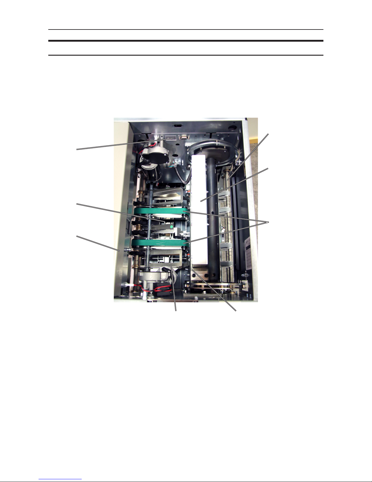
Booklet Maker, continued
1
23456
7
8
1. Hand feeding paper guides
2. Compiler area
3. Staple cartridges (incl. stapler heads)
4. Main power switch
5. Set thickness sensor
6. Control panel
7. Fold roller guide
8. Staple cartridge ejection lever
16
User interface
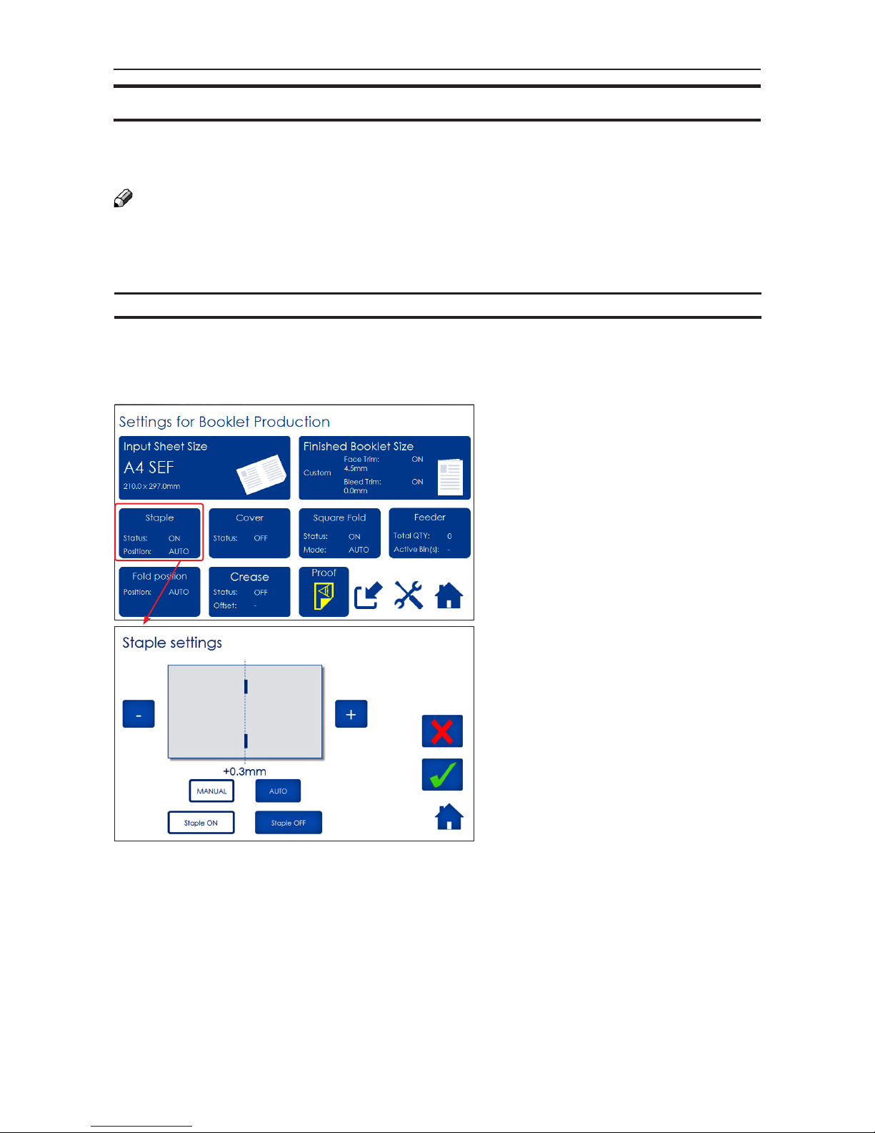
Settings for Booklet Production
Pressing the [Booklet Production] button
in the Start Screen opens the Settings
for Booklet Production screen. From
here you can reach all detailed settings
for setting up the job.
Detailed Settings
Pressing, for example, the [Staple] button in the Settings for Booklet Production screen opens the Staple settings
screen. Here you can perform detailed
settings concerning stapling. Explore
this and other settings more thoroughly
in section 2. Making Booklets.
The control panel is of touch screen type. Point at the screen and press the “button” to reach the
desired function or change the desired setting.
The BM350/BM500 system is controlled from a panel located on the Booklet Maker.
The control panel will allow you to easily set up, adjust and operate the complete system.
An optional “Live logo” makes state of system visible from a distance.
NOTE:
Depending on modules and features installed, the screen may look different from what you see here.
Some functions are greyed out or not visible at all. This manual shows a fully congurated system.
Control panel
17
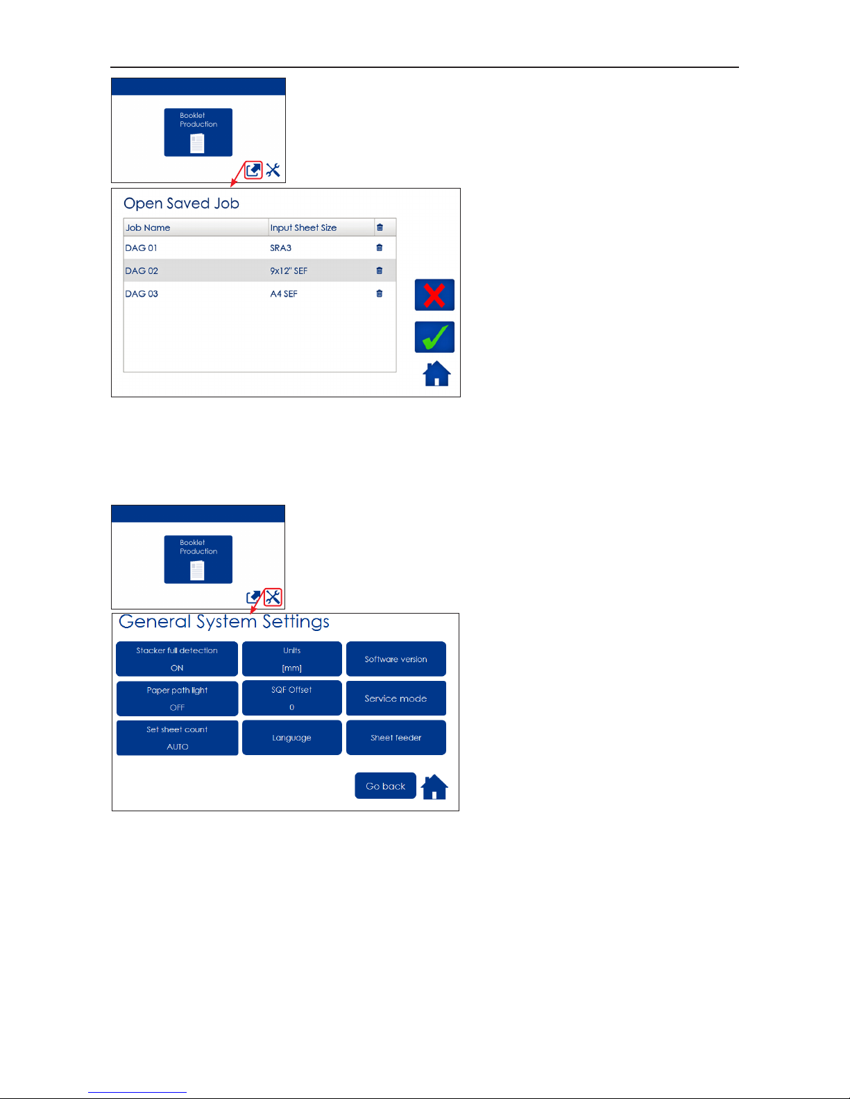
The Jobs Screen
Pressing the [Open Jobs] button in the
Start screen opens the Jobs screen.
From here you can open a saved job.
You can also open a saved job, custom-
ize it and store the new settings. Either
and save job settings. These procedures are described in section 4. Jobs.
General System Settings
Pressing the [Tools] button opens the
General Systems Settings screen. From
here you can change basic settings like
the display language, setting units from
millimetres to inches and more. See
section 3. Tools. for how to get around
in the Tools screen.

18
Options
BM350/500 Booklet Maker
Live logo
With a BM500 upgrade kit installed, the three stripes
below the user interface will signal status as follows:
Steady blue - when system is on and ready, process-
ing with or without paper ow
Alternating blue/yellow - Soft stop (staples low, cover
low, stacker full, waste bin full).
Alternating blue/red - Jam or malfunction
Not illuminated - System in power save mode or
switched of.
Live logo
The Please wait screen
While the machine sometimes needs
time to perform changes in settings, the
Please wait screen will be shown. The
machine will automatically return to the
Start screen after changes have been
implemented.
19
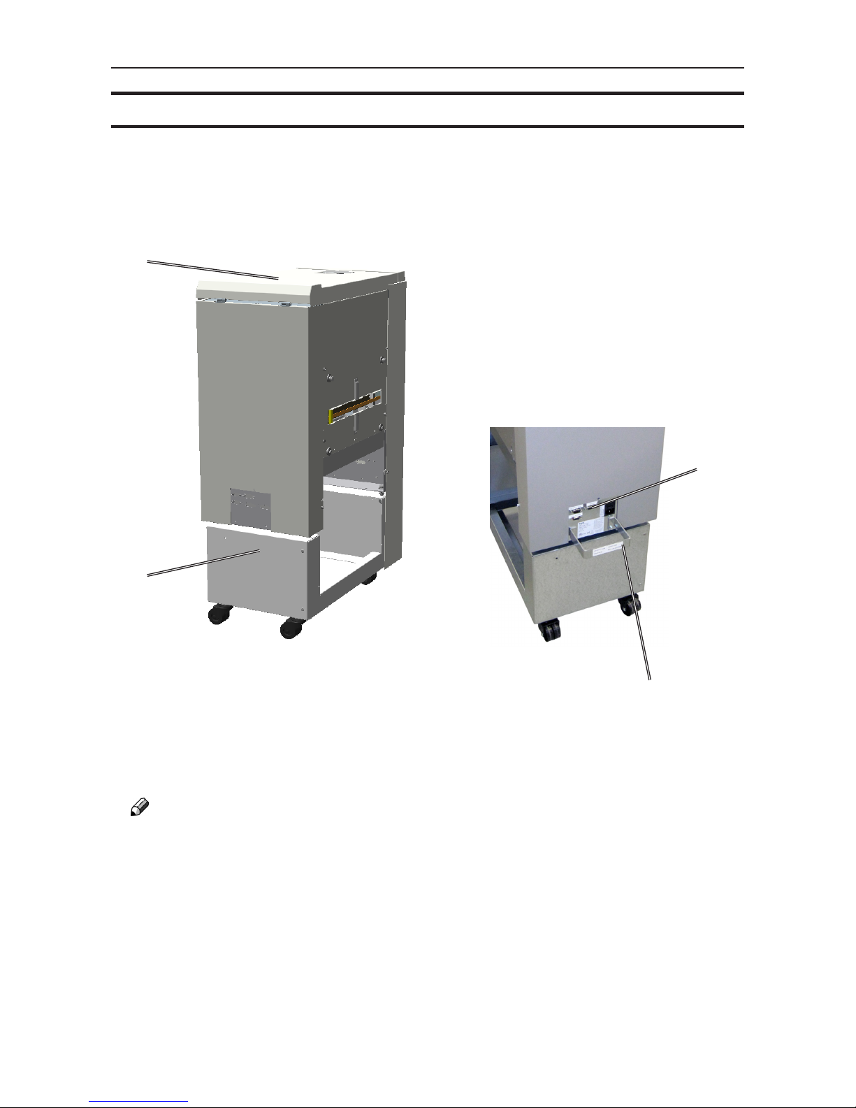
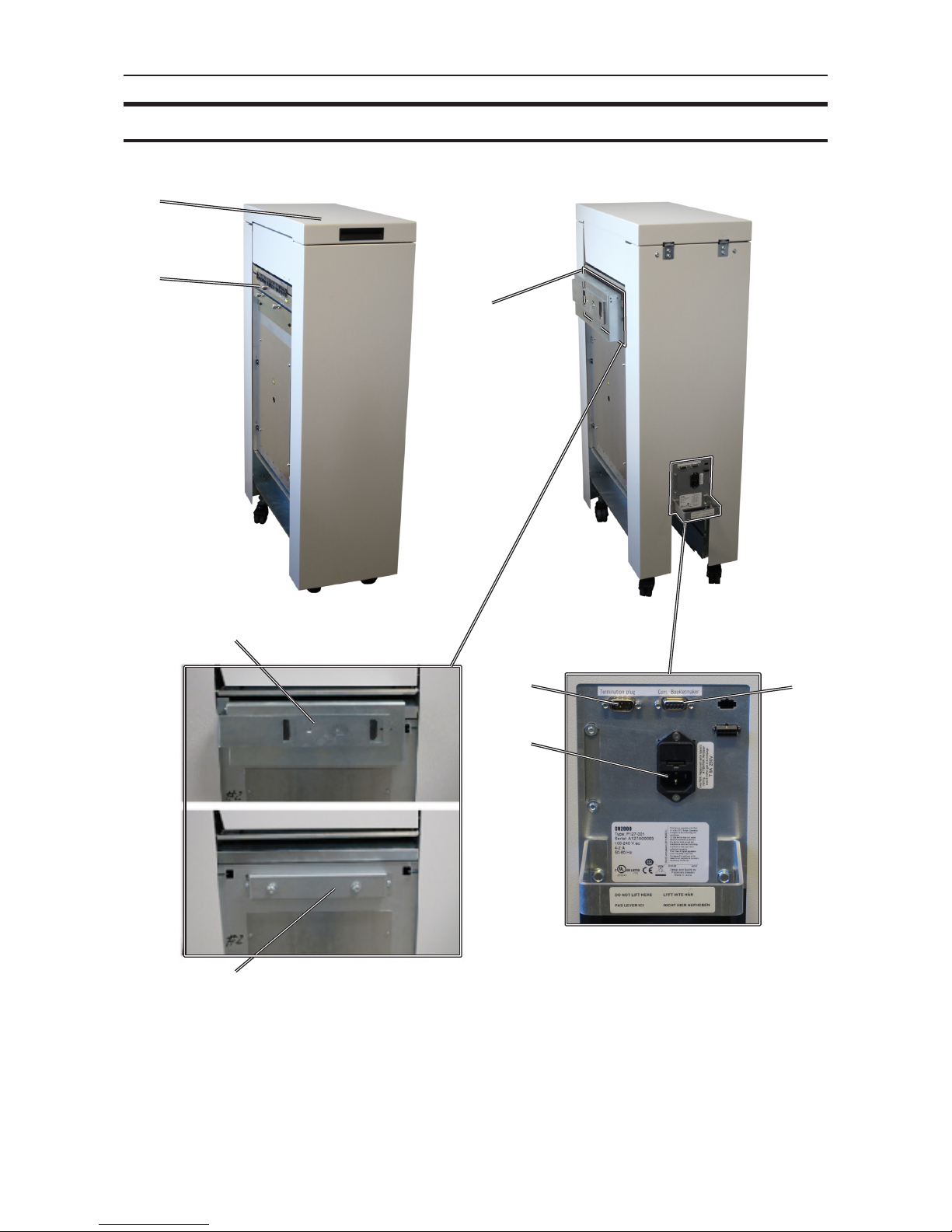
SQF500 Square Fold Module
3
1
1. Top cover
2. Base
3. Connections
4. Cable protector
2
4
NOTE:
How to connect cables, plugs and jumpers is described at the end of this manual.

20
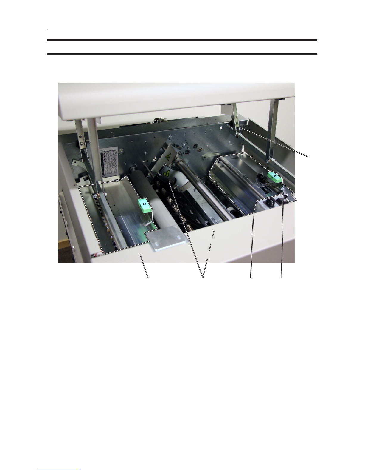
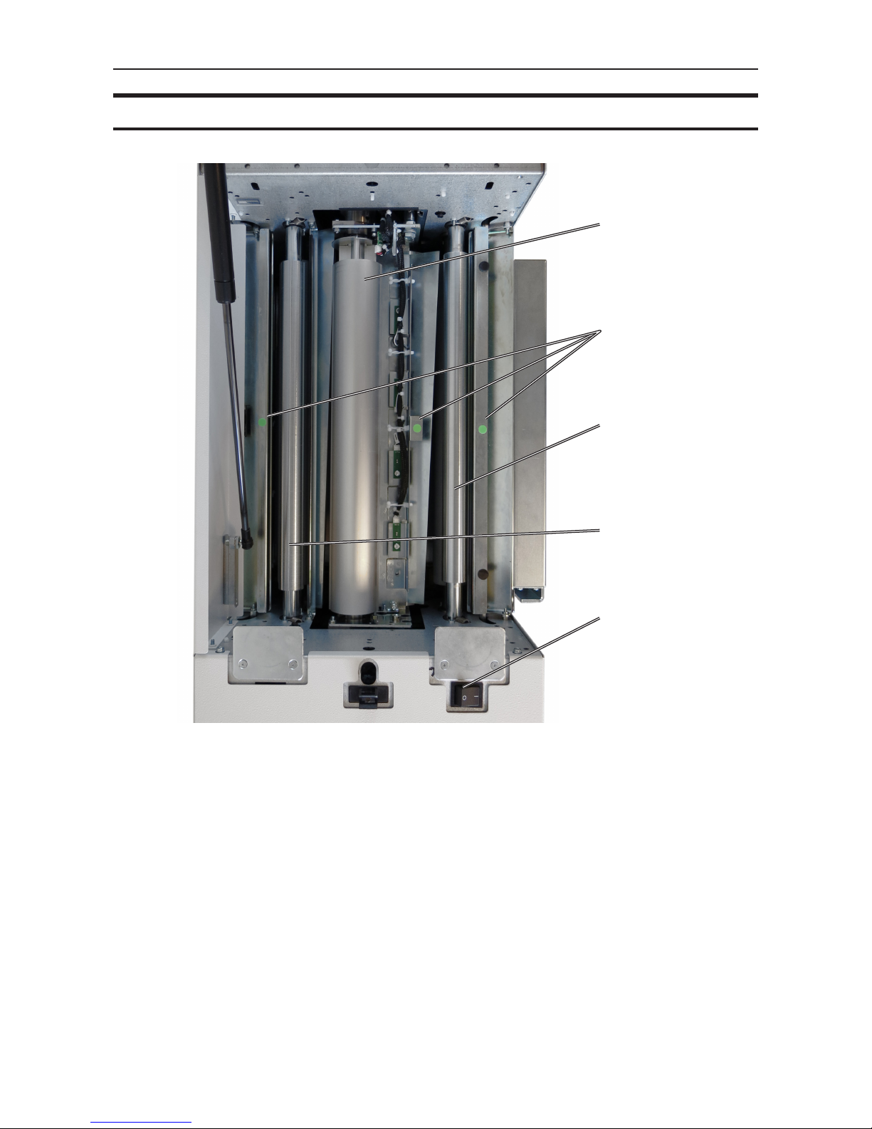
SQF500 Square Fold Module, continued
1. Lower feed belts
2. Upper feed belt release latch
3. Upper feed belts
1
2
3
Square Fold, top view, right hand upper feed belts is lifted up
The Square Fold interior has parts that you will come in contact with if a misfeed occur.
Left hand side upper
feed belt can not be
lifted fully
21
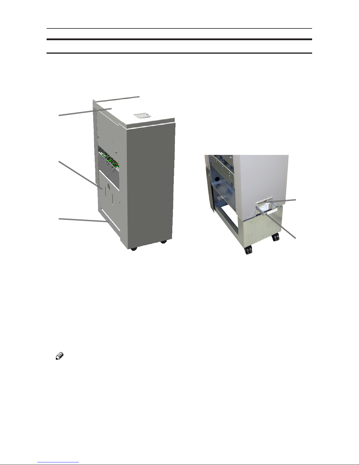
FTR500 Trimmer Module
1
2
4
1. Top cover
2. Trim bin
3. Base
4. Connections
5. Cable protector
3
5
NOTE:
How to connect cables, plugs and jumpers is described at the end of this manual.
22
FTR500 Trimmer Module, continued
The Trimmer interior has parts that you will come in contact with if a misfeed occurs.
6
1
2
3
4
8
7
5
1. Set counter
2. Trimmer stop
3. Exit drive release
4. Pre-cut compressing brackets
5. Upper knife
6. Transport belt
7. Trimmer fan
8. Infeed roller shaft
Trimmer, top view
23
CST500 Crease Trim Module
1. Top cover
2. Infeed slot
3. Upstream docking assembly
4. Slide door
1
2
3
4
24
CST500 Crease Trim Module, continued
1. Exit slot
2. Trim waste transport
3. Waste container
4. Connections
2
4
3
1

25
CST500 Crease Trim Module, continued
Connections bracket
NOTE
How to connect cables, plugs and jumpers is described at the end of this manual.
26
CST500 Crease Trim Module, continued
1. Exit section “D”
2. Bleed trimmer circular knives
3. Infeed Section “A”
4. Main switch
5. Counter
31 4
5
2

27
CST500 Crease Trim Module, continued
2 3 41
1 Waste chute(s)
2 Creaser registration adjustment
3 Bleed trimmer registration adjustment
4 Latch handle, slide
28
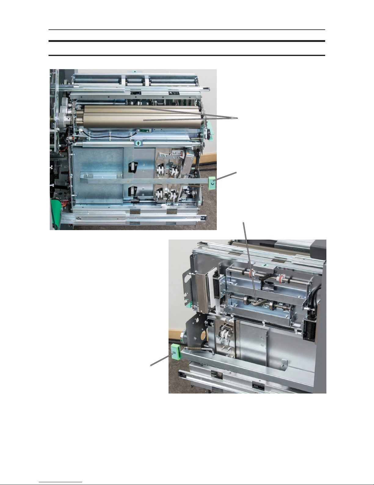
CST500 Crease Trim Module, continued
4
3
2
1
1 Creaser tools
2 Jam clearance bafe, ne registra-
tion, section “C”
3 Jam clearance bafe, coarse regis-
tration, section “B”
4 Rotator
29
CR500 Creaser Module
1
2
3
1. Top cover
2. Exit slot
3. Infeed area
4. Connector, upstream device e.g.
AF602/VF602/ACF510
4
6
5
5. Connector to downstream device e.g.
booklet maker
6. Main power connector
7. Docking bracket, ACF510
8. Docking bracket, AF602/VF602
7
8
30
CR500 Creaser Module, continued
5
2
3
4
1. Creaser tool
2. Jam clearance baffels, green dot
3. Infeed roller
4. Exit roller
5. Main power switch
1
 Loading...