


Morgana Systems Limited ▪ United Kingdom ▪ www.morgana.co.uk ▪ Telephone: ( 01908 ) 608888 ▪ Facsimile: ( 01908 ) 692399
Booklet Maker BM 2000
Operator Manual
Doc No. T10178

BOOKLET MAKER BM 2000
Operating Instruction
Booklet Maker Reference
Part no: 81248
Doc no: T10178
Rev. date: 14 January 2010

Note
The domestic environment is an environment where the use of broadcast radio and television
recievers may be expected within a distance of 10 m of the apparatus concerned.
WARNING:
Electromagnetic compliance:
This is a Class A product. In a domestic environment this product may cause radio
interference in which case the user may be required to take adequate measures.
The product (System) which is connected to this machine will be class A.
•
•
•

3
Introduction
This manual contains instructions on the operation and maitenance of this machine. To get
the maximum versatility from this machine all operators should carefully read and follow
the instructions in this manual. Keep this manual in a handy place near the machine.
Please read the Safety Information before using this machine. It contains information related to USER SAFETY and PREVENTING EQUIPMENT PROBLEMS.
How to read this manual
Notation conventions
Whenever necessary, the following points for attention are indicated in this manual.
WARNING:
Indicates a potentially hazardous situation which, if instructions are not followed, could
result in death or serious injury.
CAUTION:
Indicates a potentiality hazardous situation which, if instructions are not followed, may
result in minor or moderate injury or damage to machine or property.
Note
This sign refers to:
Remarks for making the operation much easier. You get practical hints or knowledge to
assist you in the machine operation such as:
Preparations required before operating
How to prevent papers from being misfed or damaged
Precautions required or actions to take after misoperation
Limitations like numerical limits, functions that cannot be used together or conditions,
under which a particular function cannot be used or obtained.
Information.
[ ]
Keys that appear on the machine’s display panel.
•
•
•
•
•
•

4
WARNING:
To avoid hazardous situations like for instance electric shock or danger while exposed
to moving, rotating or cutting devices, do not remove any covers, guards or screws
other than those specied in this manual.
Turn off the power and disconnect the power plug (by pulling the plug, not the cable) if
any of the following conditions exists:
You drop objects or spill something into the equipment.
You suspect that your equipment needs service or repair.
Your equipment’s covers has been damaged.
You notice unusual noises or odours when operating the equipment.
If the power cable or plug becomes worn out or otherwise damaged.
Before cleaning and care (unless otherwise specically instructed).
Electromagnetic compliance:
This is a Class A product. In a domestic environment this product may cause radio
interference in which case the user may be required to take adequate measures.
The product (System) which is connected to this machine will be class A.
•
•
•
•
•
•
•
•
•
•
•
Safety Information
When using this machine, following safety precautions should always be followed.
Safety during operation
General safety
WARNING:
Always connect the equipment to a properly grounded power source (wall outlet). If in
doubt, have the power source checked by a qualied electrician.
Improper grounding of the equipment can result in electrical shock. Never connect the
machine to a power source that lacks a ground connection terminal. This machine is
destined for specic purpose only. Any use going beyond this specic purpose is regarded as beyond the determination. The manufacturer will not be liable for damages
resulting from any use beyond the determination, unallowed operation, respectively.
The user alone bears the risk.
Do not make arbitrary changes or modications to the machine. The manufacturer will
not be liable for modications made at the machine on your own and damages result-
ing thereof. EC declaration of conformity and the mark CE will be invalidated, if you
make changes at the machine or at the individual components.
Do not override or bypass electrical or mechanical interlock devices.
The machine is to be used only by authorized and instructed persons. The responsibilities on operating the machine have to be strictly laid down and observed so that there
are no unclear competences regarding safety aspects.
Vent holes serve for air circulation to protect the machine from overheating. Make sure
that the holes are not covered.
Do not expose ngers or other parts of the body to moving, rotating or cutting devices
such as for instance between upper and lower trimmer knives.
Allways locate the equipment on a solid support surface with adequate strength tor
the weight of the machine.
•
•
•
•
•
•
•
•

5
Note
The indications like front and rear, left and right refer to the paper transport direction.
The operator manual always has to be available at the place of use of the machine.
In the interest of technical development the company reserves the right to make alterations to
specications without prior notice!
•
•
•
CAUTION:
The machine and its peripherals must be installed and maintained by a customer service representative who has completed the training course on those models.
Allways follow all warnings marked on, or supplied with, the equipment.
When you disconnect the power plug from the wall outlet, allways pull the plug (not the cable).
Disconnect the power cord before you move the machine. While moving the machine, allways
exercise care and make sure that the power cord will not be damaged under the machine.
Allways contact service if relocating the equipment.
Do not move the machine while the machine is running.
Do not open covers while the machine is running.
Do not switch of the power while the machine is running. Make sure the machine cycle has
ended.
Lay the power cord in a way that nobody will stumble over it. Do not place things on the cord.
Never attempt any maintenace function that is not specically described in this documentation.
Always keep magnets and all devices with strong magnetic elds away from the machine.
If the place of installation is air-conditioned or heated, do not place the the machine where it
will be:
Subject to sudden temperature changes.
Directly exposed to cool air from an air-conditioner.
Directly exposed to heat from a heater.
If the machine is not used over an extended period of time it should be unplugged to prevent
damage in the case of overload.
•
•
•
•
•
•
•
•
•
•
•
•
•
•
•
•
General safety, continued

Page intentionally blank

7
TABLE OF CONTENTS
What You Can Do With This Machine ............................................................................................5
Guide To Components ....................................................................................................................7
Booklet Maker ............................................................................................................................... 7
Options ........................................................................................................................................... 10
Trimmer .......................................................................................................................................10
SquareFolder .............................................................................................................................. 12
1. Basics
Booklet Maker ................................................................................................................................ 13
Turning On / Off the Power ......................................................................................................... 13
Control Panel .............................................................................................................................. 14
Staples, Staple Cartridge, Stapler Head & Clinchers .................................................................15
Removing / replacing Staple Cartridge..................................................................................................15
Removing / replacing Staple Cartridge, continued ................................................................................16
Removing / replacing Stapler Head.......................................................................................................16
Removing/replacing Stapler Head, continued .......................................................................................17
Changing Staple position and Narrow width Paper Sizes ..........................................................18
Changing Stapler and Clincher position ................................................................................................18
Setting up narrow width paper sizes .....................................................................................................19
Trimmer .......................................................................................................................................... 20
Emptying the Trim Bin ................................................................................................................. 20
2. Making Booklets
Changing Settings ......................................................................................................................... 21
General Procedure .....................................................................................................................21
Setting Paper Size ...................................................................................................................... 21
Selecting Standard Paper Sizes............................................................................................................21
Custom Paper Size ...............................................................................................................................22
Stapling and Folding ................................................................................................................... 22
Edge staple ...........................................................................................................................................23
Saddle staple.........................................................................................................................................23
Staple and Fold Alignment ....................................................................................................................23
Corner staple .........................................................................................................................................24
Trimming ..................................................................................................................................... 24
Selecting Trimming On or Off ................................................................................................................24
Adjusting the Cutting Margin .................................................................................................................24
SquareFolding ............................................................................................................................25
General..................................................................................................................................................25
Procedure ..............................................................................................................................................25
On-line / Off-line ............................................................................................................................. 26
On-line Mode .............................................................................................................................. 26
Off-line Mode .............................................................................................................................. 28
3. Admin
The Admin Screen ......................................................................................................................... 29
Paper size check ........................................................................................................................29
Mode, Safe / Fast .......................................................................................................................30
System Setup .............................................................................................................................30
Standard Paper Size ................................................................................................................... 31
Language ....................................................................................................................................31
Service ........................................................................................................................................ 31

8
4. Jobs
Storing and Deleting Jobs ............................................................................................................ 33
Storing a Job ............................................................................................................................... 33
Recalling a Job ........................................................................................................................... 34
5. Clearing a Paper Jam
Clearing a Paper Jam .................................................................................................................... 35
General ....................................................................................................................................... 35
Booklet Maker ................................................................................................................................ 36
Clearing a Paper Jam ................................................................................................................. 36
Inside the Booklet Maker .......................................................................................................................36
Trimmer .......................................................................................................................................... 38
Clearing a Paper Jam ................................................................................................................. 38
Clearing Jam in Input Area ....................................................................................................................38
Clearing Jam in Exit Area ......................................................................................................................39
SquareFolder .................................................................................................................................40
Clearing a Paper Jam ................................................................................................................. 40
Inside the SquareFolder ........................................................................................................................40
Exit Area ................................................................................................................................................40
6. Troubleshooting
Fault codes.....................................................................................................................................41
General ....................................................................................................................................... 41
Booklet Maker Fault Codes ........................................................................................................42
Remove stacked sheets ........................................................................................................................42
Too many sheets ...................................................................................................................................42
Check Staples .......................................................................................................................................42
Trimmer Fault Codes .................................................................................................................. 42
Close trimmer belts ...............................................................................................................................42
Waste Bin Full .......................................................................................................................................42
Booklet quality ............................................................................................................................... 43
Fold Quality ................................................................................................................................. 43
SquareFolding Quality ................................................................................................................ 44
7. General Remarks
Do’s And Don’ts ............................................................................................................................. 45
Placing Your Machine ...................................................................................................................46
Machine Environment ................................................................................................................. 46
Power Connection ......................................................................................................................46
Access to Machine ...................................................................................................................... 47
Maintaining Your Machines ..........................................................................................................48
Booklet Maker ............................................................................................................................. 48
Lubricating Staplers and Clinchers........................................................................................................48
SquareFolder .............................................................................................................................. 49
Cleaning Feed Belts ..............................................................................................................................49
Cleaning Square Folding Clamps..........................................................................................................50
8. Specications
Machine Specications ................................................................................................................. 51
Booklet Maker BM 2000 .............................................................................................................51
Trimmer FTR 2000 (option) ........................................................................................................52
SquareFolder SQF 2000 (option) ...............................................................................................52

9
What You Can Do With This Machine
The Booklet Maker BM 2000, Trimmer FTR 2000 and SquareFolder SQF 2000 form a
booklet making system that works on-line with Feeder/Collators.
The sheets from the Feeder/Collator are transported into the BM 2000 Booklet Maker and
collected in the stapler area of the BM 2000 Booklet Maker. The Booklet Maker now jogs
and then staples the set. The set is then transported further to the folding area where the
set is folded into a booklet and then fed out to the belt stacker.
When a larger number of sheets are folded an effect called creeping occurs. In order to
rectify creep, the FTR 2000 Trimmer (optional) can be connected to the Booklet Maker.
The booklets are then transported from the Booklet Maker into the Trimmer where the front
edge (face) will be cut off.
Another option, the SQF 2000 SquareFolder, can be installed if a FTR 2000 Trimmer is
installed on the BM 2000 Booklet Maker. The prints, which have been stapled, folded and
trimmed will be fed into the SQF 2000. The SQF 2000 will atten the spine of the booklet
into a square shape. The booklets will, after passing through the SQF 2000, have the look
of a perfect bound book.
The booklets are then fed out to the Belt Stacker.
FTR 2000 Trimmer (option) BM 2000 Booklet MakerSQF 2000 SquareFolder (option)
Belt Stacker

10
The entire BM 2000 Booklet making system is controlled from a single control panel on the
Booklet Maker. The control panel has only six buttons which will allow you to easily set up,
adjust and operate the complete system.
The buttons are multi functional, meaning that the
function of each button depends on the information
displayed.
For example: In this screen, the icon next to button 1
indicates you will go up one level in the menu when
the button is pressed.
Example 2: In this screen, button 1 has no function.
Example 3: Pressing button 1 here will answer “No”
to the question on the screen.
1
2
3
4
5
6
Buttons
1
2
3
4
5
6
1
2
3
4
5
6

11
Guide To Components
1
4
2
1 Control panel
2 Top cover
3 Power switch
4 Infeed assembly
3
Booklet Maker
5 Hand feed tray (optional)
6 Belt Stacker
7 Belt Stacker Cover
8 Hand feed slot (for on-line mode)
7
6
5
8

12
Booklet Maker, continued
5
4321
6
7
8
1 DFA. Not in use.
2 Not in use.
3 CAN In: Termination socket /
Communication with
Feeder/Collator
4 CAN Out: Termination socket /
Communication with FTR 2000
5 Power receptacle
6 Power out to SQF 2000
7 Interlock jumper
8 Interlock jumper / Power out to FTR
2000

13
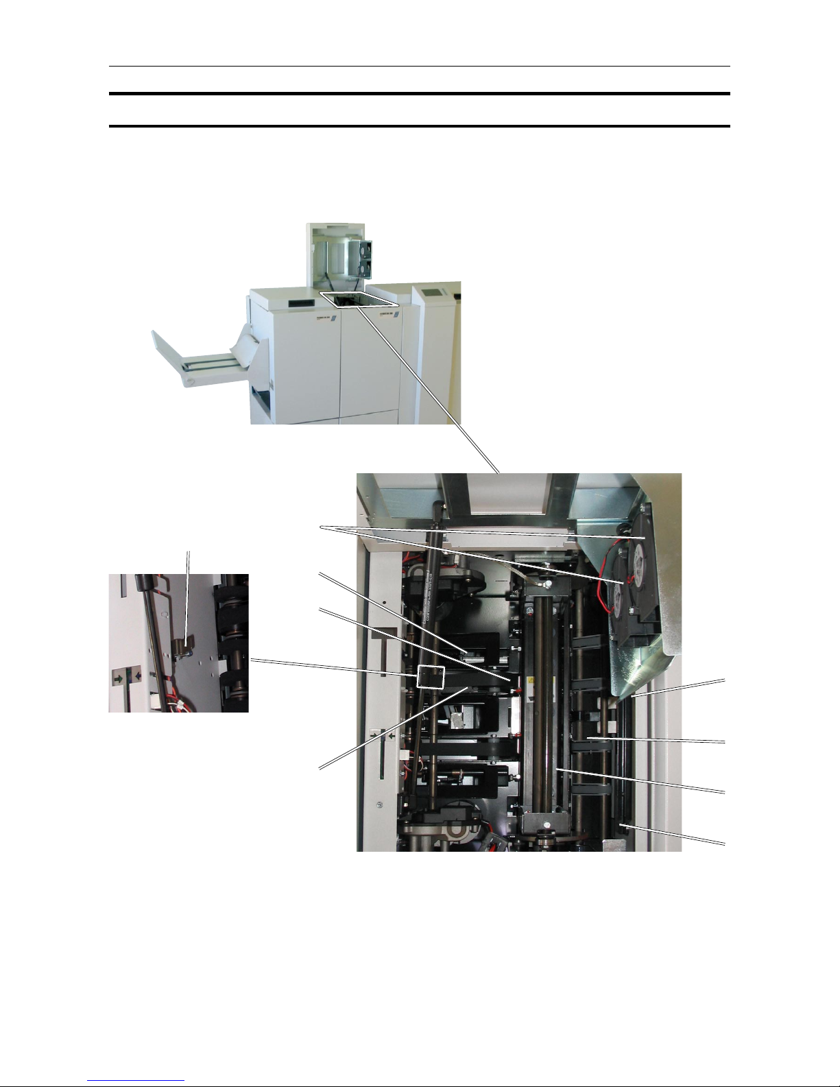
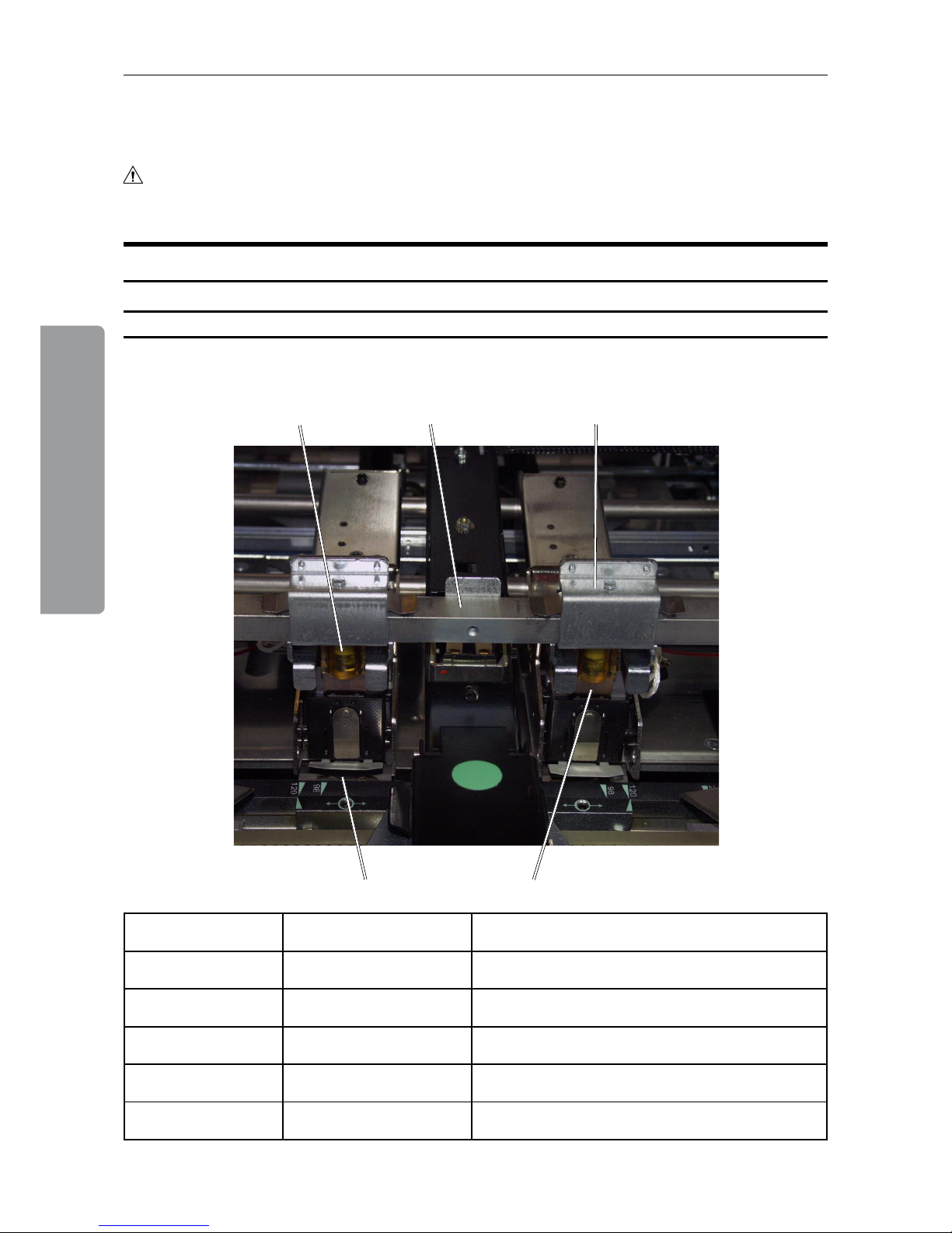
1 Tool box
2 Ball cage
3 Fold adjust lever, right side
Left side not shown in picture
4 Alignment tool, stapler assy.
5 Cartridge locking levers
6 Stapler lift brackets
7 Side guide extension
8 Thumb screw for Side guide ex-
tension
9 Stapler heads
10 Side guides
11 Guide
12 Screws for Stapler assy.
13 Staple detection leads, one on each
stapler head
14 Locking pin, one on each stapler head
15 Clincher, left side. Right side not shown
in picture
Booklet Maker, continued
9
7
14
8
11
5
2
3
12
10
6
7
8
Booklet maker,
top view
1
13
15
4

14
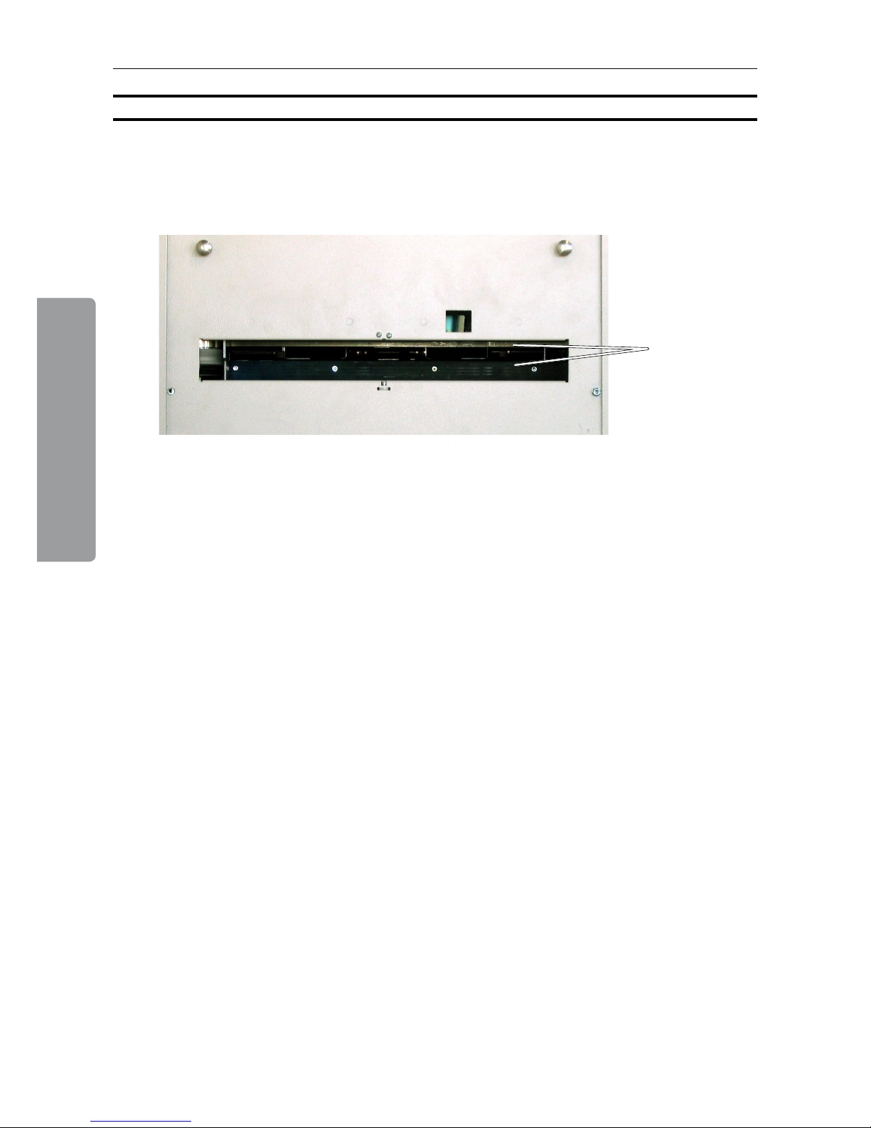
Trimmer
1
2
1 Top cover
2 Trim bin
Options
15
Trimmer, continued
8
1
9
6
7
4
5
3
1 Trimmer fan
2 Outfeed latch
3 Transport belt
4 Exit compression brackets
5 Trimmer stop
6 Docking bracket
7 Infeed roller shaft
8 Knives (not visible in picture)
9 Infeed latch
Trimmer, top view
2

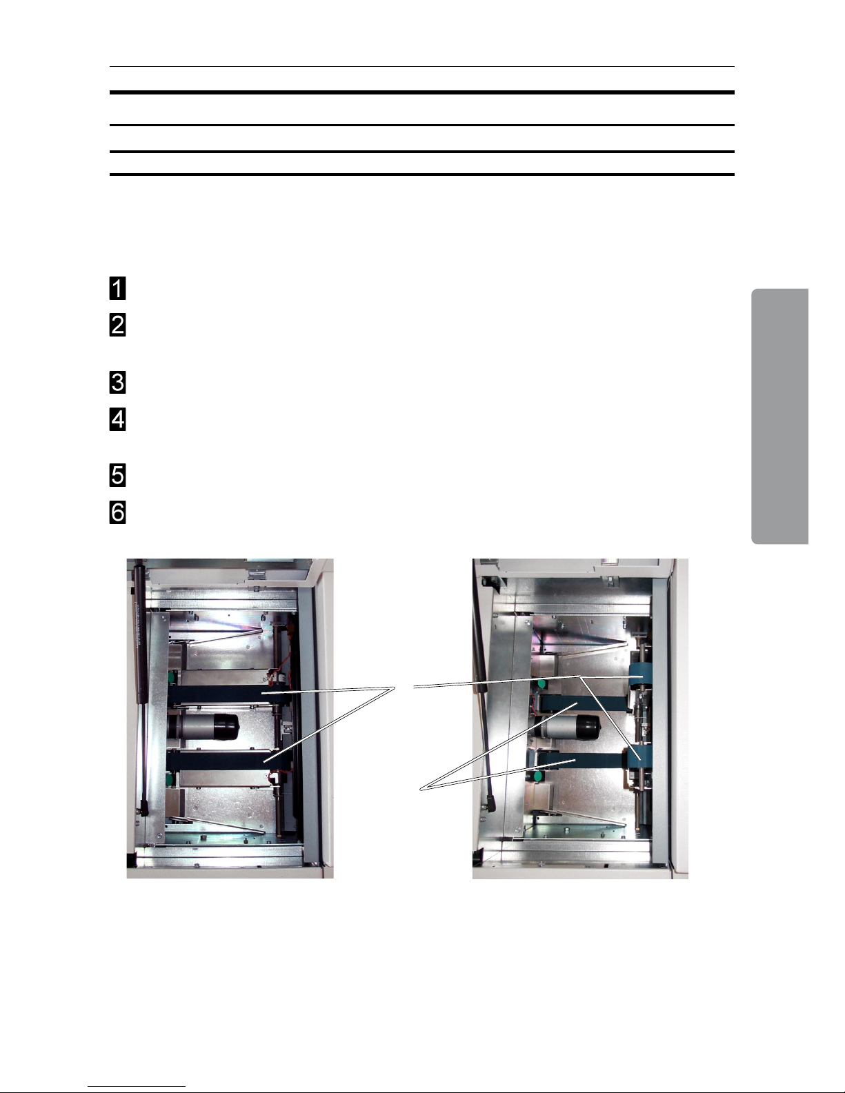
16
1
1 Top cover
2 Upper feed belts (lifted position)
3 Docking bracket (not visible in picture
5 Lower feed belts
4 Latches
SquareFolder
5
2
4
3
SquareFolder,
top view

17
Plug the Booklet Maker power cord into the wall outlet.
Trimmer (optional) and SquareFolder (optional) are powered from the Booklet Maker.
Open the Top cover (A).
Set power switch (B) on Booklet Maker to ON position.
Note
The Power switch also controls Trimmer (optional) and SquareFolder (optional).
Close the Top cover.
Booklet Maker
Turning On / Off the Power
B
A
1. Basics
1. Basics
18
Control Panel
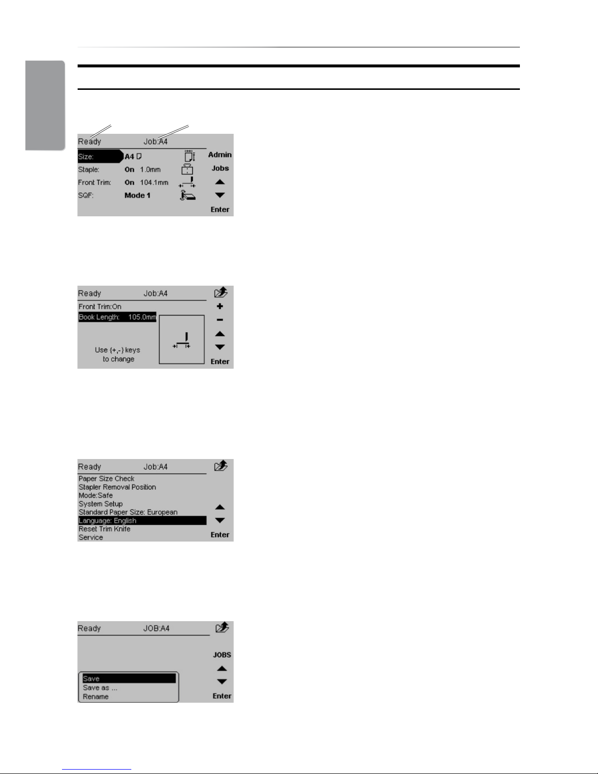
The Main screen.
When the system power is switched on the Main
screen will be shown. Here you will nd information
showing the actual set up. From this screen you can
also access other screens, that will help you operate
the complete BM 2000 Booklet making system.
At the top, throughout the screens you can see the
current state of the machine and the current job.
State Current Job
The Jobs screen.
Pressing the [Jobs] button in the Main screen opens
the Jobs screen. From here you customize and
save job settings. Press [Jobs] again and you can
load previously saved jobs. These procedures are
described in section 4. Jobs.
The Admin screen.
Pressing the [Admin] button in the Main screen takes
you to the Admin screen. From here you can change
the display language, set paper size standard and
more. See section 3. Admin, for how to navigate in
the Admin screen.
Changing settings.
To change or adjust settings; Select an item in the
Main screen with the [arrow] button and press the
[Enter] button. For example you can ne adjust
the trimming, change stapling mode or set the
SquareFolder to the correct mode. Settings are
explored more thoroughly in section 2. Making
Booklets.
19
1. Basics
Staples, Staple Cartridge, Stapler Head & Clinchers
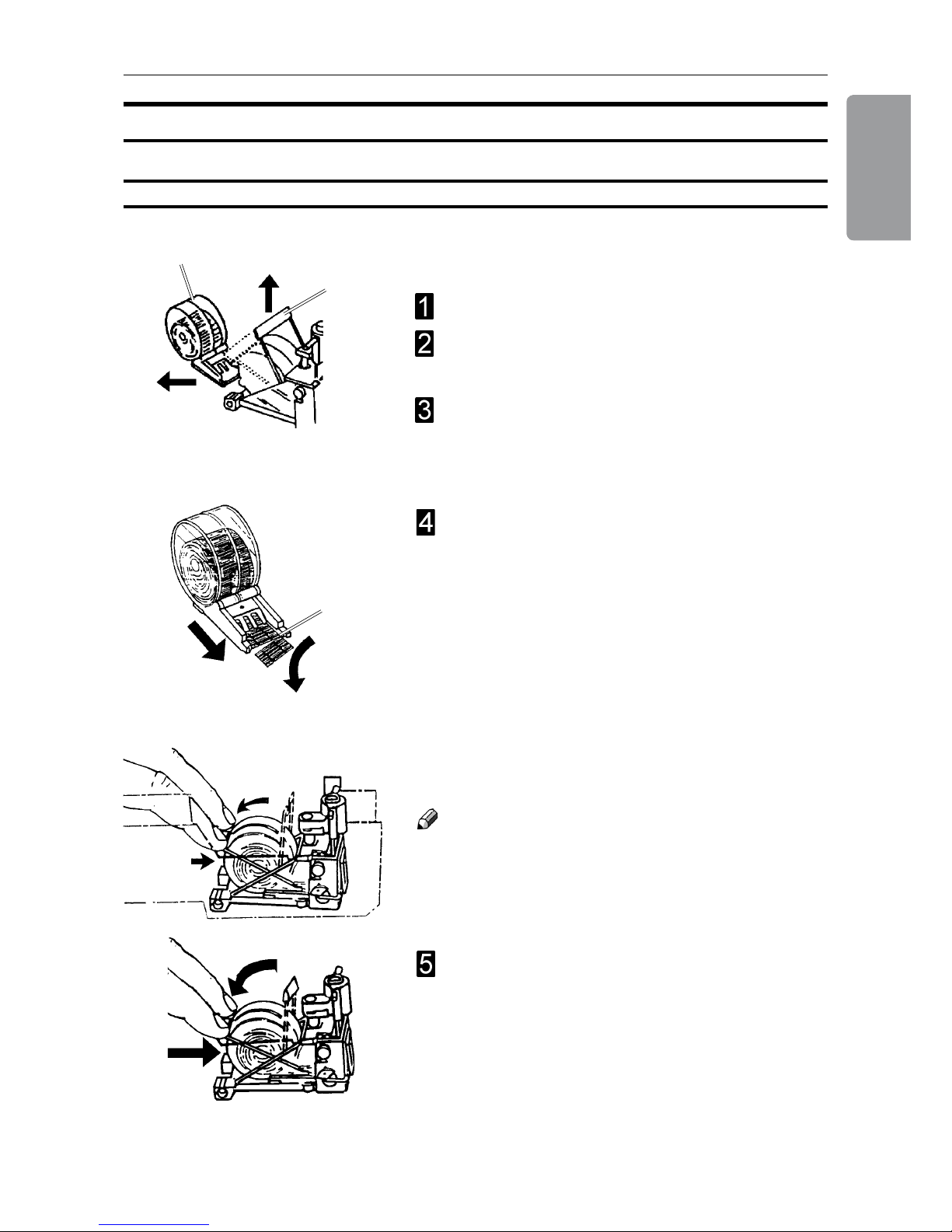
Removing / replacing Staple Cartridge
A
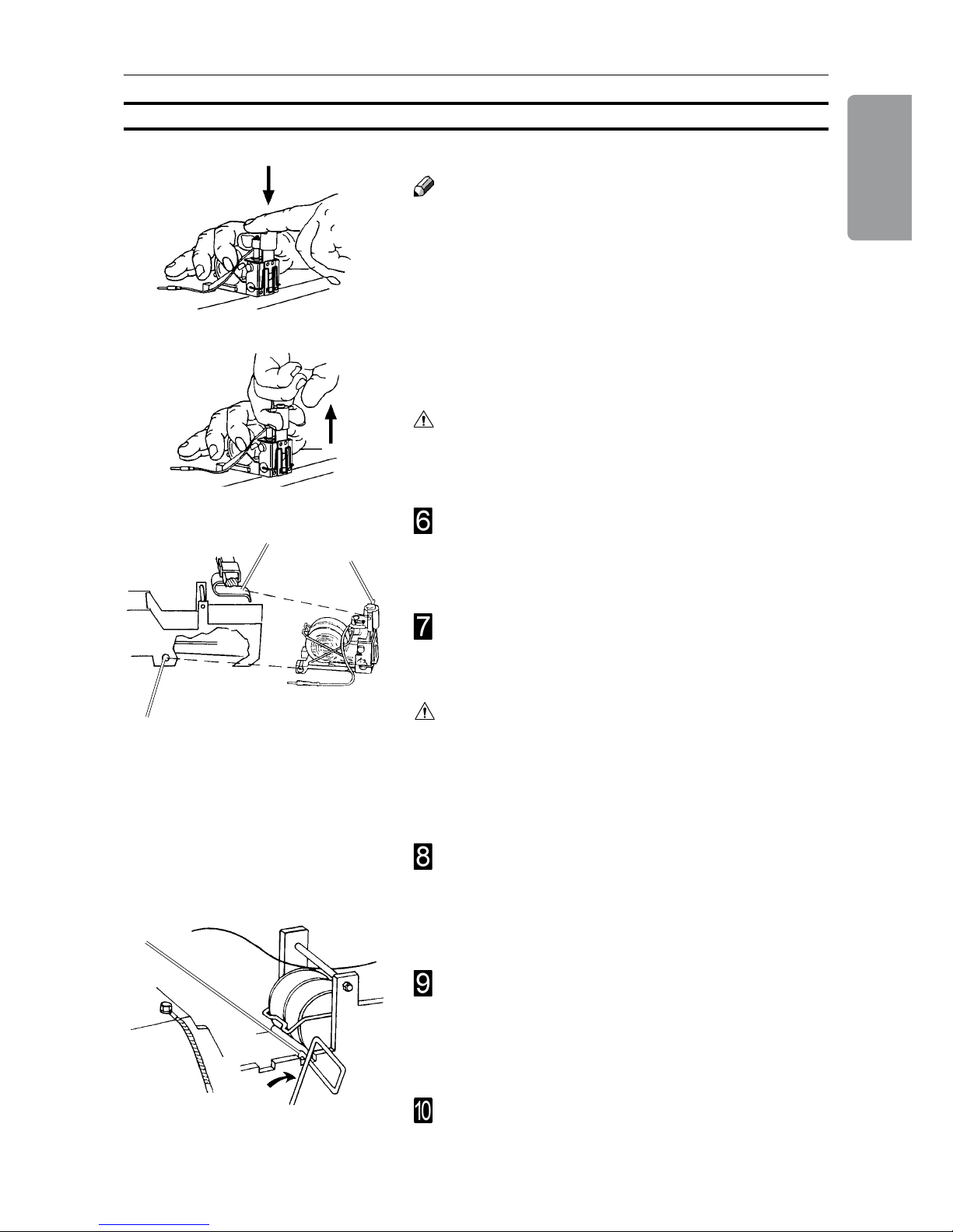
You may remove and replace the staple cartridge
while the stapler head assembly is in place.
Open the top cover.
Raise the staple cartridge locking lever (A) as
indicated in the drawing.
Gently twist the staple cartridge (B) from side to
side, and pull out the staple cartridge (B) from the
stapler head.
B
If the staple cartridge is empty or allmost empty*,
discard it and replace it with a new one. Before
replacing the cartridge, pull at least 20 mm of the
staples out and tear off at the staple tear line (C)
which is marked on the cartridge. If there has been a
misfeed, and the cartridge still contains staples, pull
20 mm of staples out of the cartridge and tear off at
the stapler tear line. Check that the rst staple is at.
If not, tear off another 20 mm, using less force.
*containing 300 staples or less
C
Insert the cartridge into the stapler head with the
staples facing towards the head mechanism. The
cartridge should be placed at on the slide on the
bottom of the stapler head. Push the cartridge rmly
into the stapler head and keep holding it pressed.
While holding the staple cartridge rmly pressed
into the stapler head, push down the cartridge
locking lever.
Note
It is important that the cartridge not is allowed to move
away from the stapler head before the locking lever
is in engaged. If that occurs, remove cartridge and
again tear off 20 mm of staples along the staple tear
line before inserting the cartridge.
Replacing the staple cartridge
1. Basics
20
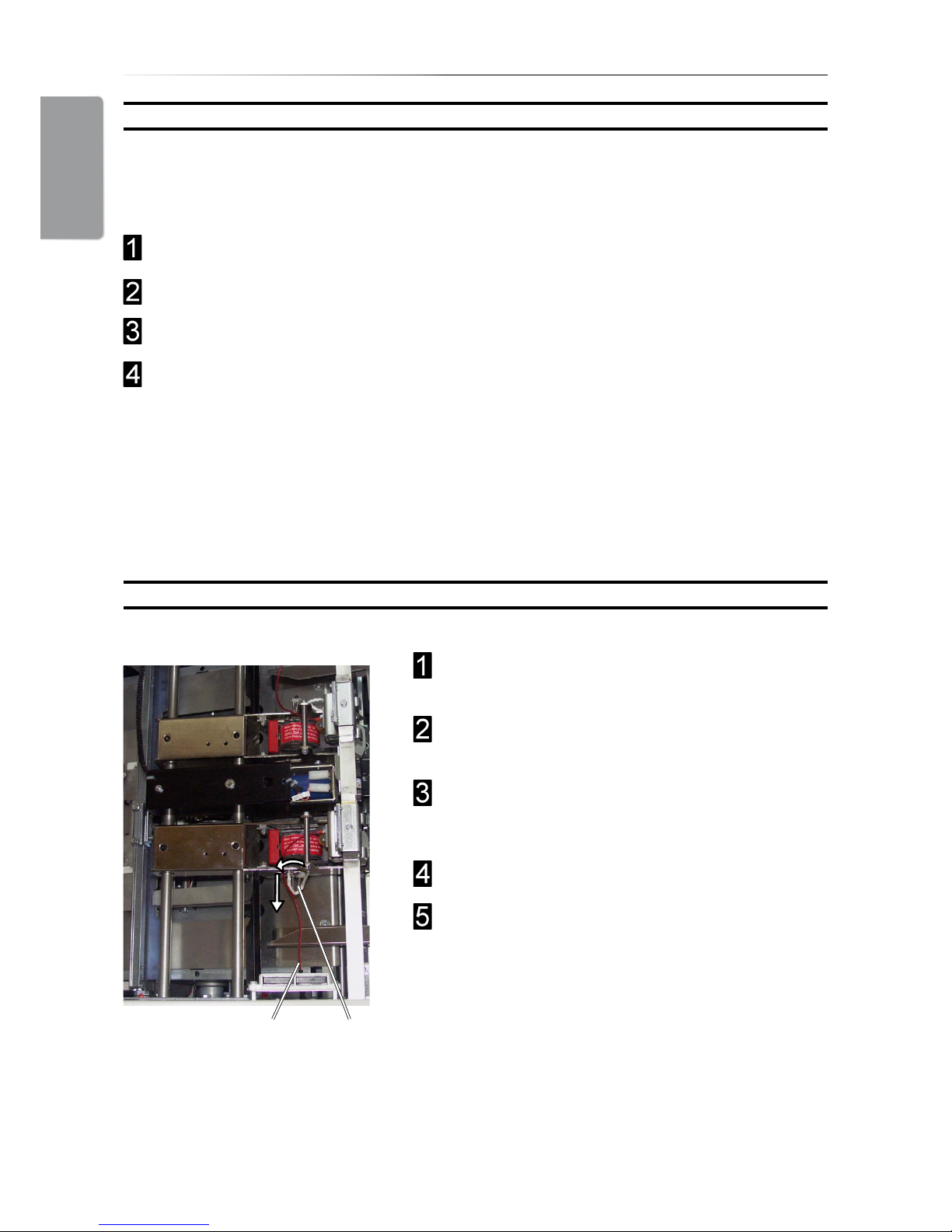
Removing / replacing Stapler Head
Removing / replacing Staple Cartridge, continued
After staple jam or empty staple cartridge has been detected, the BM 2000 will
automatically advance and feed staples. This feature is called staple recovery. Follow
procedure below after a staple jam or empty staple cartridge indication.
Follow step 1-6 on the previous page.
Close the top cover.
Feed in a four page set. The staple recovery will commence now.
Now the BM 2000 has recovered and production can continue. In case problem
persists and no staples were fed, the display will indicate that again.
In such a case:
Repeat this procedure. If problem still persists, perform the Removing/replacing Stapler
Head procedure.
Select A3 (11x17”) paper size to facilitate
removing or replacing the stapler head.
From the Main Screen press [Admin]. Select
Stapler removal position and press [Enter].
Rotate the locking pin (A) towards the folding
area and remove the locking pin from the stapler
head assembly.
Disconnect the staple detection lead (B).
Push the stapler head towards the in-feed side,
out of the stapler head assembly.
AB
21
1. Basics
Before inserting the stapler head, centre the
stapler lift bracket (D) over the area that will
receive the stapler head. Ensure that the staple
driver post (E) is in its uppermost position.
Place the stapler head back into the BM 2000.
The driver post arm (E) must be placed into the
stapler lift bracket (D).
Removing/replacing Stapler Head, continued
Note
Whenever you remove a stapler head, be sure to
manually eject some staples before replacing it in the
BM 2000. To do this, rest the stapler head on a rm
surface (for example, the top of a table) and actuate the staple driver post up/down through full travel.
Do this a number of times to ensure that the staples
are ejected on each down movement. If you need
to change the staple cartridge, see previous section,
removal/replacement of staple cartridge.
Warning
When manually ejecting the stapler, stay clear from
stapler output area.
Secure the locking pin by rotating it towards the
in-feed side until it snaps in position (G). Check
that the stapler head is correctly mounted by
pushing the stapler head towards the infeed area.
If it is still loose, it is not correctly mounted.
Insert the staple detection lead (C) into its socket.
Press on the lower front edge of the stapler head
to align the hole (F) in the stapler bracket with the
hole in the stapler head. Insert the locking pin (B)
so that it engages the stapler head and the metal
sides of the stapler assembly.
Caution
If the driver post arm is not correctly positioned into
the stapler lift bracket (D) it will cause permanent
damage to the stapler head as well as the bracket.
Subsequently, also future correctly mounted stapler
heads will be damaged.
E
D
F
G
1. Basics
22
Changing Stapler and Clincher position
Use the allen key in the tool box at position (B) to
loosen each anvil (A).
Move each anvil (A) to the desired position and
tighten the set screws (B) using the allen key.
Use the allen key in the tool box at position (C) to
loosen each stapler assembly (D).
Position each stapler assembly (D) over the
corrresponding anvil (A) and use the alignment
tool (E) found on the right machine frame to
centre each stapler assembly over each anvil (A).
Thighten the screws (C).
Caution
It is very important to align the stapler assembly
correctly over the anvil.
B
A
A
C
Changing Staple position and Narrow width Paper Sizes
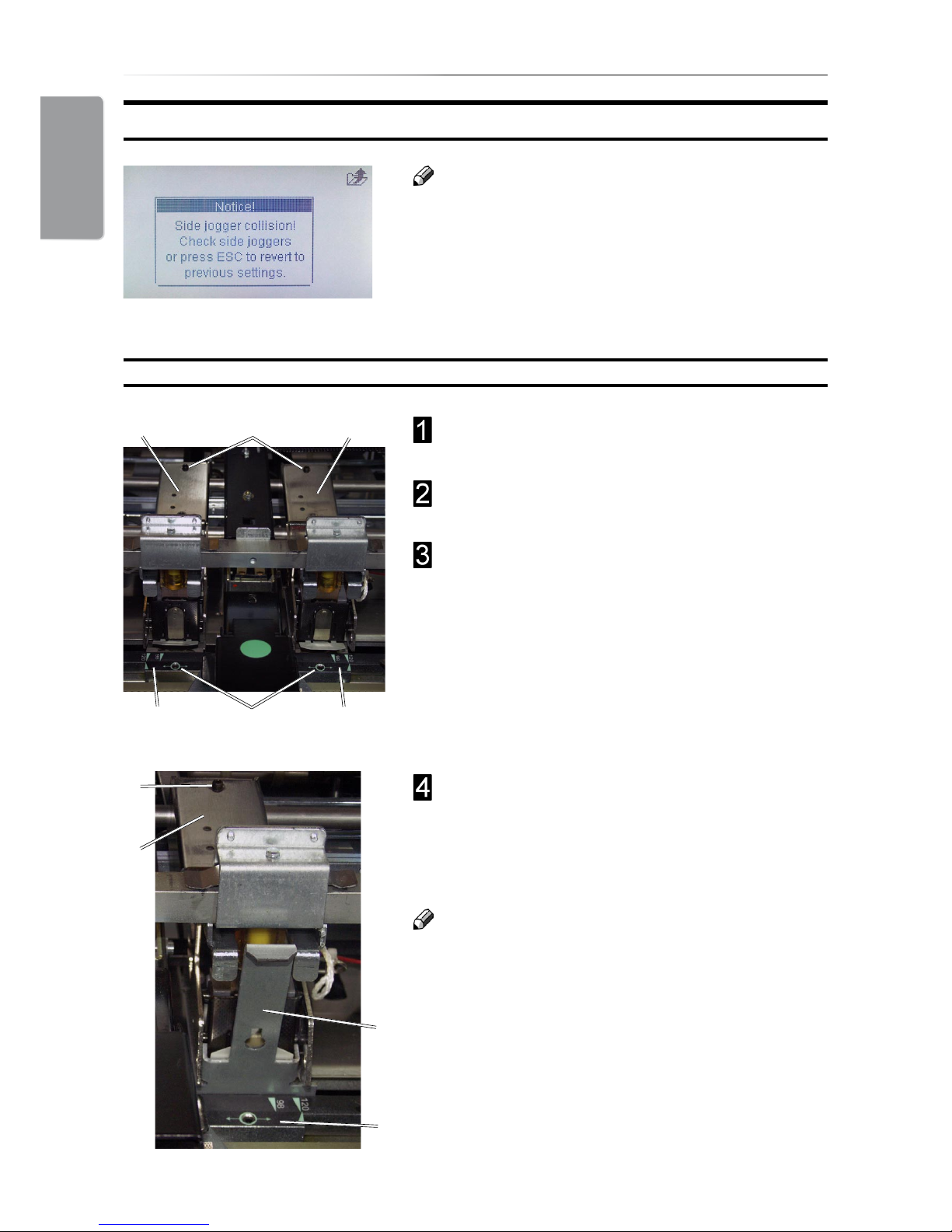
Note
Some situations require that the stapler assemblies
are repositioned and/or that the side guide
extensions are removed. This to avoid that the side
guide extensions collide with the stapler assembly.
If such collision should occur, the message “Side
jogger collision. Check side joggers. Width setting
reseted” will be shown in the control panel.
D D
E
A
C
D

23
1. Basics
Setting up narrow width paper sizes
If you are setting up a paper width less than 210 mm
(8.27”) and the stapler assemblies are in the default
position, the side guide extensions (B) must be removed.
Loosen thumb screws (A), one on each side
guide.
Remove both side guide extensions (B).
If required, also move the Stapler and Clincher
positions closer together. See “Changing Stapler
and Clincher position” above.
Note
Make sure to re-install the side guide extensions
after the run. Otherwise paper jams might occur.
B
A
F
The anvil positioning scale (F) indicates the distance,
in millimetres, from centre to centre (cc) of the staples.
Type of nishing Paper format Setting (cc)
booklet making 5.5”, CD 98
booklet making A5 98
booklet making 8.5”, A4 120 (default position)
booklet making 11”, A3 120 or 200
edge stapling 11”, A4 144 (recommended)
corner stapling 11” 255 (recommended)
corner stapling A4 273 (recommended)
Note
Using other settings could result in poor staple/fold
result.
If required, also remove the side guide extensions.
See “Setting up narrow width paper sizes below.
1. Basics
24
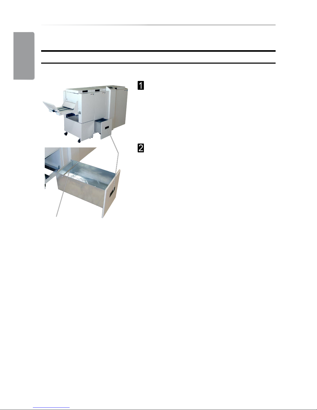
Emptying the Trim Bin
Remove the trim bin by pulling handle (1).
1
2
Trimmer
Lift out the Trim Bin by grasping the rod (2) and
handle (1).

25
2. Making Booklets
Setting Paper Size
Selecting Standard Paper Sizes
Changing Settings
Changing settings can be performed in two ways. Temporary, which means that the changes
will remain until a new job is loaded or permanent, which means that the changes will be
stored as a job. This job can later be recalled.
Procedure for temporary changes:
From the Main screen, select the option you wish to change and press the [Enter] button.
Conrm changes by pressing the [Enter] button in the next screen.
Procedure for permanent changes:
Same procedure as for temporary changes. But, in addition, from the Main screen, press the
[Jobs] button to reach the Jobs screen. Select Save if you want to incorporate the change in
the current job or Save as... if you want to store the changed job as a new job.
Note
Choose either of the above mentioned procedures when changing size, stapling, trimming
or Square folding as follows.
From the Main screen, select [Size] and press the
[Enter] button.
General Procedure
Current Size is highlighted. Press [+] or [-] to scroll
within the preset paper sizes. Press [Enter] to select.
Note
Some combinations of paper size and staple mode
are not possible. If the message “Illegal settings.
Please choose another setting combination” is
shown, correct either paper size or stapling mode.

2. Making Booklets
26
Custom Paper Size
From the Main screen, select [Size] and press the
[Enter] button.
Select [Length] or [Width] and press the [+] or [-]
button to correct paper size. The paper size can be
changed in increments of 0.1 mm or approx.. 0.01
inches. Press the [Enter] button to conrm.
Note
In the main screen the paper size is shown without
the decimal point. The machine has however
recognised and set up according to the exact size
including the decimal point.
Stapling and Folding
From the Main screen, select [Staple] and press the
[Enter] button.
There are four different stapling modes; [Off],
[Edge staple], [Saddle staple] and [Corner staple].
With the Staple line highlighted, press [+] or [-] to
choose stapling option.
Note
Some combinations of paper size and staple mode
are not possible. If the message “Illegal settings.
Please choose another setting combination” is
shown, correct either paper size or stapling mode.

27
2. Making Booklets
Edge staple
Select [Edge staple] when you want to make edge
stapled sets. Press the [Enter] button to conrm.
Note
Finished sets will be delivered to the Trim Bin in the
Trimmer.
Saddle staple
Select [Saddle staple] when you want make saddle
stapled booklets.
Staple position and fold line can be adjusted both
individually and together. If adjustment is needed,
see Staple and Fold Alignment below. Otherwise,
press the [Enter] button to conrm.
If the booklets exiting the system do not have the
staples centred on the fold, or if stapling position is
desired on the top or bottom of the spine, that can be
adjusted from the control panel.
With Fold correction highlighted, press [+] or [-] to
move staple positioning on the spine. Press the
[Enter] button to conrm.
Note
This adjustment can also be done during booklet
making.
If the booklet fold line is not in the centre of the sheet,
or if it is desirable to move the fold line to match the
print, that can be adjusted from the control panel.
Contrary to the above situation, this adjustment
moves both the staple and fold together.
With Staple Fold Pos highlighted, press [+] or [-] to
move the staple and fold line position. Press the
[Enter] button to conrm.
Staple and Fold Alignment

2. Making Booklets
28
Corner staple
Select [Corner staple] when you want to make corner
stapled sets. Press the [Enter] button to conrm.
Remove either stapler head and position the
other stapler head and clincher as needed. See
section 1. Basics.
Note
Finished sets will be delivered to the Trim Bin in the
Trimmer.
Trimming
Selecting Trimming On or Off
Press the [+] or [-] button to change Front Trim on or
off. If the cutting margin i.e. the length of the booklet
needs to be adjusted, see Adjusting the Cutting
Margin below. Otherwise, press the [Enter] button to
conrm.
From the Main screen, select Front Trim and press
the [Enter] button.
Adjusting the Cutting Margin
With [Book length] highlighted, press [+] or [-] adjust
the cutting margin. The measurement displayed is
the width of the nished, trimmed booklet. Press the
[Enter] button.
Note
Even though it is possible to set a certain cutting
margin in the control panel, the Trimmer has
mechanical limits. The minimum length of a trimmed
booklet is 120 mm (4 3/4”) and the maximum length
is 220 mm (8 11/16”).

29
2. Making Booklets
SquareFolding
General
The SquareFolder has seven different settings; [Off], [Mode 1], [Mode 2], [Mode 3] [Mode
4], [Mode 5] or [Auto].
In [Auto] mode, the Booklet Maker detects how many sheets there are in the booklet, and
automatically set the SquareFold to the correct mode.
Note
When the SquareFold is set to [Auto] and the booklet has less than approximately 6 sheets/
booklet, the SquareFold will bypass the Square folding action, transporting the booklet out
to the Belt stacker.
Use the manual modes to override the auto function. There are ve different manual modes
to select from.
Mode 1: Approximately 6 - 10 sheets.
Mode 2: Approximately 11 - 15 sheets.
Mode 3: Approximately 16 - 20 sheets.
Mode 4: Approximately 21 - 25 sheets.
Mode 5: Approximately 26 - sheets.
Select [Off] to bypass the SquareFold
Procedure
From the Main screen, scroll down to SQF and
press the [Enter] button.
Select [Auto], [Mode 1], [Mode 2], [Mode 3] or [Off]
with the [arrow] button and press the [Enter] button.

2. Making Booklets
30
Make necessary settings according to “Changing
settings” earlier in this section.
The Booklet Maker is now in stand-by and will
start automatically when a set is fed from the
Feeder/Collator.
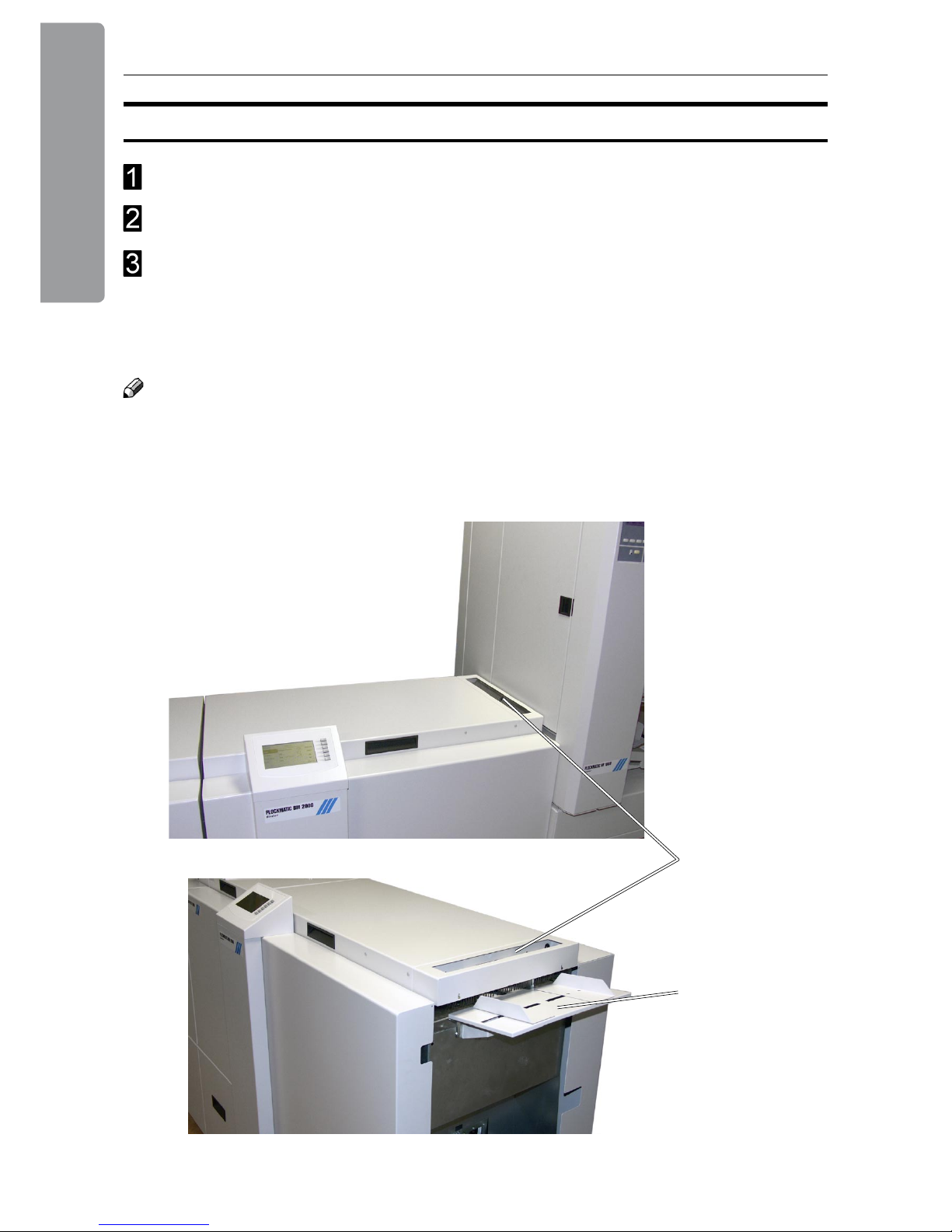
Setup the Feeder/Collator according to the
Feeder/Collator operating instruction
Press the yellow button (A) on the Feeder/
Collator to send a calibration set from the Feeder/
Collator to the Booklet Maker.
The message “Open cover and check set!” will be
shown in the Booklet Maker control panel.
Open the Booklet Maker top cover and check the
set regarding number of sheets and paper size. Try
to move the sheet/set as illustrated to detect play.
If there is play, adjust the paper size setting in the
Booklet Maker accordingly. Send a calibration set
again and check that there is no play.
Continue on next page
On-line / Off-line
The Booklet Maker can be operated in two modes. On-line mode, when used together with
the Feeder/Collator, or off line mode, when used for hand feeding.
A
On-line Mode
31
2. Making Booklets
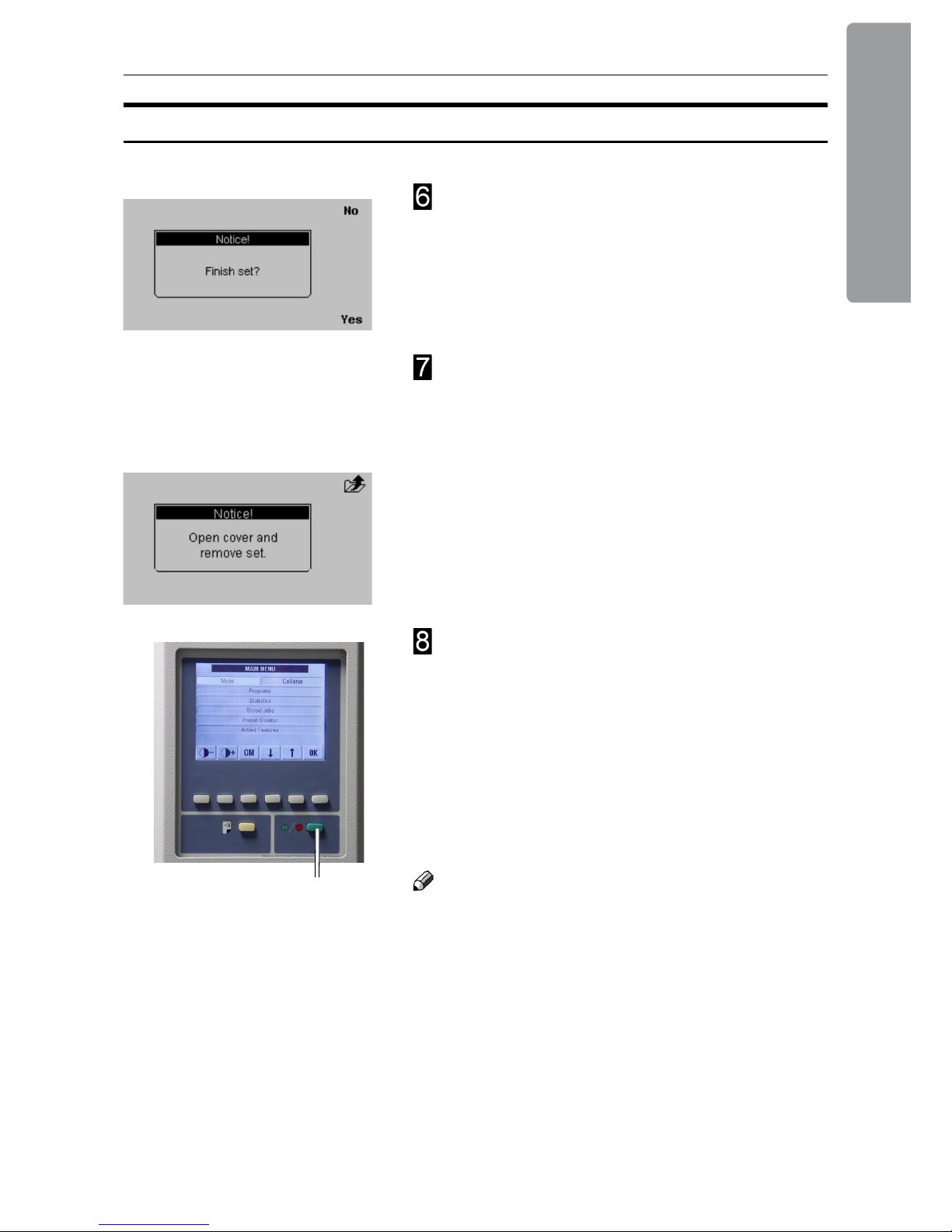
Close the Booklet Maker top cover. The message
“Finish set?” will be shown in the control panel.
There are now two choices:
Press the “Yes” button on the Booklet Maker.
The set will be nished and fed to the belt
stacker.
or
Press the “No” button on the Booklet Maker.
The message “Open cover and remove set”
will be shown in the Booklet Maker control
panel. Open the Booklet Maker top cover and
remove the set. Close the top cover.
Press the green button (B) on the Feeder/Collator
to start making booklets.
•
•
Note
In either step, 4 or 6 above, instead of following the
calibration procedure you can:
Press the “Purge” button on the Feeder/Collator.
The set will be nished and fed to the belt stacker.
and/or
Press the green button (B) on the Feeder/Collator
to directly start making booklets.
•
•
B
On-line Mode, continues
2. Making Booklets
32
Make sure Booklet Maker is in stand-by mode, i.e. that a job is not in progress.
Make necessary settings according to “Changing settings” earlier in this section.
The Booklet Maker is now in stand-by mode and will start automatically when a set is
manually fed into the Booklet Maker.
Sets can be fed either to the optional hand feed tray (A) or to the hand feed slot (B) in
the top cover.
Off-line Mode
A
B
Note
The Booklet Maker can be hand fed while it is still docked to a Collator/Feeder. The
Collator/Feeder can be used for internal stacking at the same time as the Booklet Maker is
used for hand feeding.
33
3. Admin
From the Main screen, press the [Admin] button to get to the Admin screen. Here you will
nd additional features and settings.
The Admin Screen
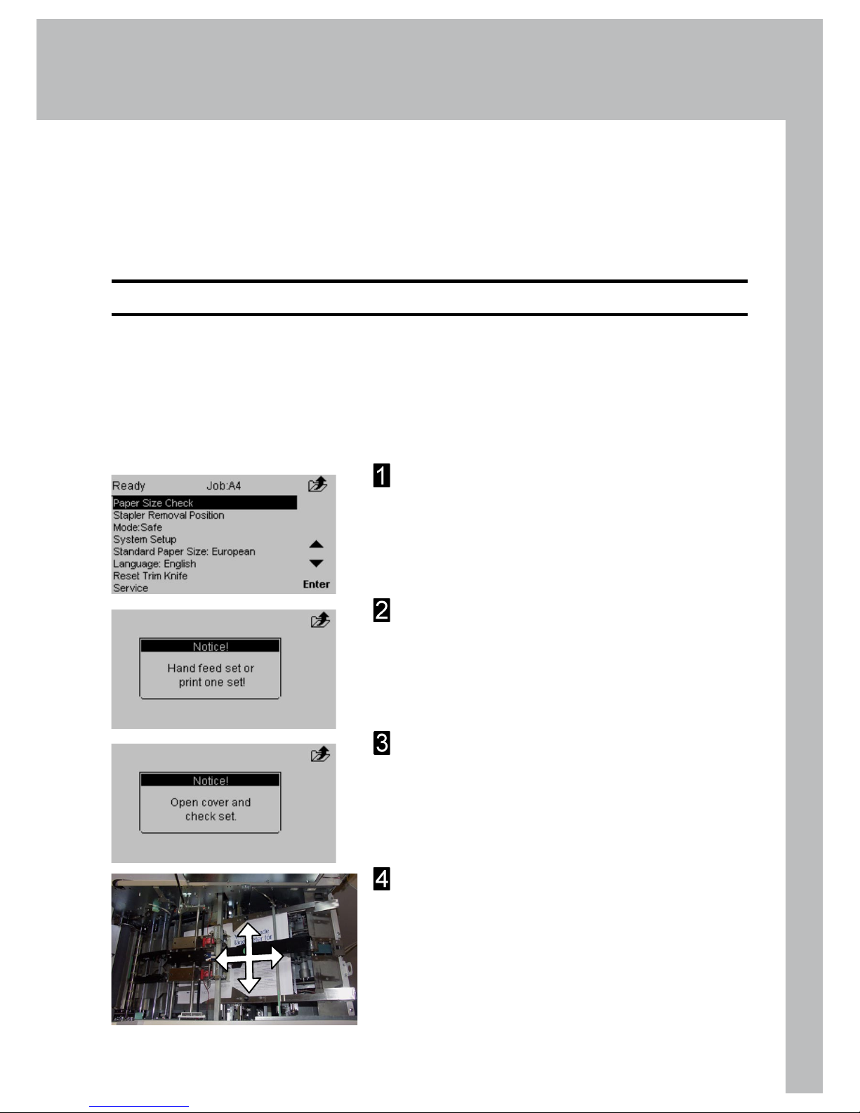
Paper size check
Use [Paper size check] to verify that the Booklet Maker
paper size setup corresponds to the actual hand fed
sheets. If sheets/sets instead are fed from a Feeder/
Collator, this control can be made after a calibration
set has been sent from the Feeder/Collator, see Online mode under section 2.
Select [Paper Size Check] and press the [Enter]
button.
The Message “Hand feed set or print one set!” is
displayed. Hand feed a set to the Booklet Maker.
The message “Open cover and check set!” will
be shown in the Booklet Maker control panel.
Open the Booklet Maker top cover.
Try to move the sheet/set as illustrated to detect
play. If there is play, adjust the paper size setting
in the Booklet Maker accordingly. Perform Paper
size check again and verify that there is no play.
Continue on next page
3. Admin
34
Mode, Safe / Fast
Select desired mode and press the [Enter] button.
Note
If the Feeder/Collator is set to collating and trimming
is set to on, Fast mode will not increase speed.
Instead select Safe mode to ensure highest booklet
quality.
The Booklet Maker can be set in two different modes,
Safe or Fast. The Safe mode is optimized for highest
booklet quality and the Fast mode is optimized for
highest speed. Select [Mode] and press the [Enter]
button.
Paper size check, continues
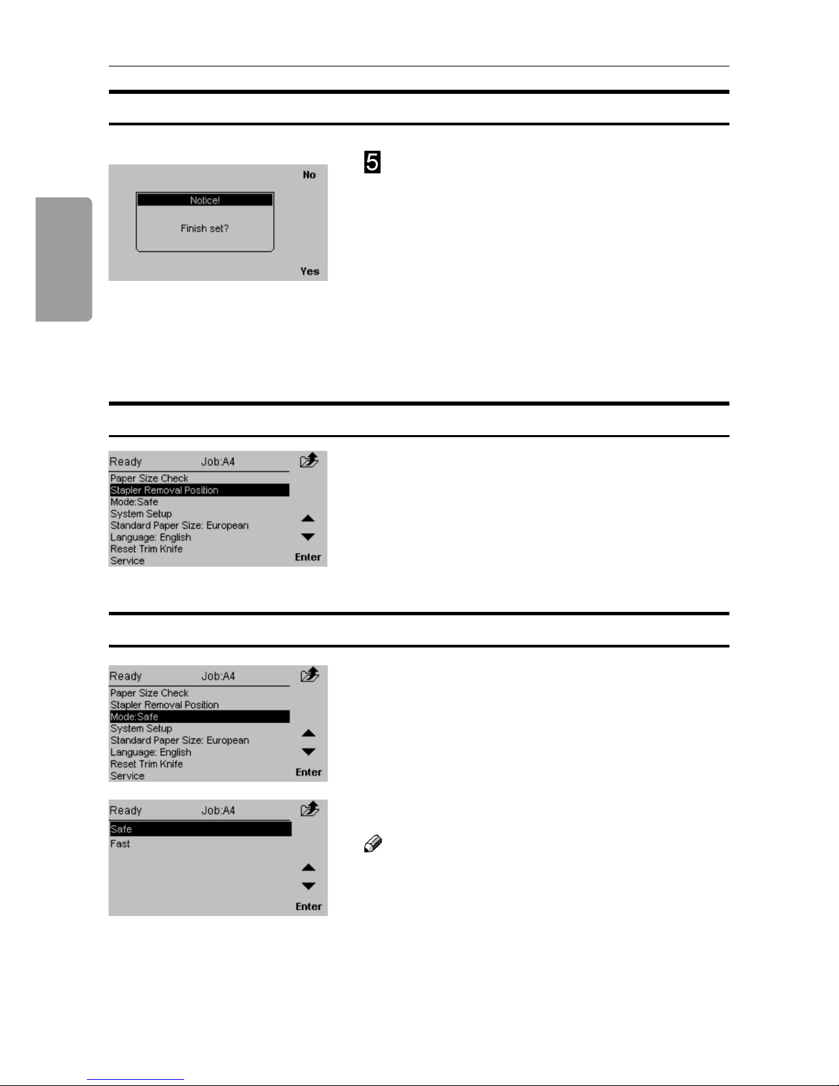
Close the Booklet Maker top cover. The message
“Finish set?” will be displayed.
There are now two choices:
Press the [Yes] button on the Booklet Maker. The
set will be nished and fed to the belt stacker.
or
Press the [No] button on the Booklet Maker.
The message “Open cover and remove set”
will be shown in the Booklet Maker control
panel. Open the Booklet Maker top cover and
remove the set. Close the top cover.
•
•
Stapler removal position
From this screen you can change the position of the
stapler drive bar. This will facilitate the removal and
inserting of the staple cartridge.
Select [Stapler removal position] and press the
[Enter] button.
35
3. Admin
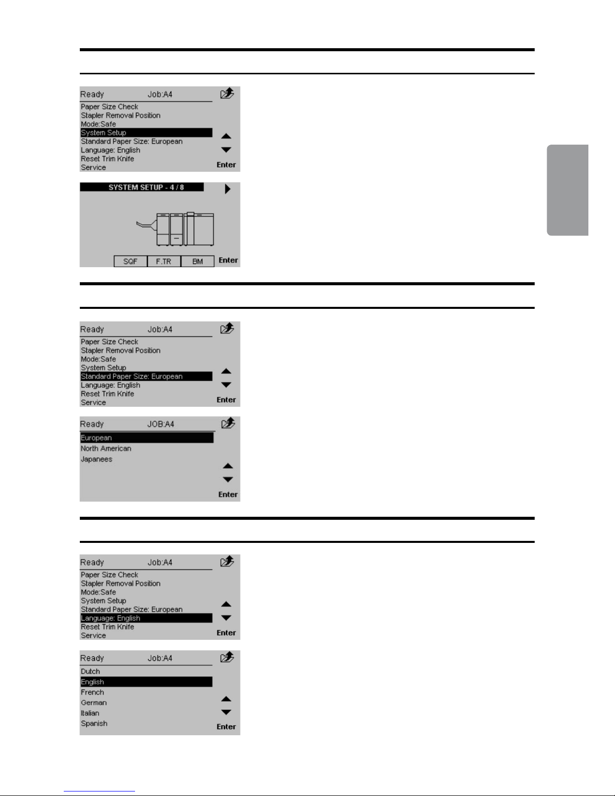
Standard Paper Size
By changing the paper size standard, the preset
paper sizes are altered to best t your regional
standard. Also, the units will change between
millimetres and inches accordingly. Select [Standard
Paper Size] and press the [Enter] button.
Select the desired standard and then press the
[Enter] button.
System Setup
Scroll to the right system conguration and press the
[Enter] button.
[System Setup] allows you to change how the
booklet making system setup will appear in the
control panel. Select System Setup and press the
[Enter] button.
Language
From this screen you can change the language in
the user interface. Select [Language] and press the
[Enter] button.
Select desired language with the [arrow] buttons and
press the [Enter] button.
3. Admin
36
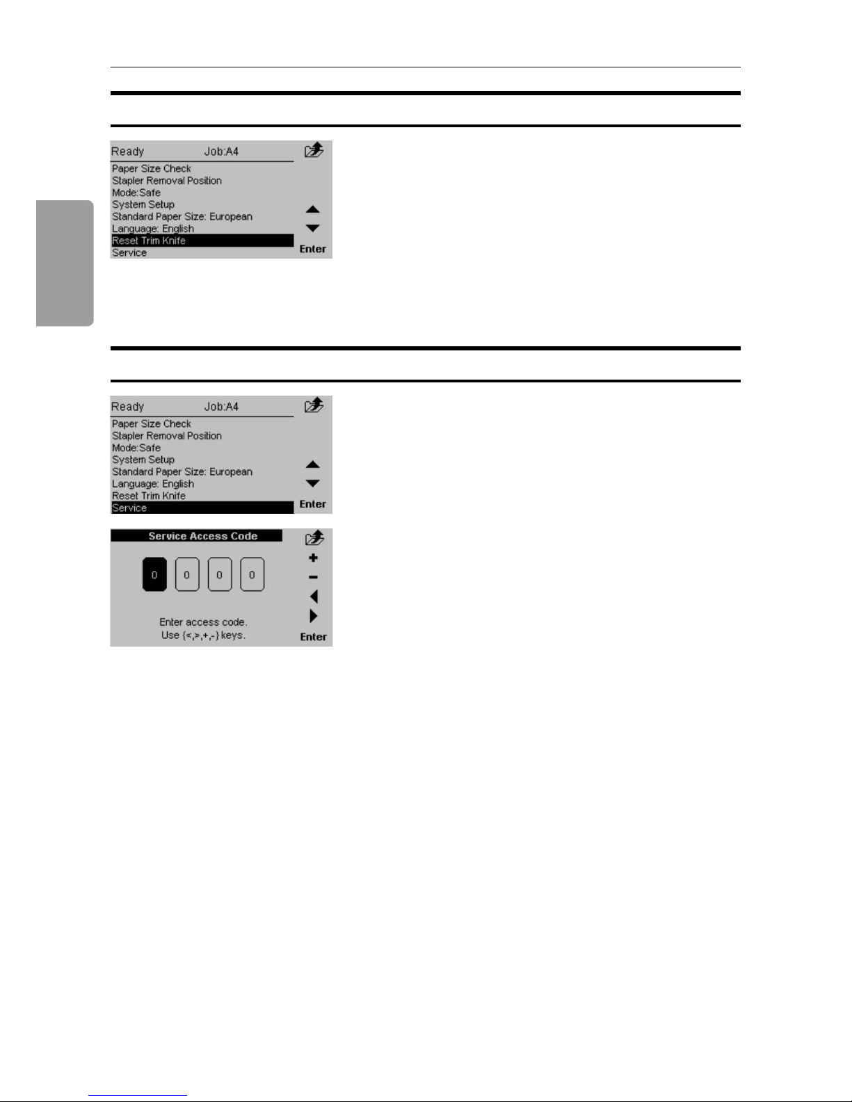
Reset Trim Knife
From this screen you can reset the position of the
trimknife. This is useful when the knife is stuck in the
active/down position. You will get fault codes TR 201202 or BM 210-211.
Select [Reset trim knife] and press the [Enter] button.
Service
This screen to access service is for authorized
service personnel only and is password protected.
37
4. Jobs
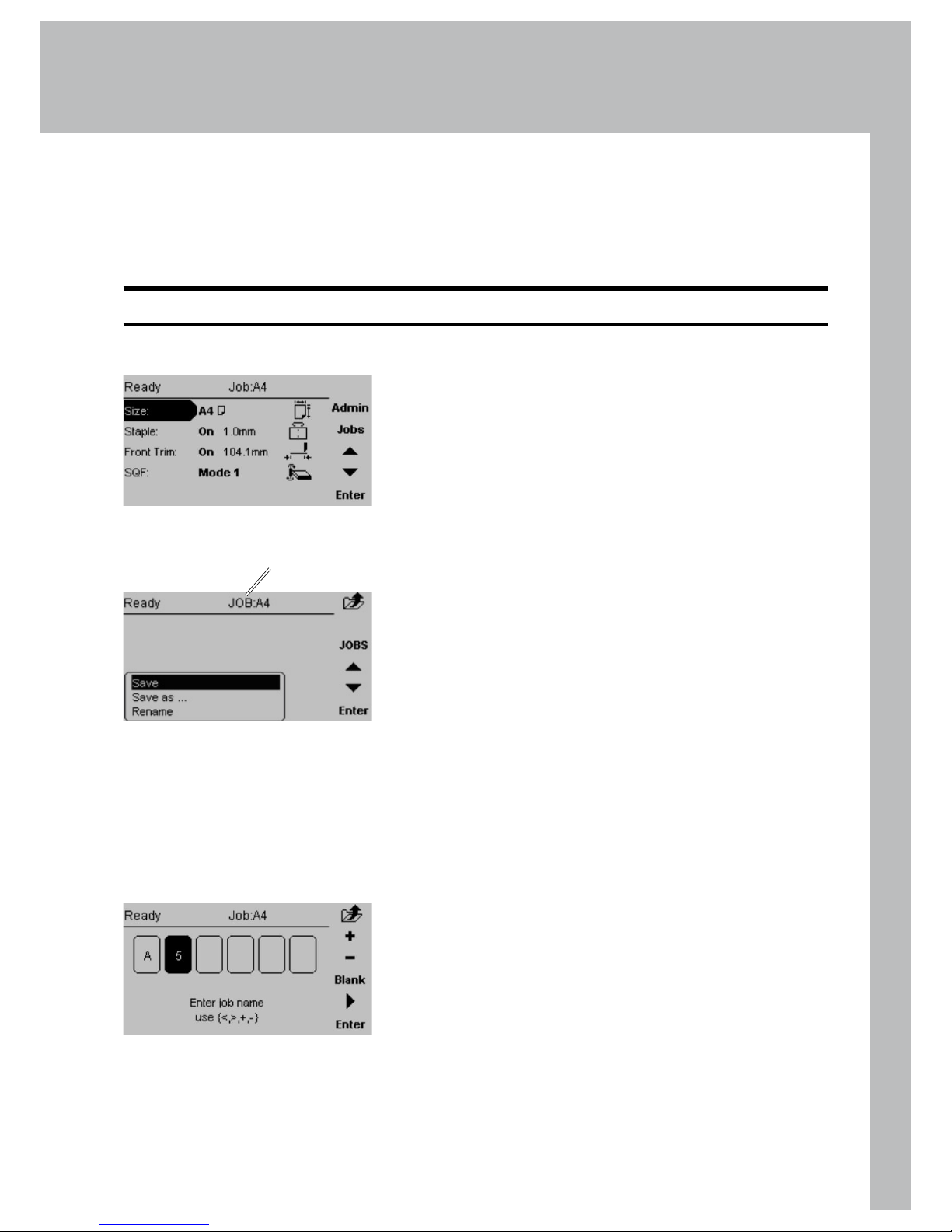
Storing and Deleting Jobs
Now you have three choices:
Choosing [Save] will overwrite the current Job.
The Current Job name is displayed on top of the
screen.
Choosing [Save as...] gives you the option to
save it as a new job or overwriting another job.
Choosing [Rename] will overwrite the Current Job
(if changes were made). This is the same as the
Save option, but now you have the possibility to
enter or change the name for the current job.
•
•
•
The Booklet Maker has a maximum storage capacity of 10 different jobs. Also see section 2
Making Booklets.
Storing a Job
Change all settings according to section 2 for a
particular job.
Now the changes are just temporary. You can run
the system with these changes but as soon as you
change something again the previous settings will be
lost.
To store the settings, press [Jobs] from the Main
screen.
Current Job
This screen is displayed if Rename is Entered from
the Jobs screen.
Press [+] or [-] to change highlighted character. Press
[Blank] for no character. Move the cursor by pressing
the [Arrow]. Press [Enter] when done.

4. Jobs
38
Recalling a Job
To recall a stored job press the [Jobs] button from the
Main screen.
Then press the [Jobs] button from the Jobs screen.
Select one of the previously stored jobs from the list.
Press the [Enter] button to recall the job. This Job is
now uploaded and becomes the current job.

39
5. Clearing a Paper Jam
Clearing a Paper Jam
If an error such as a paper jam condition should occur, it is indicated in the control panel
on the Booklet Maker. The nature of the fault is generally displayed in clear text at the top.
In the centre of the display the diagram shows in which module and where the error has
occurred. At the bottom of the display an error code is displayed and a text explaining the
error. See examples below.
General
Jams in the Booklet Maker are indicated by a square
shaped ashing symbols in the control panel.
If one of the top covers is open, the symbol on the
control panel shows the top cover ashing.
Flashing symbol
Top cover highlighted
and ashing

5. Clearing a Paper Jam
40
To clear a paper jam in the infeed or staple area
Open the top cover.
Remove jammed sheets.
Close the top cover.
To clear a jam indicated in the folding area
Open the top cover.
Close top cover.
If the jam still remains:
Switch off the Power.
Switch on the Power.
Continue on next page
Clearing a Paper Jam
Booklet Maker
Inside the Booklet Maker
Folding area Stapling area

41
5. Clearing a Paper Jam
If the jam still remains:
Switch off the Power
Set the fold adjust levers (A) on both sides to “8” to separate the fold rollers.
Lift up the guide (B) from below the upper fold roller (C).
Use the key (D) from the tool box and crank the upper fold roller to remove jammed
sheets.
If a Trimmer is installed, removing the Trim Bin gives you access to the fold stop area
from the outfeed side of the Booklet Maker.
Put the key back in the tool box.
Replace the Trim Bin, if the Trim Bin was removed.
Switch on the power.
Inside the Booklet Maker, continues
CD B
A
Booklet Maker,
top view

5. Clearing a Paper Jam
42
Trimmer
Clearing a Paper Jam
Lift up the infeed roller shaft (A).
Secure under latch (B)
Remove the jammed sheets in the infeed area.
After the jammed sheets are removed, lift up the latch (B) and place the infeed roller
shaft in the operating position.
Clearing Jam in Input Area
The upper trimmer blade on the trimmer is protected by a knife protection plate that moves
away during the cutting stroke. Jams can occur in the input area or the exit area.
WARNING:
Never put ngers or other parts of the body between the upper and lower trimmer knives.
B
A
Infeed roller shaft,
operating position
Infeed roller shaft,
lifted position

43
5. Clearing a Paper Jam
Lift the exit compression brackets (A).
Secure them under the latch (B).
Remove the jammed sheets from the exit area.
After the jammed sheets are removed, lift up the latch (B) and place the
compression brackets in the operating position.
Clearing a Paper Jam, continued
B
A
Clearing Jam in Exit Area
B
Compression brackets,
operating position
Compression brackets,
lifted position

5. Clearing a Paper Jam
44
Open the top cover.
Lift up both upper feed belts (A).
Note
Press the green-labelled latches (B) to release.
Remove the jams.
Place the upper feed belts in normal position.
Close the top cover.
Inside the SquareFolder
Exit Area
Open the top cover (A).
Lift up the Belt Stacker Cover (B).
Remove the jam.
Place the Belt Stacker Cover in normal position.
Close the top cover.
A
A
Clearing a Paper Jam
SquareFolder
B
B

45
6. Troubleshooting
Fault codes
When there is a jam or fault condition in the Booklet Maker system, a fault code and a
short description will be displayed in the control panel on the Booklet Maker.
Some faults can be rectied by the operator and some faults only by an authorized
technician.
Fault codes that generally can be rectied by the operator:
Booklet Maker BM-201 to BM-211 indicates “Clear area”
BM-212 Indicates “Remove Stacked Sheets”
BM-213 Indicates “Too Many Sheets”
BM-401 indicates “Check Staples”
Trimmer TR-201 to TR-204 indicates “Clear area”
TR-205 indicates “Close trimmer belts”
TR-501 indicates “Waste bin full”
SquareFolder SQF-201 to SQF-206 indicates “Clear area”
How to clear a paper jam when the message “Clear area” is shown is described in section
5. Actions to solve the remaining fault codes are described on the next page.
Note
If procedures specically described in this manual do not rectify the problem:
Open covers and verify that everything appears to be in a normal state. Close covers.
Switch off the power and wait 10 seconds before power is switched on again.
Call for an authorized technician.
•
•
•
General

6. Troubleshooting
46
Booklet Maker Fault Codes
Trimmer Fault Codes
Waste Bin Full
This message will be displayed when the trim bin is full or when a trim strip is prevented
from falling down into the trim bin. Empty the trim bin and remove loose trim strips from
inside the Trimmer. See section 1 Basics for how to remove the trim bin.
Check Staples
This message will be displayed when a staple cartridge is empty or when stapling could
not be performed. Check in the following order:
If a staple cartridge is empty, replace according to section 1 Basics.
If staple cartridges are OK; remove the set and check that the number of sheets is
within specications.
If staple cartridges are OK and the set is within specication, remove and check stapler
head according to section 1 Basics.
Close trimmer belts
This message will be displayed when either of the trimmer belt is in the lifted position. Make
sure that both the infeed roller shaft and the exit compressing brackets are in the operating
position, see section 5, Trimmer, Clearing a Paper Jam.
Too many sheets
This message will be displayed when the set fed to the Booklet Maker is outside
specications. Open the top cover, remove the set and close the top cover.
Remove stacked sheets
This message will be displayed if there is a miss-feed or double-feed in the Feeder/Collator
when the set is delivered to the Booklet Maker.
Either:
Open the top cover, remove the set and close the top cover.
or
Press the “Purge” button on the Feeder/Collator. The set will be fed to the belt stacker.
and/or
Press the green button on the Feeder/Collator to directly start making booklets.
•
•
•

47
6. Troubleshooting
If booklet quality is inconsistent, rst make sure the actual paper size is matching the
paper size set on the control panel. Perform a Paper size check, see section 3.
If booklet quality is consistently poor such as staples not aligned with the fold or
staple and fold line do not match the print, see Staple and Fold Alignment under
section 2.
If the folding action is poor of if the cover of the booklet tends to be torn from the set,
see Fold Quality below.
If feed errors occur or if the booklets are not square folded properly, especially
regarding heavier booklets, see SquareFolding Quality below.
•
•
•
•
Fold Quality
If the adjustments from the control panel result in inconsistencies or inaccuracies it could
be due to paper quality and/or set size. For those cases it is possible to change the ball
conguration in the ball cages in the pre-fold transport. The purpose is to apply adequate
pressure on the set to ensure proper alignment against the fold stop before the set is folded.
The default conguration for BM 2000 is with glass balls closest to the outfeed and plastic
balls closest to the infeed. Additional replacement steel, glass and plastic balls are located in
the tool box above the fold section.
Example:
If booklets comes out with the staples on the back of the booklet, the
conguration is to heavy. The set was allowed to buckle (travel) to far before
it was folded.
If booklets comes out with the staples on the front of the booklet and/or if the
fold is skew, the conguration is to light. The set did not travel all the way
down to the fold stop and was not aligned correctly before it was folded.
See table below for ball conguration guidelines.
•
•
Ball conguration guidelines 1 2 3
Single large sheets, in fold only mode,
with low paper weight/stiffness
Plastic - -
Small quantity of sheets, with low
paper weight/stiffness
Plastic - Plastic
Default conguration Glass - Plastic
Large quantity of sheets Glass - Glass
Large quantity of sheets, with higher
paper weight/stiffness
Steel - Glass
If markings occur on the centre fold when
running larger quantities of sheets
Glass Plastic Plastic
1 2 3
1 2 3
Booklet quality
Note
The table above is meant purely to be a guide. Other congurations might work better
depending on the characteristics of the paper quality in conjunction with the set size.
6. Troubleshooting
48
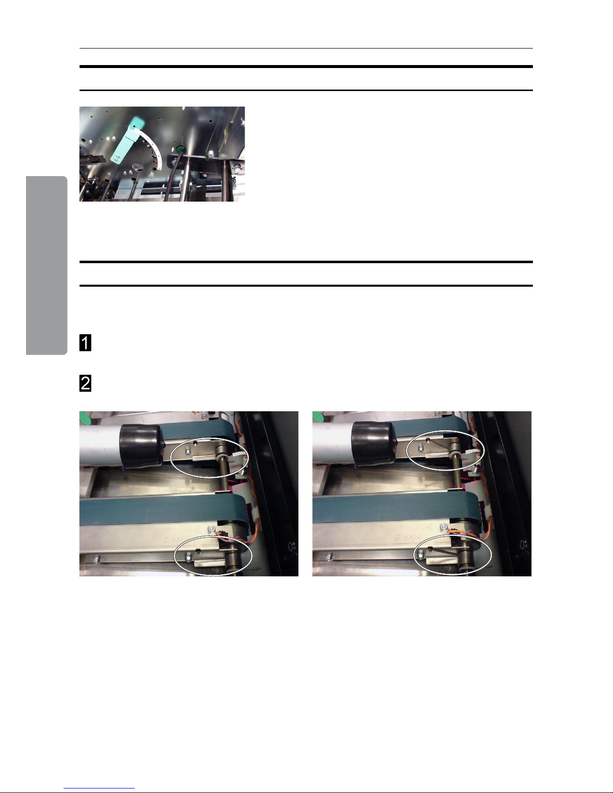
If feed errors occur or if the booklets are not square folded properly, especially regarding
heavier booklets, follow this procedure:
Make sure that the clamps and feed belts are clean. See cleaning instructions under
section 7.
Place both springs in the upper position.
SquareFolding Quality
Under extreme circumstances, when the cover
sheet tends to be torn from the rest of the set, this
can be rectied by adjusting the Fold Adjust Levers
located above the pre-fold transport. There are eight
positions for each lever. The topmost notch is the
default position. Move the lever notch by notch until
performance is satisfactory.
Fold Quality, continues
Springs in normal position. Springs in upper position.

49
7. General Remarks
Do’s And Don’ts
Always follow all warnings marked on, or supplied with, the equipment.
Always exercise care in moving or relocating the equipment.
Caution
Unplug the power cord from the wall outlet and machine before you move or relocate the
equipment.
Do not remove the covers or guards that are fastened with screws.
Do not override or bypass electrical or mechanical interlock devices.
Do not operate the equipment if you notice unusual noises or odours. Disconnect the
power cord from the power source and call your authorized technician to correct the
problem.
Warning
This is a Class A product. In a domestic environment this product may cause radio
interference in which case the user may be required to take adequate measures.
Note
The domestic environment is an environment where the use of broadcast radio and
television receivers may be expected within a distance of 10 m of the apparatus
concerned.
Do not put ngers or other parts of the body between the upper and lower trimmer
knives.
Do not switch off the power while the machine is running. Make sure the machine cycle
has ended.
Do not open covers while the machine is running.
Do not move machine while the machine is running.
Do not make arbitrary changes to the machine
•
•
•
•
•
•
•
•
•
•

7. General Remarks
50
Placing Your Machine
Machine Environment
Power Connection
• Always connect the equipment to a properly grounded power source. If in
doubt, have the power source checked by a qualied electrician.
Warning
Improper grounding of the equipment can result in electrical shock.
• Never connect the machine to a power source that lacks a ground connection
terminal.
• Always locate the equipment on a solid support surface with adequate strength for the
weight of the machine.
• Always keep magnets and all devices with strong magnetic elds away from the
machine.
If the place of installation is air-conditioned or heated, do not place the machine where it
will be:
• Subjected to sudden temperature changes.
• Directly exposed to cool air from an air-conditioner.
• Directly exposed to heat from a heater.
51
7. General Remarks
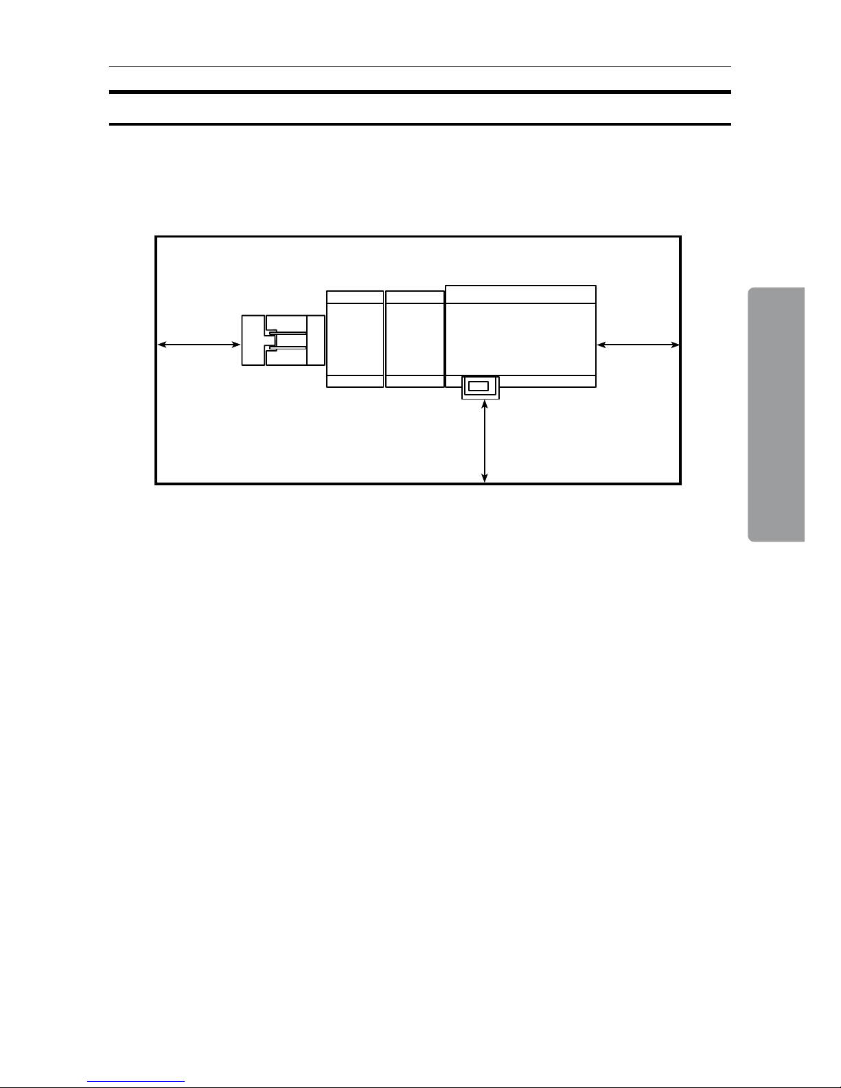
Access to Machine
Place the machine near the power source, providing clearance as shown.
1. Left: more than 400 mm / 15 3/4”
2. Front: more than 555 mm / 21 7/8”
(3). Right: more than 400 mm / 15 3/4” (for stand alone installation only)
2
(3)
1
7. General Remarks
52
Maintaining Your Machines
Caution
Never attempt any maintenance function that is not specically described in this
documentation.
Lubricating Staplers and Clinchers
Booklet Maker
The parts that need lubrication are shown in the table below.
Drive post Stapler drive bar Stapler lift bracket
Staple driverClincher
PART FREQUENCY PART LOCATION
Clinchers Every 20,000 booklets Beneath the stapler head assembly (thin oil)
Drive posts Every 20,000 booklets Staple cartridge (grease)
Stapler drive bar Every 20,000 booklets Above the stapler head (grease)
Stapler lift bracket Every 20,000 booklets Above the stapler head (grease)
Staple driver Every 20,000 booklets Staple driver (thin oil)
53
7. General Remarks
Cleaning Feed Belts
SquareFolder
The feed belts need to be cleaned regularly when in use, and if the unit has not been used for
a period of time. How often this should be done, depends on the paper type and print quality.
An increasing number of jams is one indication of the need to clean the feed belts. Clean
the feed belts with water and a lint free cloth.
Open the top cover.
Clean the upper feed belts (A). The upper feed belts can easily be rotated in either
direction.
Lift up the upper feed belts to access the lower feed belts.
Clean the lower feed belts (B). Rotate the lower feed belts towards the outfeed side for
complete cleaning.
Place the upper feed belts in normal position.
Close the top cover.
Upper feed belts raised
B
A
Upper feed belts in normal position
7. General Remarks
54
Cleaning Square Folding Clamps
A
Remove any residue from upper and lower clamps (A), which is the area clamping the
booklet. Pay special attention to the right angled corners of the clamp proles.

55
8. Specications
Machine Specications
Booklet Maker BM 2000
Specications Remarks
Maximum Speed 3000 booklets / hour (A4 / 8.5x11” sheets)
Paper Size, minimum
(booklet making)
Width 120 mm / 4 3/4”
Length 210 mm / 8 1/4”
Paper Size, maximum
(booklet making)
Width 320 mm / 12 5/8”
Length 470 mm / 18 1/2”
Paper Length, minimum
(edge & corner stapling)
111 mm / 4 3/8”
Paper Length, maximum
(edge & corner stapling)
240 mm / 9 7/16”
Paper Weight (Minimum) 60 gsm/16 lb. Bond
Paper Weight (Maximum) 300 gsm / 172 lb. Index / 115 lb. Cover
Input / Output Sheets 1 – 25 Sheets (80 gsm / 20 lb. Bond,
equivalent)
Stapled
Input / Output Sheets 1 – 2 Sheets Folding only
Hand feeding Possible
Weight 161 kg / 354 lb. Including Stacker
Dimensions (L x H x D) 1520 x 1135 x 680 mm / 60” x 45” x 27” Including Base and Stacker
Power Source 100 / 110 / 115 / 127 / 220 / 230 VAC
50-60 Hz
+ - 10%
Power consumption 25 W (15 W BM 2000, 10 W SQF 2000) Stand by
0.1 - 1 kW
Maximum 1 kW
Continuous Operation for BM
2000+FTR 2000+SQF 2000
Safety class Class 1 BM 2000+FTR 2000+SQF 2000
Protection class IP X0 BM 2000+FTR 2000+SQF 2000

8. Specications
56
Trimmer FTR 2000 (option)
Specications Remarks
Maximum Speed 2000 booklets / hour (A4 / 8.5x11” sheets)
Minimum input sheet
length for trimming
250 mm / 9.84” 125 mm / 4.92” booklet when
folded to a booklet
Minimum trimming *4 mm / 0.16”
Maximum trimming 16 mm / 0.63”
Minimum length, trimmed
booklet
120 mm / 4.72”
Maximum length,
trimmed booklet
220 mm / 8.66”
Paper Weight (Minimum) Same as BM 2000
Paper Weight (Maximum) Same as BM 2000
Input / Output Sheets Same as BM 2000
Input / Output Sheets Same as BM 2000
Hand-feeding Possible (Together with Booklet Maker)
Weight 83 kg / 183 lb.
Dimensions (L x H x D) 350 x 1100 x 595 mm / 14 x 43 x 23”
Power Source From BM 2000
* Maximum width of the nished, trimmed booklet is 220 mm (8”5/8). This means, when trimming SRA3
(450 mm) booklets, the minimum trim is 5 mm. When trimming 18” booklets, the minimum trim is 9 mm.
SquareFolder SQF 2000 (option)
Specications Remarks
Speed 1800 booklets / hour (A4 / 8.5x11” sheets)
Paper Weight (Minimum) Same as BM 2000
Paper Weight (Maximum) Same as BM 2000
Input / Output Sheets Same as BM 2000
Input / Output Sheets Same as BM 2000
Hand-feeding Possible (Together with Booklet Maker &
Trimmer)
Weight 60 kg / 132 lb.
Dimensions 350 x 1100 x 595 mm / 14 x 43 x 23”
Power Source From BM 2000

Page intentionally blank

 Loading...