

Morgan MWF-NB165RT User Manual
E-mail: electrical.appliance@dksh.com
www.morgan.my
Market Expansion
Services by
www.dksh.com.my
facebook.com/morganappliances
USER MANUAL
3 Speed
Remote-Control
Wall Fan
MWF-NB165RT
USING THE REMOTE CONTROL CORRECTLY
ACCESSORIES
•
Point the remote controller at the receptor on the base of fan stand and press the
d
esired button.
•
The remote control will work at a distance of up to about six meters and at an angle
o
f 60 degree from right or left of the receptor.
•
The batteries must be removed from the remote controller before it is scrapped to
e
nsure they are disposed of safely.
A
RULES FOR SAFE OPERATION
1. Never i nsert fingers, pencils or any other objects through the grille when fan is in operation.
2. Disconnect the fan when moving from one location to another.
3. Disconnect the fan when removing grilles for cleaning.
4. Ensure fan is placed on a stable surface when operating to avoid overturning.
5. DO NOT expose the fan to rain, water or other liquids, as it may damage the motor and pose a safety hazard.
OVERHEAT PROTECTION OF THE MOTOR
The motor has a built-in thermal-fuse that cuts off the power supply if it is overheated. This prevents the plastic parts
of the fan from damage and deformation due to the high temperatures caused by an overheated motor.
CLEANING
• Be sure to unplug from the electrical supply before cleaning.
• Plastic parts should be cleaned with mild soap and a damp cloth or sponge. Thoroughly remove soap film with
clean water.
• To disassemble each part, reverse the assembly order.
CAUTION:
If the power cord is damaged, it is strongly recommended to have it serviced an authorized service agent.
Receptor
R
emote
Controller
B
C
A. Remote Control (1)
B. Mounting (1)
C. Screw (3)
2 3
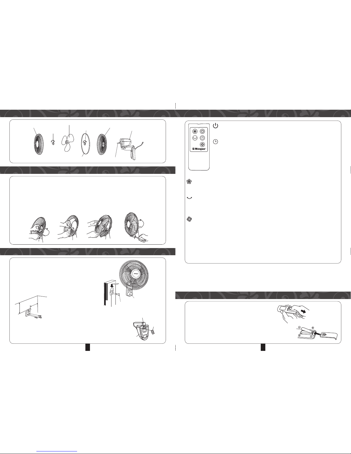
REMOTE CONTROLLER OPERATION
INSERT THE BATTERIES (not included)
ON / OFF BUTTON
• This key is for switching on the fan. The fan will automatically operate at medium speed to
s
peed up the rotation. After 2 seconds it will automatically switch to low speed.
T
IMER BUTTON
•
When this key is pressed repeatedly or continuously, the set operation time wi ll increase by
0.5 hour and up to maximum 7.5 hours in 15 intervals.
•
For instance, if you wish to set the operation duration for is 5.5 hours, this key must be
pressed repeatedly so that the pilot lamps for 0.5 1 and 4 hours are illuminated. This means
that the set time is 0.5 + 1 + 4 = 5.5 hours.
• The timer setting indicated by the pilot lamp will decrease gradually by an interval of 0.5 hours.
• Do not press the TIMER key when you prefer continuous operation (all pilot lamps will not illuminate)
SPEED BUTTON
• After the fan has started, this key serves as a speed selector in the sequence from
LOW–MEDIUM–HIGH–LOW–MEDIUM when this key being pressed repeatedly or continuously.
OSCILLATION BUTTON
• This key starts or stops the fan oscillation. To select direction, press this key until the fan moves to the desired
direction and then release the key.
Important note: Do not try to change the fan direction forcibly by hand; otherwise the fan will be damaged.
WIND MODE BUTTON (applies only for remote control)
• This key is a selector for wind mode. The wind mode changes from
NORMAL–NATURAL–SLEEP–NORMAL–NATURAL wind when this key is pressed.
The features of 2 wind modes are as follows:
NORMAL WIND: The fan delivers air constantly with high, medium or low speed set by the SPEED button.
NATURAL WIND: The fan delivers air according to the program preset in advance and simulating natural wind. The
wind varies from strong to gentle and vice-versa for a natural feel.
SLEEP WIND: The wind varies from strong to gentle.
1. Press dow n on the battery compartment cover and slide it out.
2. Insert two batteries, making sure that the positive terminals
are facing the proper way.
3. Replace the cover.
NOTES : Use only “AAA” manganese or alkaline batteries.
PARTS IDENTIFICATION
BLADE AND GRILLE ASSEMBLY
Front Grille
Spinner
Blade
Plastic Nut
Rear Grille
Motor
Motor Shaft
Circlip
STEP 1: Unscrew the spinner clockwise and the nut counter clockwise to remove both blade and grille.
STEP 2: Position the rear grille with handle facing upwards.
STEP 3: Screw on plastic nut tightly to attach rear grille.
STEP 4: Install the blade onto the shaft until it reaches the retaining pin.
STEP 5: Screw spinner onto motor shaft counter clockwise
STEP 6: Press the rim of the front grille onto the rear guard until the front guard is fitted tightly.
STEP 7: Secure both grilles firmly by tightening the fan Grille’s clip
STEP 1-3 STEP 4-5 STEP 6 STEP 7
INSTALLATION
The fan should be installed on a solid wooden or pillar which
stands vertically to the floor.
Caution: To prevent the fan from falling off, do not install it on
walls less then 10cm thick or made of materials that are easily
damaged.
1. INSTALLING THE MOUNTING BRACKET
Fix the supplied mounting bracket firmly onto the wall using the
two supplied screws.
NOTE: The bracket should be
positioned at least 35cm from the
ceiling and at least 30cm from
adjoining wall.
2. INSTALLING THE STAND
Mount the stand on the bracket by inserting the bracket catch
into the slot on the stand.
30cm
35cm
Ceiling
Wall
Screw
Mounting
Bracket
Stand
Slot on rear side
Mounting
bracket
Stand
 Loading...