

Page 1
Salamander
Ceramic Infrared Emitters
Technical Manual
Mor Electric Heating Assoc., Inc.
5880 Alpine A ve. NW, Comstock Park, MI 49321, USA
Tel: 616-784-1121, 800-442-2581, Fax: 616-784-7775
E-Mail: sales@infraredheaters.com
1
Page 2

Table of Contents
Introduction.............................................................................................................
Agency Approvals....................................................................................................
Comparing Different Forms of Infrared Heat......................................................
Radiant Emission Patterns of Ceramic Emitters...................................................
Ceramic Infrared Panel Design..............................................................................
Infrared Heating Basics..........................................................................................
Infrared Energy ........................................................................................................................
Emissivity................................................................................................................................
Electromagnetic Radiation......................................................................................................
Infrared Spectrum....................................................................................................................
Stefan-Boltzmann Law .............................................................................................................
Planck's Law ...........................................................................................................................
Wien's Law ..............................................................................................................................
Surface T emperature and Radiation Emissions.......................................................................
2
2
3
4
5
6
6
6
7
7
7
8
9
10
Emitter Surface Temperature.................................................................................
Spectral Absorption Curves....................................................................................
Physical Properties of Materials.............................................................................
Reference Data........................................................................................................
Estimating Power Requirements............................................................................
Thermoforming........................................................................................................................
W ater Evaporation...................................................................................................................
11
12
13
14
15
15
18
2
Page 3

Introduction
In focus with our Mission Statement, we constantly strive to maintain a
communication level with our customers. In this revised, second issue of our technical manual, we hope
to educate the public on the technical aspects of ceramic infrared emitters. Devised, not as a selling tool
but an informational source, there comes a time where selling becomes secondary to informing, and by
this process, informing becomes the primary source for selling. It has been proven that what we know
and understand best is what we sell and utilize most. It is in this exchange of information that we hope to
create a better understanding of our product, the benefits it offers, and heighten awareness to its potential
for the future.
Agency Approvals
Salamander ceramic infrared emitters, manufactured by Mor Electric Heating Assoc., Inc.,
have been tested by Underwriters Laboratories of Northbrook, Illinois, USA. Emitters rated up to 240
volt are UR and C-UR recognized to the standard for safety of electric appliances UL-499 and C-22-2
number 72-M-1984 for electric heating elements.
Reference: Project No. 95NK17113A
File No. E-181581
EC Declaration of Conformity
This is to certify that the:
Salamander Ceramic Infrared Emitters Comprising of:
FTE, FFE, HTE, HFE, HSE, L TE, ESE, and Associated Sheet Metal Fixings and Reflectors
Manufactured By:
Mor Electric Heating Assoc., Inc.
5880 Alpine N.W .
Comstock Park, Michigan 49321
USA T el: 1-616-784-8997
Is in Compliance With all Implemented EU Requirements:
EU Directive 89/336/EEC Electromagnetic Compatibility
EU Directive 73/23/EEC Low V oltage Safety
EU Directive 93/68/EEC CE Marking
3
Page 4

Comparing Different Forms of Infrared Heat
Throughout the years many different forms of infrared heat sources have been developed. Some
of the more familiar forms seen today are metal sheathed tubular heaters, quartz tubes, quartz lamps, gasfired catalytic, flat faced panels, and ceramic emitters. Each source has its own distinctive set of
properties:
Metal Sheath Quartz Tube Quartz Lamp Catalytic Flat Faced Panels Ceramic
Radiant
Efficiency 56% 61% 86% 80% 88% 96%
Physical
Strength High Low Very Low High Medium Medium
Heat-Up
Cool Down Slow Fast Very Fast Very Slow Slow Slow
Max. Temp. 1400 ° F 1600 ° F 4000 ° F 800 ° F 1600 ° F 1292 ° F
Color
Sensitivity Low Low High Low Low Low
Radiant Efficiency: The total amount of energy that is emitted from the source as
infrared radiation. The balance of heat energy from the sources
are transferred via convection and conduction.
Physical Strength: The physical strength of each source. A high rating indicates a
very durable source that can withstand physical abuse such as
dropping a wrench on the source.
Heat-Up/Cool Down: The amount of time required for the source to come up to
operating temperature and cool back down to room temperature.
Maximum Temperature: Maximum operating temperature of the source.
Color Sensitivity: Refers to the ability of a typical load to absorb the spectral
radiation emitted from a source based on the color of the load.
The shorter the wavelength emitted from a source the more color
sensitive a load will be to the sources spectral radiation.
4
Page 5
Radiant Emission Patterns of Ceramic Emitters
Concentrated Uniform
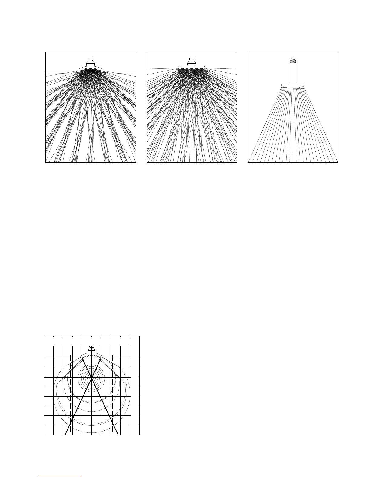
Salamander ceramic emitters are manufactured with three basic emitter faces: concave, flat,
and convex. These emitter face styles will result in the specific radiant emission patterns as shown
above. Note: Infrared radiation is emitted at right angles to the emission surface.
Wide Area
Concentrated: The concave surface will emit a "concentrated" radiant pattern which is highly
effective when zone heating is desired as well as radiant heating in general.
Uniform: The flat surface will produce a "uniform" pattern for even heating at a close
proximity between the emitter and the target being heated.
Wide Area: The convex shape gives off a "wide area" pattern which is desirable in
comfort heating or other applications that require a dispersed radiant emission
pattern.
Salamander Radiant Emission Grid
The Salamander radiant emission grid can be used to
Emitter Spacing
01"2"3"4" 1" 2" 3" 4"
Click to add title
Click to add sub-title
0
1"
2"
3"
4"
5"
6"
7"
determine the proper ceramic emitter spacing when used in an
application such as an infrared panel. In order to achieve an
even heat pattern it is critical that the emitters are spaced so that
their radiant emission patterns overlap when reaching the target.
The more overlap that occurs, the more even the heat will be
across the face of the product being heated. The area of highest
radiant emission intensity for a single emitter is shown within
the two dark crossed lines on the grid. In order for element
emissions to overlap, the dashed line shows an intersection point
at a distance of 7" will occur if the emitters are placed a distance
of 2" apart from edge to edge. This same concept should be used to
Distance From Emitter
either determine the distance to place the product if using an existing
panel, or placement of emitters if building a panel to guarantee
radiant emission overlap.
5
Page 6
Ceramic Infrared Panel Design
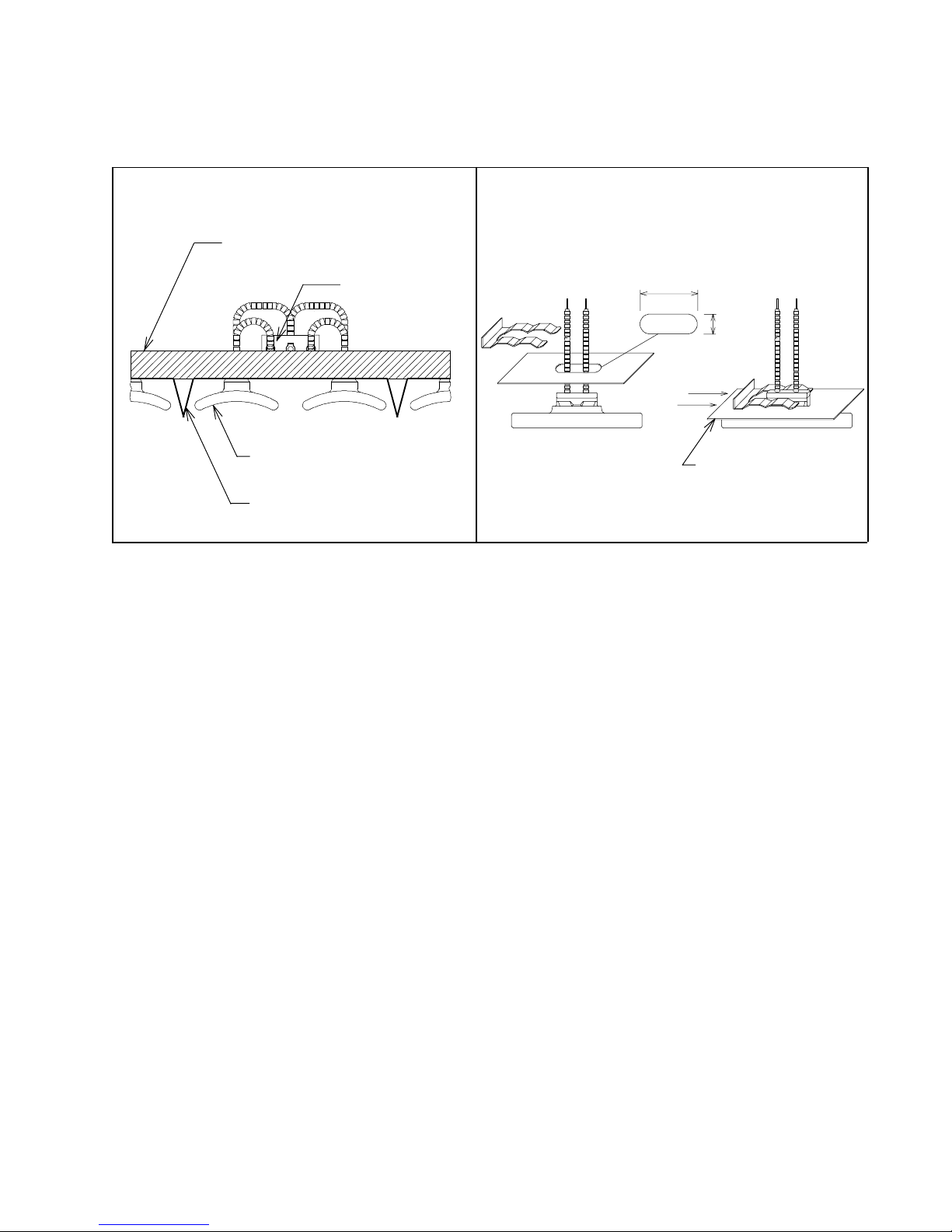
Typical Panel Configuration Ceramic Emitter Mounting
1" Ceramic Fiber Insulation
Click to add title
Ceramic Emitter
Polished Aluminized Steel
or Stainless Steel Reflector,
20 to 24 Gauge
Wiring Specifications:
* High temperature 842 °F (450°C) MG or similar style wire (with a suitable
temperature and amperage rating) should be used for all electrical connections made
within the terminal area of the infrared panel. The high temperature wire must be run
on top of (or above) the ceramic fiber insulation.
3 Pole Ceramic
T erminal Block
1.63"
(41mm)
.59"
(15mm)
Reflector
* Ceramic terminal blocks are recommended to allow for quick emitter replacement,
flexibility in zoning, and "touch safe" design.
* The terminal cover for the infrared panel should be louvered or made out of expanded
metal to minimize the temperature within the terminal area.
Emitter Spacing:
The spacing of the emitters should be such that the resulting infrared emissions incident on the
target will be even and maximized.
* Emitters that are tightly spaced in an array will allow the target to be positioned close
to the emitters and still result in even heating. The intensity and efficiency of the
infrared radiation will be maximized and heat losses will be minimized.
* Emitters that are loosely spaced in an array will force the target to be positioned
further away in order to achieve even heating. This style of panel would typically
result in a lower intensity infrared emission.
6
Page 7

Infrared Heating Basics
This section of the technical manual is a summary of the physics involved in all infrared heating
systems. The information can be used as an aid in calculating system power requirements as well as
determining the feasibility of a given infrared heating application.
Infrared Energy:
When infrared energy strikes an object it may be absorbed, transmitted, or reflected from the
surface. The sum of the amount of energy absorbed, transmitted, and reflected must equal 100% of the
total incident energy. An object is called a "blackbody" if it absorbs (or emits) 100% of incident
infrared radiation.
1 = ρ + α + τ
Where: ρ = reflectivity
α = absorptivity
τ = transmissivity
Example: Infrared energy strikes an object that is 30% reflective, and 20%
transparent, how much infrared energy is absorbed by the object?
1 = .30 + α + .20
α = 1 - .30 -.20 = .50 (or 50% )
The term "blackbody radiation" was derived from an experiment in cavity radiation. A small
hole was drilled into an object and light was focused into the hole. The hole (cavity) appeared to be
black. Light that entered the cavity is trapped and absorbed into the object allowing no light to escape.
Radiant energy emitted from a "blackbody" source is dependent only on the temperature of the cavity
walls and is not at all dependent on any other characteristic of the source such as color .
Emissivity:
A true "blackbody" source for industrial applications has not yet been developed. However,
various radiant heating elements are available with a wide range of radiant efficiencies. The efficiency
of a radiant heater is given by its emissivity value. Emissivity is defined as the ratio of the radiant
energy emitted by an object at a given temperature and the radiant energy emitted by a "blackbody" at the
same temperature.
Where: e = emissivity of source
Ws = Total radiant energy emitted from a source at temperature T
W
= T otal radiant energy emitted from a blackbody at temperature T
bb
e =
W
W
s
bb
1
1
7
Page 8

Electromagnetic Radiation:
Infrared radiation is part of a broad electromagnetic spectrum. The relationship between
electromagnetic radiation is as follows:
c
λ =
f
Where: λ = Wavelength in meters
c = Speed of light ( 3 x 10
8
meters per second )
f = Frequency in hertz ( cycles per second )
Infrared Spectrum:
U.V. Visible Light Near Infrared Far Infrared
Deep Penetration High Low
V B G Y O R For Medical Uses Intensity Intensity
0.4µm 0.7µm 2.8µm 10.0µm
Stefan-Boltzmann Law:
The Stefan-Boltzmann Law gives the total power radiated at a specific temperature from an
infrared source. That is, the entire amount of infrared radiation (at a specific temperature) emitted from
a given source at all associated wavelengths.
R = (e) x (σ) x ( T
4
) Watts/ in
Where: σ = Stefan-Boltzmann Constant
[ 36.58072 x 10
e = Emissivity Value of the Source
T = Surface Temperature of the Source
in K (Kelvin.)
-12
W/ in
2
2 .
°K]
8
Page 9
Planck's Law:
In order to understand the spectral distribution of infrared radiation from a source we must first
understand Planck's Law . Planck's Law gives us the spectral distribution of radiation from a blackbody
source. That is, a source that emits 100% infrared radiation at a given single temperature. It is important
to understand at this point that in practice, infrared sources are made up of thousands of "point sources"
that are all at different temperatures. Each point source will have a different spectral distribution and
the combination of point sources will make up the entire spectral distribution. Therefore, we can only
approximate the spectral distribution using an average surface temperature and emissivity value.
-25
) Watts
- 1 ] in
2 .
µm
R(λ) =
(e) x ( 2.416069 x 10
( λ )
5
[ exp
.014408/λΤ
Where: e = Emissivity of Source
λ = Wavelength in Meters
T = Temperature in K (Kelvin)
K = (°F + 460) / 1.8
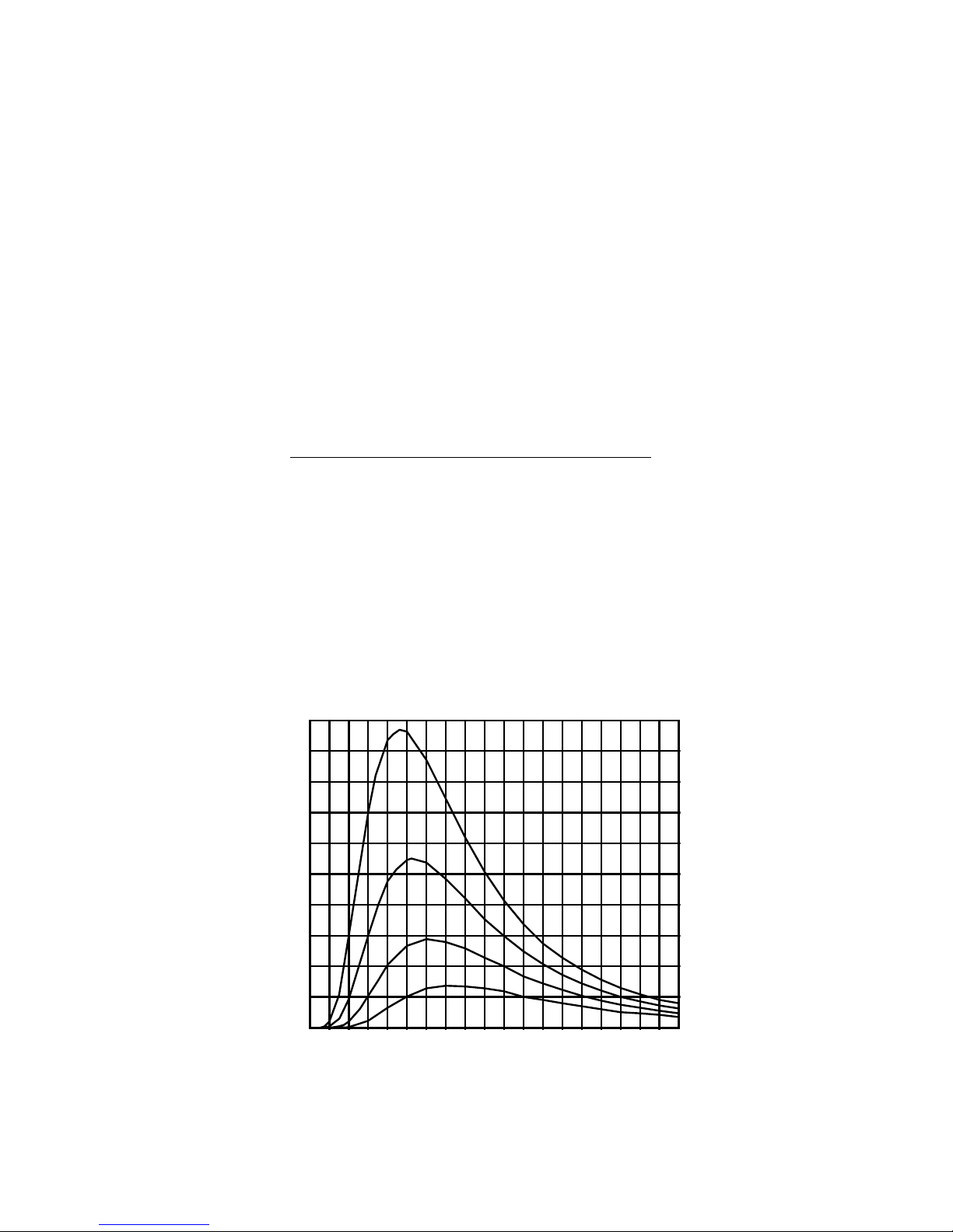
Spectral Distribution of a "Blackbody"
At Various Temperatures
10
D
µm
2 .
9
8
7
6
C
5
4
3
B
2
A
1
Spectral Radiancy, Watts/ in
0
10987654321
Wavelength, Microns (λm)
"A"....800 °F , λm = 4.14 µm "B"....1000 °F, λm = 3.57 µm
"C"....1200 °F, λm = 3.14 µm "D"....1400 °F, λm = 2.81 µm
9
Page 10
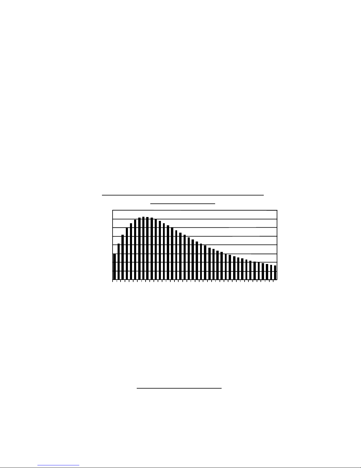
Notice in the Planck's Law curves shown on the previous page that the spectral radiancy of the
source increases proportionally with the source temperature. In other words, the radiant infrared output
from a source increases as the temperature of the source increases. The overall infrared emissions from
a given source is equal to the area under the associated Planck's Law curve. By integrating Planck's Law
at a given temperature with respect to the wavelength we can calculate the amount of infrared emissions
within a given range of wavelengths (See graph below).
Also notice that as the temperature of the source increases, the peak wavelength of the source
becomes shorter. When the temperature of the source becomes too high a noticeable amount of ener gy is
emitted from the source as light. That is, a portion of the energy emitted from the source falls within the
wavelengths associated with light. Referring back to the infrared spectrum chart shown on page 7, visible light
occurs starting at .40µm and ends at .70µm. The infrared spectrum starts at .70µm and extends to 1000µm.
Although the useful range of wavelengths for infrared heating applications occurs between .70µm to 10µm.
% Of Infrared Radiation Emitted From A Blackbody
Between 3 and 10 µm
80%
70%
60%
50%
40%
30%
20%
10%
% Radiation Emitted
0%
100
Wien's Law:
Wien's Law gives the wavelength at which the spectral distribution (given by Planck's Law) of
the radiation emitted by a blackbody is at a maximum point. Note, however, that according to Plank's
Law a range of wavelengths is emitted from a source at a specific temperature! Wien's Law simply
gives the "peak wavelength".
λm =
Where: λm = Peak Wavelength in Meters
400
700
1000
1300
1600
1900
2200
2500
Temperature, °F
2.898 x 10 -3 m K
T
k
T k = Temperature in K (Kelvin)
K = (°F + 460)/1.8
10
2800
3100
3400
3700
4000
Page 11
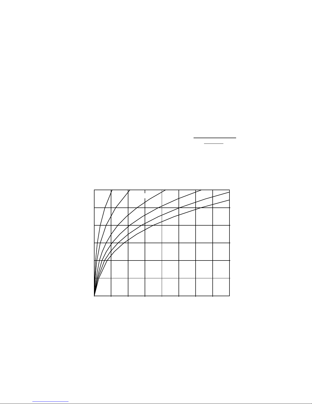
Surface Temperature and Radiation Emissions:
The curve shown below can be used as a quick reference to estimate the amount of infrared
radiant energy emitted from a given source. The curves were derived using the Stefan-Boltzmann Law .
For example, a 1000 °F (538°C or 811 K) infrared source with an emissivity value of .80 (80%) will have an
approximate radiant emission (from the curves below) of 12.5 W att / in2. Using the Stefan-Boltzmann
equation yields the following:
R = ( .80 )( 36.58072 x 10
Surface Temperature vs. Radiation Emission
1200
e=.1
1000
800
600
400
T emperature, °F
-12
)[ (811)4] = 12.65 Watts / in
at Various Emissivity Values
e=.2
e=.4
e=.6
e=.8
2
e=1
200
0
2.5 5.0 7.5 10.0 12.5 15.0 17.5 20
Watts / in
2
11
Page 12
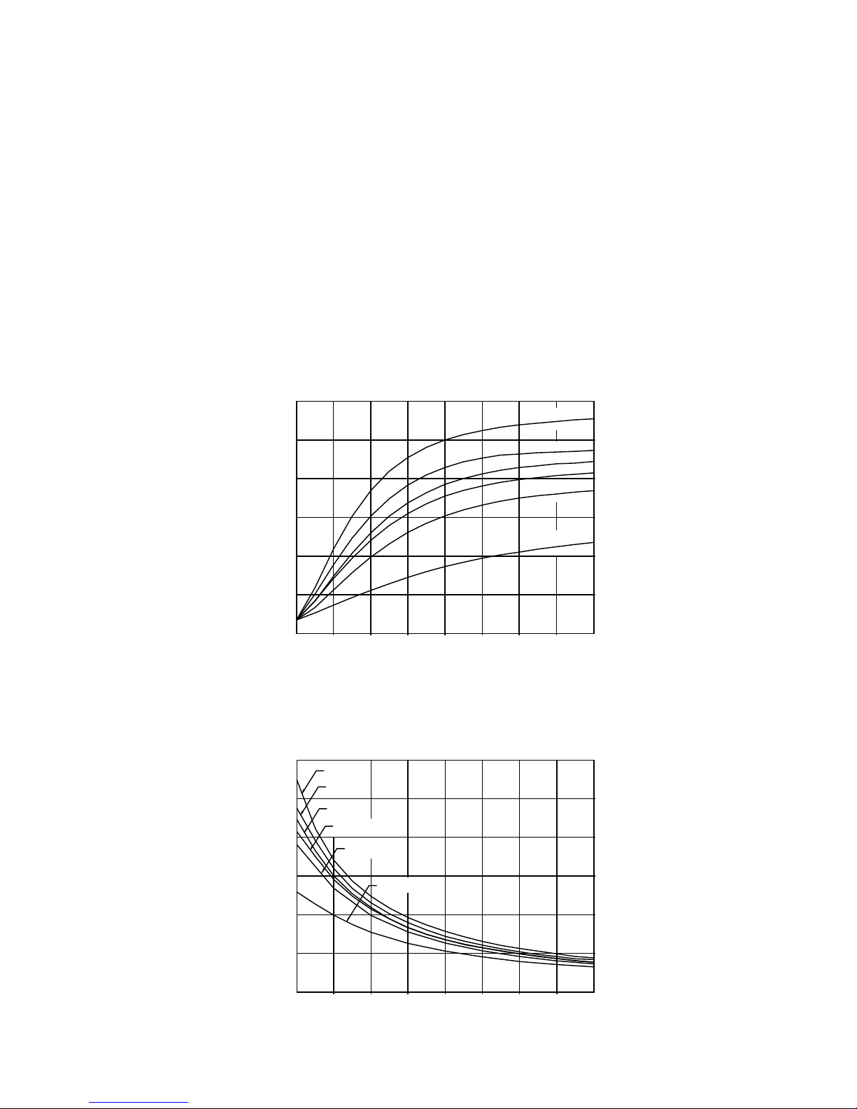
Emitter Surface Temperature
The warm-up and cool-down curves shown below are based on the Salamander FTE style
ceramic emitter. The curves for the Salamander HTE and LTE emitter can be approximated by using the
following factors. If it is desired to know the time/temperature relationship for an HTE emitter, multiply
the wattage of the desired HTE emitter by a factor of 2. That is, an HTE-500 will have the same
temperature characteristics as an FTE-1000. If it is desired to know the time/temperature curves for an
L TE emitter , multiply the wattage of the desired L TE emitter by a factor of .55. That is, an L TE-900 will
have the same temperature characteristics as an FTE-500 (approximately). Note that the time/temperature curves are based on a single FTE emitter in a 70 °F (21 °C) ambient environment. When using the
ceramic emitters in an array of multiple units the time/temperature curves can be significantly different.
Surface Temperature Warm-Up Time:
Single Emitter in 70 °F (21 °C) Ambient
1200
FTE-1000
1000
800
600
Temperature, ° F
400
200
70
0
0
12345678
Surface Temperature Cool-Down Time:
Single Emitter in 70 °F (21 °C) Ambient
1200
1000
800
FTE-1000
FTE-800
FTE-650
FTE-800
FTE-650
FTE-500
FTE-400
FTE-200
Time in Minutes
FTE-500
FTE-400
600
Temperature, ° F
400
200
0
FTE-200
0
2 4 6 8 10 12 14 16
Time in Minutes
12
Page 13
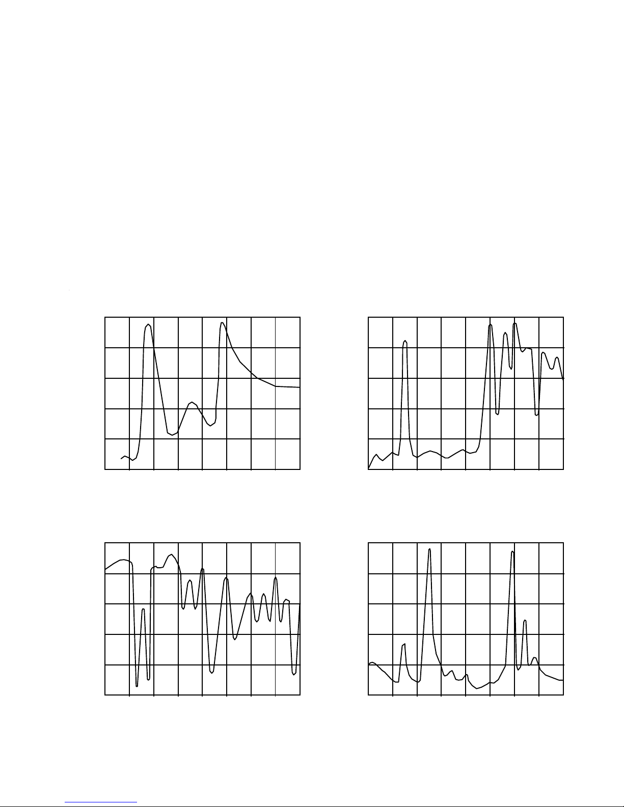
Spectral Absorption Curves
Spectral Absorption Curves:
The following spectral absorption curves show the range of wavelengths that a particular
material will absorb infrared radiation as well as the percentage of absorption. These curves are only
representative of a particular sample of a given "virgin" material. In actual practice, coloring agents and
other additives will change the look of the curves. However, the curves can be used to get a general idea
of the range of infrared radiation in which the material will absorb.
Spectral Absorption Curve For Water
100
80
60
40
Absorption, %
20
123456789
Wavelength, µm Wavelength, µm
Spectral Absorption Curve For Polystyrene
100
80
Click to add sub-title
Spectral Absorption Curve For PVC
100
80
60
40
Absorption, %
20
23456789
10
Spectral Absorption Curve For Polyethylene
100
80
60
40
Absorption, %
20
123456789
Wavelength, µm Wavelength, µm
13
60
40
Absorption, %
20
1
23456789
Page 14

Physical Properties Of Materials
Material Density Specific Emissivity Thermal Latent Latent Melting Boiling
Heat Conductivity Heat of Heat of Point Point
Fusion Evaporation
Btu Btu · in
3
lb/ft
Non-Metallic
Solids:
Asphalt 65 0.40 0.93 1.20 40 250
Beeswax 60 1.67 75 144
Carbon 138 0.20 165
Cotton 92 0.31 0.77 0.41
Glass 165 0.20 5.4
Ice 57 0.53 32
Paper 58 0.45 0.93 0.82
Paraffin 56 0.70 1.56 63 133
Rubber 76 0.44 0.90 1.10
Wood, Oak 50 0.57 0.90 1.15
Wood, Pine 34 0.67 0.90 0.90
lb·ft
2
hr · ft2 · °F Btu/lb Btu/lb °F °F
Plastics:
ABS 69-76 0.3-0.4
Acrylic 69-74 0.34
Epoxy 66-88 0.25-0.3
Flouroplastic 131-150 0.28
Nylon 67-72 0.3-0.5 Most
Phenolic 85-124 0.35 Non-Metals
Polycarbonate 74-78 0.30 Have An
Polyester 66-92 0.2-0.35 Emissivity
Polyethylene 57-60 0.54 of 0.90
Polyimides 90 0.27-0.3
Polypropylene 55-57 0.46
Polystyrene 66 0.32
PVC 72-99 0.2-0.3
Metals:
Aluminum 169 0.24 1536 1190
- Polished 0.09
- Med. Oxide 0.19
- Heavy Oxide 0.31
430 Stainless 475 0.11 150 2650
- Polished 0.17
- Med. Oxide 0.57
- Heavy Oxide 0.85
Liquids:
Oil, Cottonseed 60 0.47 0.90
Oil, Vegetable 57.5 0.43 0.90 318
Paraffin 47.1 0.71 750
Water 62.4 1.0 0.93 4.08 965 212
14
Page 15
Temperature:
°C = 5/9(°F -32) Or °F = 9/5(°C) +32
K = (°F +460)/1.8 Or K = °C + 273
°R = °F +460
Reference Data
Electrical:
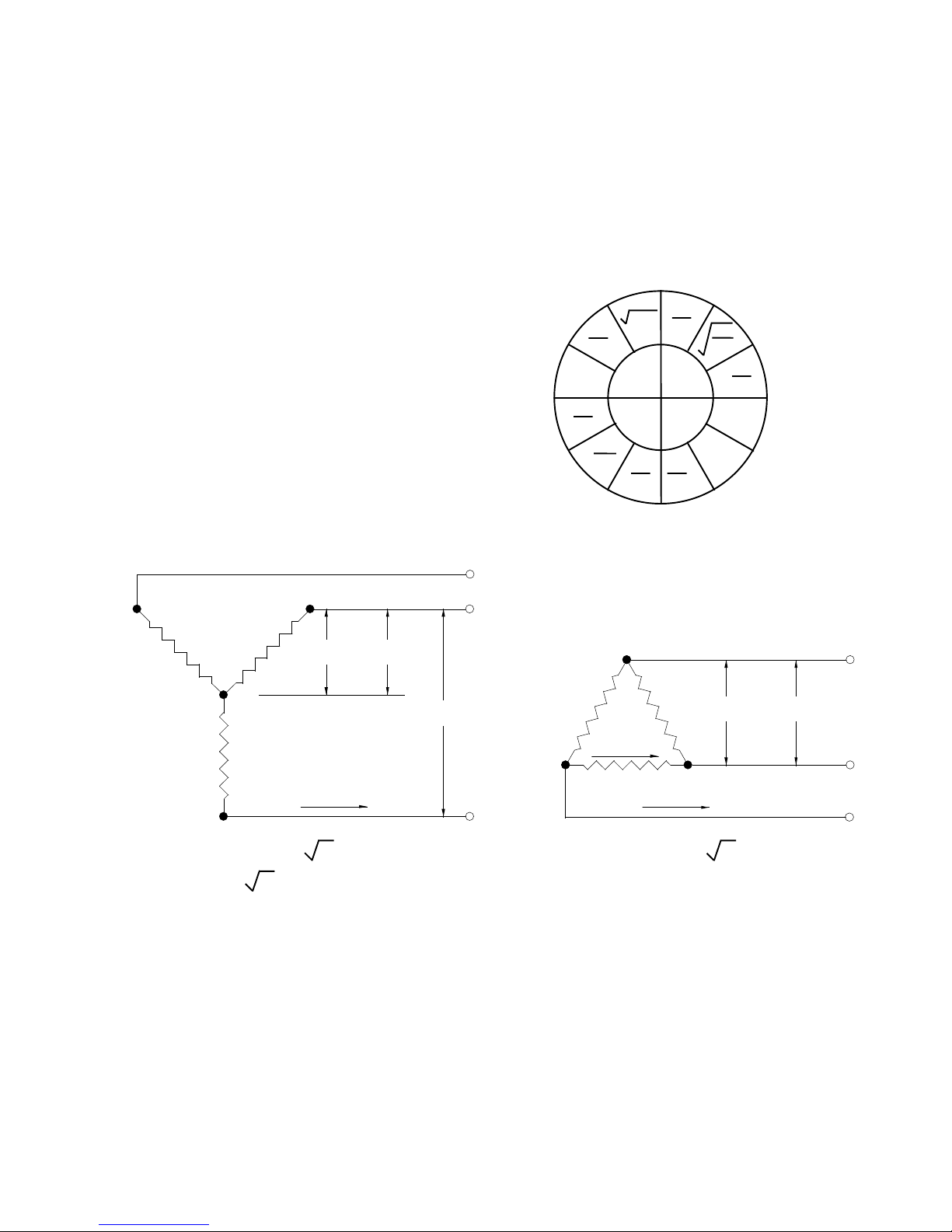
Ohms Law: E = V olts
3 Phase Wye (Balanced Load) 3 Phase Delta (Balanced Load)
I = Amps
R = Ohms
W = W atts
R(Ohm) V (Volt)
P
V (Volt)
L
IR
E
I
W
I
W
2
I
I (Amp)
P
E
WR
R
E I
R W
2
E
E
W
R
W
R
W
E
EI
2
I R
2
V (Volt)R(Ohm)
L
I (Amp)
L
W (T otal Watt) = 3 V x I
V = V / 3
R = V / I
LP
P
L
Conversion Factors:
1 KW = 1000 Watt 1mm = .03937 Inch 1kg = 2.205 lb
3412 BTU = 1 KW-HR 1m = 39.37 Inch 1g = .002205 lb
1 HP = .746 KW 1 Inch = 2.54cm 1 U.S. Gal. = .1337 Cu. Ft.
1 Boiler H.P. = 9.8 KW 1km = .6214 Mile 1 U.S. Gal. = 3.785 liters
LL
15
I (Amp)
L
W (T otal Watt) = 3 V x I
I = V / R
LP
LL
Page 16

Estimating Power Requirements
In a given heating system any or all of the three modes of heat transfer (convection, conduction,
radiation) can be utilized. The intended purpose of the following examples is to focus on the infrared
heating component only of each heating system. That is, it is assumed that 100% of the heat transfer in
each example is by infrared radiation and any heat losses are considered to be negligible.
Thermoforming:
Given: A thermoforming application requires that an 1/8" thick PVC sheet be heated
to 350 °F (177 °C) in 1 minute. Determine the power required using only
infrared radiation.
Calculations: Emissivity of the infrared source = .90
Emissivity of PVC Sheet = .90
Specific Heat of PVC = .30 BTU / lb. / °F
Density of PVC = 99 lbs. / ft
Temperature Required = 350 °F (177 °C)
Ambient Temperature = 65 °F (18 °C)
Convert the PVC target into (lbs. / in2):
lbs/in2 = (99 lbs/ft3)( 1/1728 in3)(.125 in) = .007161 lbs./in
The power required to heat the PVC sheet is given by:
Watt-Hour (Weight)(Specific Heat)( T1 - T2 )
=
in
2
3.412
(.007161)(.30)(350-65)
= = .179
3.412
3
2
16
Page 17

Thermoforming Example (cont.):
W arm-up Time:
Watt-Hour / in
2
Warm-up Time = x 60 Minutes
Watt / in
2
.179
1 min.
= x 60
Watt / in
2
Solve the "time" equation for Watt / in2:
(.179)(60)
Watt / in
2
= = 10.74
1 min
Watt / in2 = 10.74
This is the amount of infrared radiant energy that must be absorbed into
the PVC sheet to heat the sheet to 350 °F (177 °C) in 1 minute.
At this point one can use Planck's Law and the spectral absorption curve
for PVC by superimposing these curves on each other and calculating the total
area under the curves at which the two curves intersect (provided that accurate
curves are available). This can be extremely time consuming.
into the PVC sheet is given by the following:
A simplified method of estimating the power radiated and absorbed
The effective emissivity between two parallel plates is given by:
11
e = =
( 1/e
1
+ 1/e
- 1) ( 1/.9 + 1/.9 - 1)
2
= .82
17
Page 18

Thermoforming Example (cont.):
T wo infrared heater panels will be used. One panel will heat the top of
the PVC sheet, the other will heat the bottom of the PVC sheet. Heating both the
top and bottom of the PVC sheet will minimize the temperature gradient within
the sheet which could cause "part" deformation. Since two infrared panels will
be used, the power required per panel is 1/2 of the 10.74 Watts / in2. Therefore, 5.37 Watts / in
Stefan-Boltzmann Law:
2
is required from each infrared panel.
R = (.82)(36.58072 x 10
-12
)( ( T1 )
4
- ( T2 )4 ) = 5.37
Where T1 = Source Temperature
T2 = Average PVC Temperature = (65+350)/2 = 208 °F
= 371 K
Solve the equation for the source temperature.
4 5.37
T1 = + (371)
(.82)(36.58072 x 10
-12
)
4
= 667 K ( 741 °F or 394 °C)
Results: The surface temperature of the source must be at least 741°F (394 °C) to
achieve a 350 °F (177 °C) PVC sheet temperature within 1 minute.
K
18
Page 19

Water Evaporation:
Given: Estimate the amount of infrared radiation required to evaporate 4 grams of
water per square foot every 5 seconds from a substrate material in a
waterbased adhesive application. Assume the substrate to have a negligible
mass.
Calculations: Emissivity of the infrared source = .90
Emissivity of Water = .93
Specific Heat of Water = 1.0 BTU / lb. / °F
Latent Heat of Vaporization = 965 Btu / lb.
Boiling Point of W ater = 212 °F (100 °C)
Ambient Temperature = 65 °F (18 °C)
Convert the grams of water per square foot to lbs. of water per square
inch:
(4 g/ft2)(.0022046 lb/g)( 1/144 ft2/in2) = 61.24 x 10⁻⁶ lbs/in
The power required to heat the water is given by:
Watt-Hour (Weight)(Specific Heat)( T1 - T2 )
=
in
2
3.412
2
(61.24 x 10⁻⁶)(1.0)(212 - 65)
= = 2.64 x 10
3.412
(965 Btu/lb)(61.24 x 10-6 lbs/in2)
Latent Heat of Vaporization =
3.412
= 17.32 x 10
-3
Total Power Required = (2.64 x 10⁻³) + (17.32 x 10⁻³)
Watt - Hr
= 22.60 x 10
-3
in
2
-3
19
Page 20

Water Evaporation Example (cont):
W arm-up Time:
Watt-Hour / in
2
Warm-up Time = x 60 Minutes
2
-3
2
5/60 min.
Watt / in
22.6 x 10
= x 60
Watt / in
Solve the "time" equation for Watt / in2:
(22.6 x 10⁻³)(60)
Watt / in
2
= = 16.27
5/60 min
The effective emissivity between two parallel plates is given by:
11
e = =
( 1/e
1
+ 1/e
- 1) ( 1/.9 + 1/.93 - 1)
2
= .84
Stefan-Boltzmann Law:
R = (.84)(36.58072 x 10
-12
)( ( T1 )
4
- ( T2 )4 ) = 16.27
Where T1 = Source T emperature
T2 = A verage Water Temperature = (65+212)/2 = 138.5 °F (59 °C)
= 332.5 K
Solve the equation for the source temperature.
4
16.27
T1 = + (332.5)
(.84)(36.58072 x 10
-12
)
4
K
= 858 K = 1084 °F (584 °C)
Results: The surface temperature of the source must be at least 1084°F (584 °C) to
evaporate 4 grams of water within 5 seconds.
20
Page 21

Notes:
21
 Loading...