

Mor Electric Heating 303, 305, 304, CRH, CRQ Installation And Operation Instructions Manual
...
INST ALLATION AND OPERATION INSTRUCTIONS
303, 304, 305, CRH, CRQ, CF A SERIES
CAUTION: To prevent electric shock disconnect power to heater at main service before
wiring or service.
CAUTION: Do not obstruct the front of the heater with curtains, furniture, doors,
etc. Do not place heaters under towel racks. Proper operation of the
heater requires a free flow intake and exhaust of air.
Warning:
To insure proper operation, all heaters must be thermostatically
controlled.
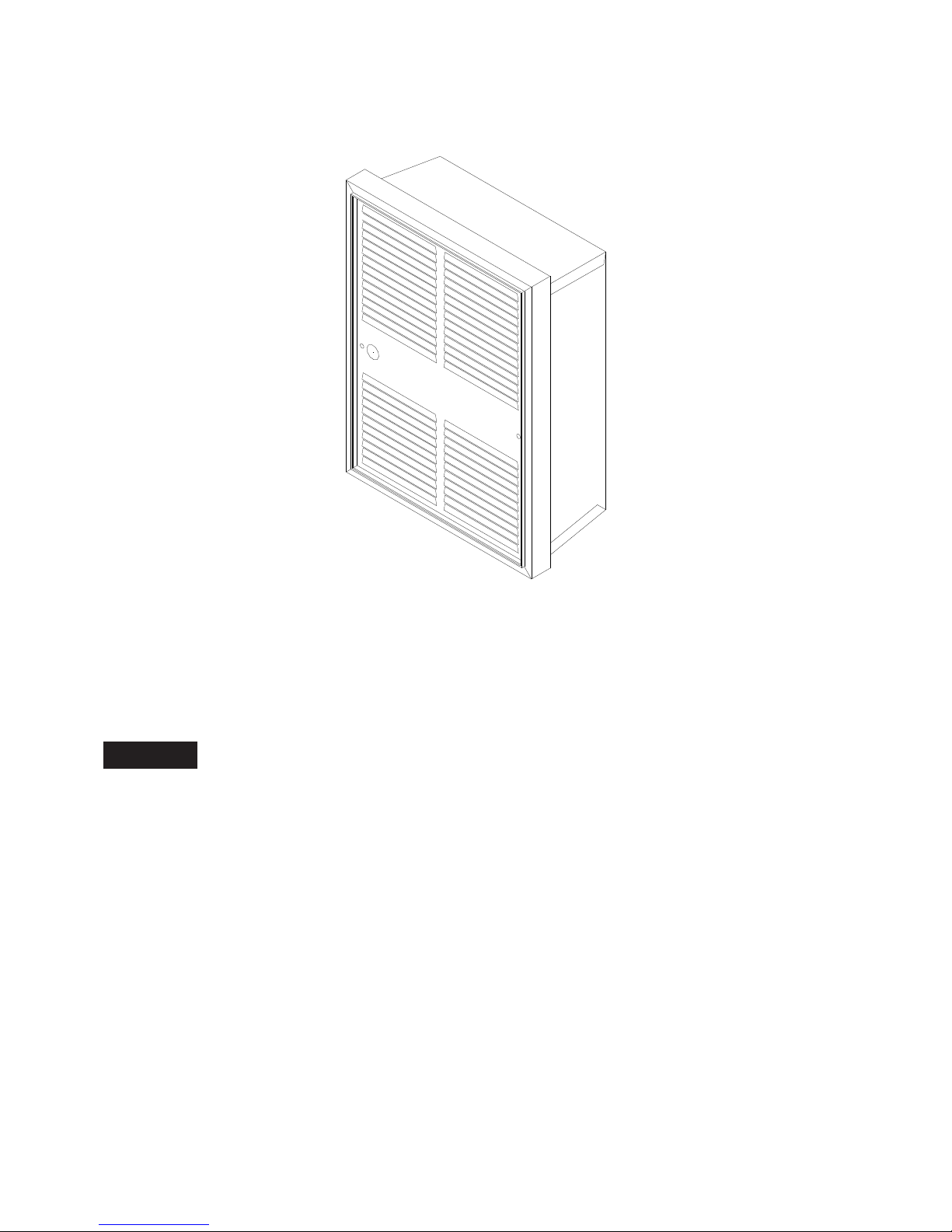
GENERAL
These heaters are designed for 2 X 4 recessed or surface mount installation. The heaters may be wall
mounted in a vertical or horizontal position and ceiling mounted. The minimum clearance from wall box to
adjacent wall or floor is 6 inches. These heaters must not be installed without wallbox model no. 30WB.
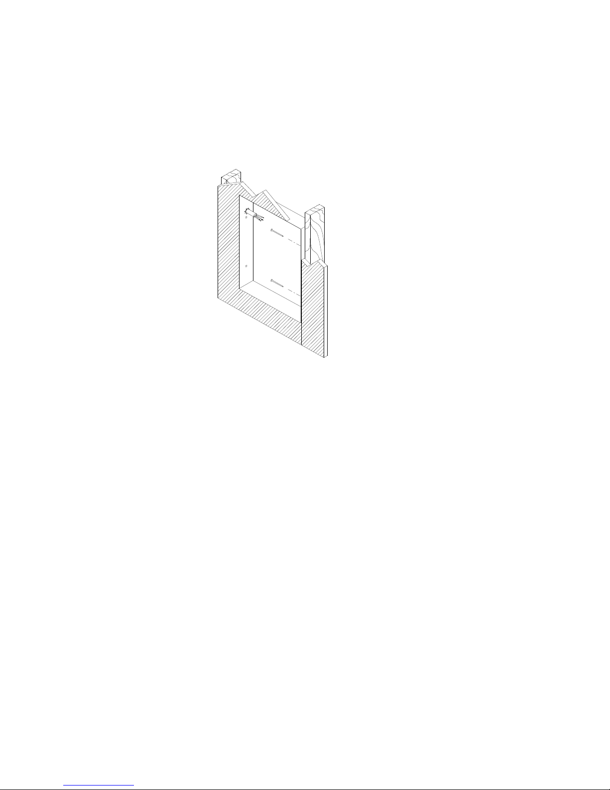
INST ALLATION OF WALL BOX 30 WB
FOR NEW CONSTRUCTION
1.Position wall box a minimum of 6 inches from ajacent wall and floor. Secure to wall stud with nails or
screws. Wall box must be installed with front edge flush with finished wall surface. See figure 1.
2.Remove knockout in wall box for power source, and install cable clamp.
3.Insert supply cable through clamp allowing 6-8" for field wiring.
NOTE: Field wiring must enter wall box where the corner wiring compartment is located.
Form 9940
Rev. 01/06
1
INST ALLATION OF W ALL BOX 30WB
FOR EXISTING CONSTRUCTION
1. Carefully cut a hole measuring 9 ¼” wide by 12 ¼” long in wall. Wall box 30WB must be attached to a
wall stud on one edge. Minimum clearances of 6" must be maintained to adjacent surfaces. Attach wall
box and secure power cable as in new construction.
FIG. 1
FIELD CONVERSION FOR LOWER W ATTAGE
To convert heater to a lower wattage rating. Remove red jumper from heating element (see figure 2). The
wattage will be reduced to half of the nameplate wattage. See specification chart for available wattage.
INST ALLATION OF HEA TER ASSEMBLY
1. Place heater into wall box and secure with the two no. 8 x ¾ screws provided.
2. Connect power supply to heater pigtails with wirenuts or crimp terminals.
3. After field connections are made, push wires into wiring compartment and secure wiring
compartment cover to heater using no. 8 X ½” screw provided.
INSTALLATION OF GRILLE AND KNOB
1. Place the two no. 8 oval head screws into grille mounting holes.
2. Align grille with heater and secure. Be careful not to over tighten as this may cause fan blade to
strike grille.
3. To install knob, remove hole plug in grille and align flat of thermostat shaft with flat on knob. Push
knob onto shaft until knob almost touches grille.
4. For tamper-resistant installation, set thermostat with knob, remove knob and replace hole plug.
Retain knob for future use.
Form 9940
Rev. 01/06
 Loading...