

Page 1

Morel Ardon Bookshelf Speaker Kit
Thank you for purchasing the More Ardon bookshelf speaker kit. This speaker kit was precision
cut using CNC machinery for the best possible fit and finish. With a little time and patience, your
finished product will provide years of enjoyment. Please follow the following instructions for the
best possible results.
Suggested tools and consumables:
Drill Rag or paper towels
5/64" drill bit Solder
Wood clamps (you can never have too many of these) Soldering iron
Sanding block and/or electric finishing sander Hot glue gun
Wood glue Polyurethane glue (Gorilla Glue)
0.11" female disconnect terminal Cyanoacrylate Adhesive (super glue)
0.205" female disconnect terminal
Package contents:
First, empty the contents of the package and review parts to ensure everything has been included
and is in good condition. If any parts are missing or damaged please contact our customer service
department at 1-800-338-0531.
Note: Crossover components may be substituted with parts of equal of higher quality depending
on stock.
Components:
A) Morel KW-1 6" Damped Poly Cone Woofer
B) Morel KT-1 1-1/8" Neodymium Soft Dome Tweeter
C) 2" ID Adjustable Port Tube
Page 2
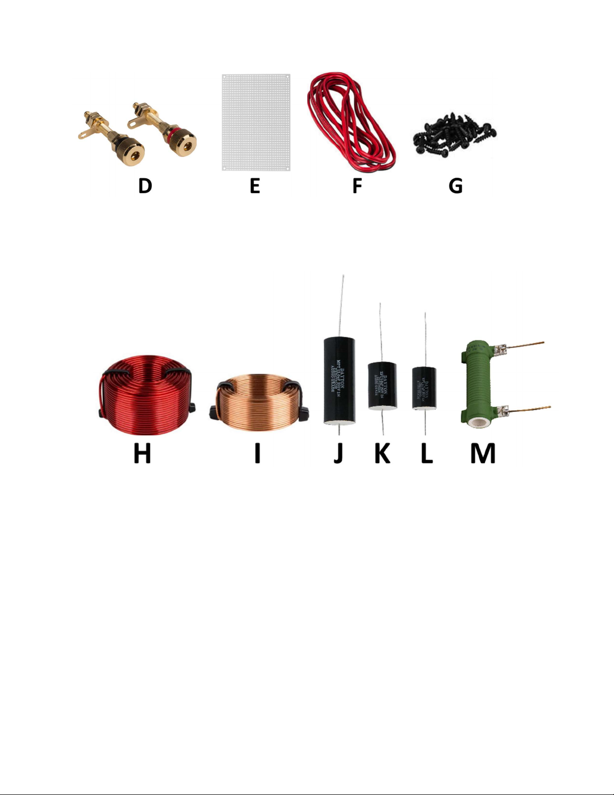
D) Dayton Audio BPA-38G HD Binding Post Pair Gold
E) White Perforated Large Hole Crossover Board 3.5" x 5"
F) 16 AWG 2-conductor Power Speaker Wire 4 ft. (Red/Black)
G) 25-Pack #6 x 3/4" Pan Head Deep Thread Black Screws
H) Dayton Audio LW141 1.0mH 14 AWG Perfect Layer Inductor
I) Dayton Audio AC20-40 0.40mH 20 AWG Air Core Inductor Coil
J) Dayton Audio PMPC-12 12uF 250V Precision Audio Capacitor
K) Dayton Audio PMPC-5.6 5.6uF 250V Precision Audio Capacitor
L) Dayton Audio PMPC-4.7 4.7uF 250V Precision Audio Capacitor
M) Dayton Audio DPR20-4.7 4.7 Ohm 20 Watt Precision 1% Audio Grade Resistor
Enclosures:
N) Front
O) Back
P) Top
Q) Bottom
R) Sides x 2
S) Vertical Brace
T) Horizontal Brace
Page 3
Enclosure Assembly:
1) First, before gluing anything, do a dry fit of the enclosure to familiarize yourself with the
parts and assembly. This will also give you a chance to ensure that all pieces have been cut
properly.
2) Due the design of this enclosure, it can easily be assembled in one sitting, using as little as 6
clamps.
3) Begin by setting the enclosure parts out on a flat level surface and ensure that all pieces are
free of dust and debris.
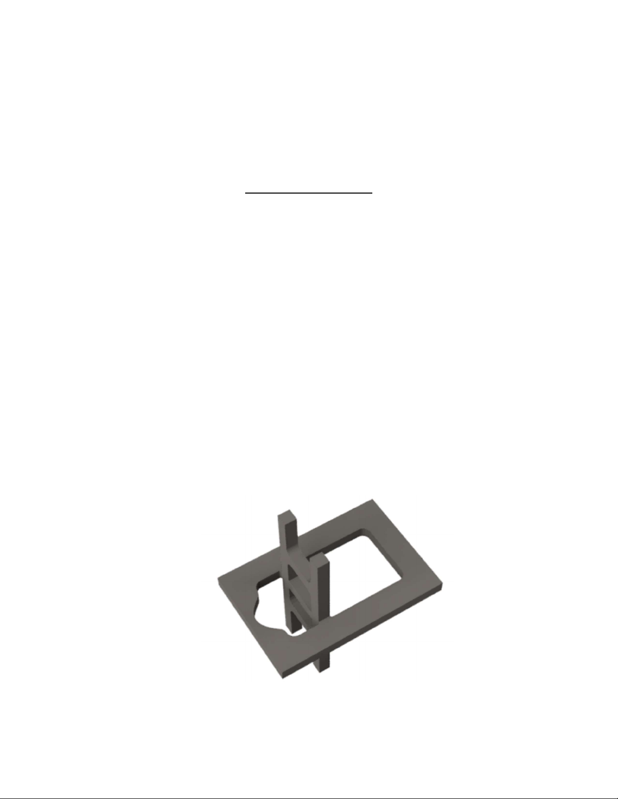
4) Glue all mating surfaces of the notches in the Horizontal Brace and Vertical Brace and
assemble as shown to complete the Brace Assembly. Ensure that the notches are seated
completely. Light clamping pressure can be applied while preparing the next step, but should
not be necessary.
Page 4
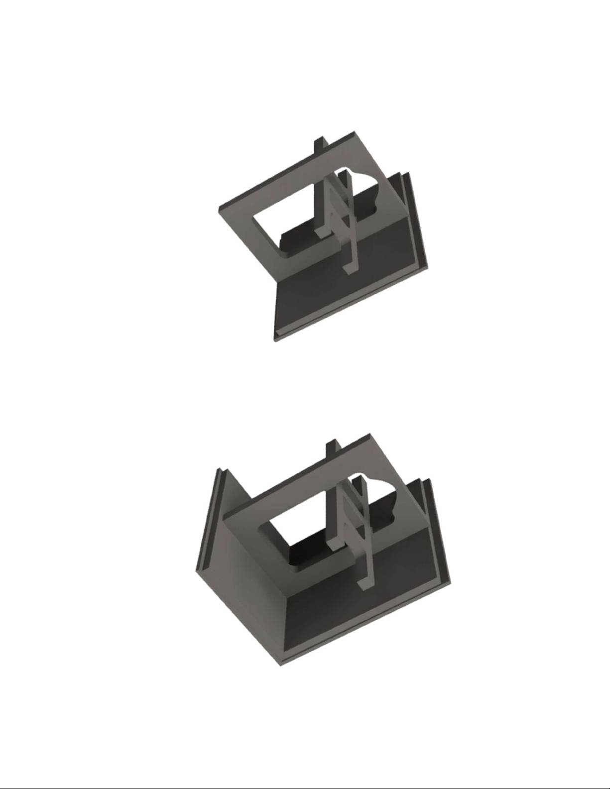
5) With one Side Panel laying flat, glue all mating surfaces of the dado in the Side Panel and
one side of the Brace Assembly. Insert the Brace Assembly as shown. Make sure the Brace
Assembly is seated completely in the dado.
6) Glue all mating surfaces of Bottom Panel, Side Panel, and Brace Assembly. Insert the
Bottom Panel as shown. Make sure the Brace Assembly is seated completely in the dado on
the Bottom Panel.
Page 5
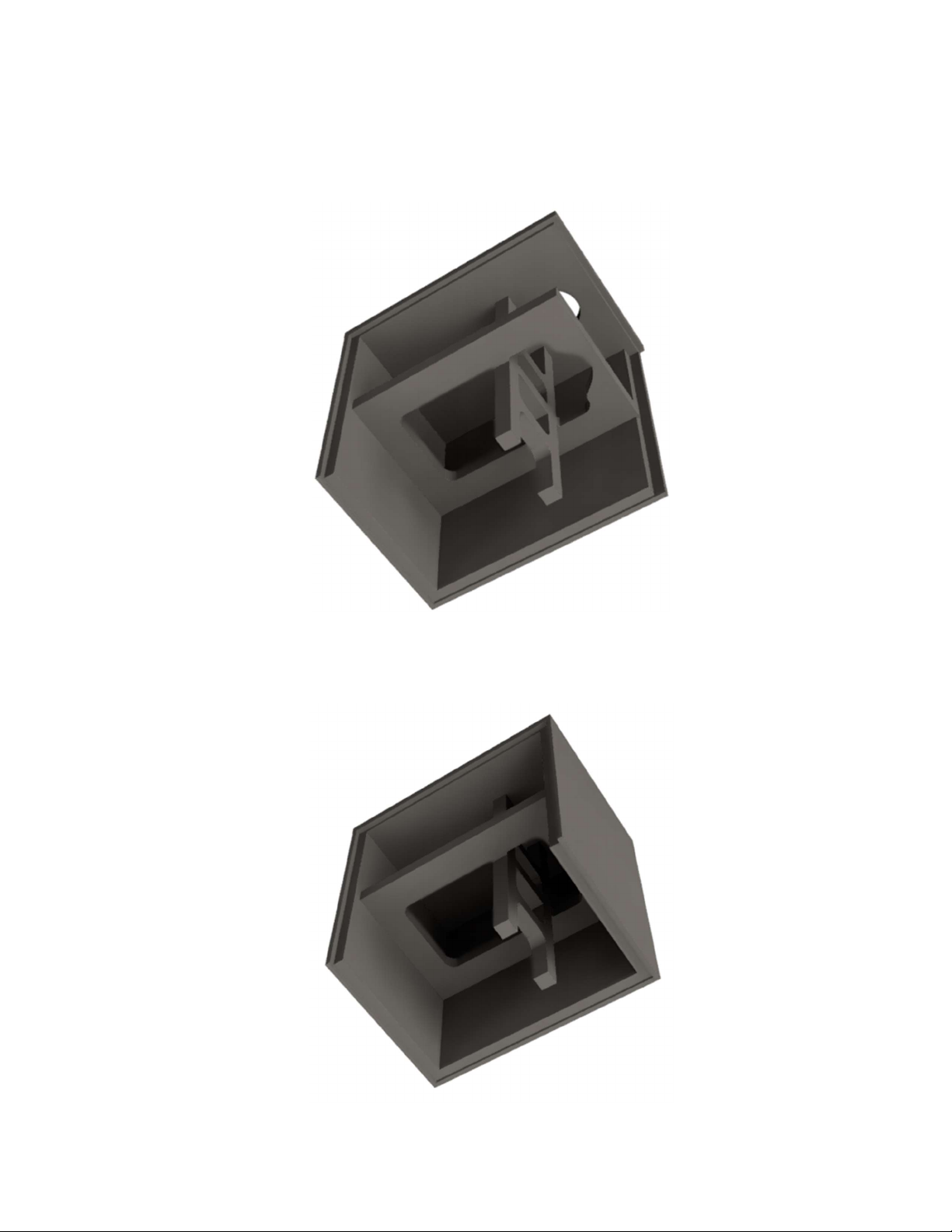
7) Glue all mating surfaces of the Back Panel, Bottom Panel, Side Panel, and Brace
Assembly. Insert the Back Panel as shown. Make sure the Brace Assembly posts are seated
completely in the matching notches on the Back Panel.
Note: Make sure the port cutout is lined up with the notch at the top of the brace assembly.
8) Glue all mating surfaces of Top Panel, Side Panel, Back Panel, and Brace Assembly. Insert
the Top Panel as shown. Make sure the Brace Assembly is seated completely in the dado on
the Top Panel.
Page 6
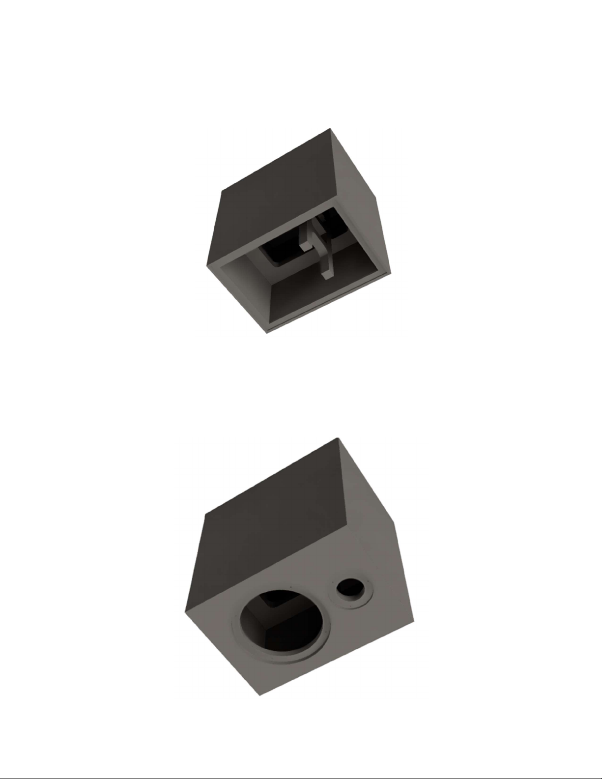
9) Glue all mating surfaces of the second Side Panel, Top Panel, Bottom Panel, and Brace
Assembly. Insert the second Side Panel as shown. Make sure the Brace Assembly is seated
completely in the dado on the second Side Panel.
10) Glue all mating surfaces of the Front Panel, Bottom Panel, Side Panels, and Brace
Assembly. Insert the Front Panel as shown. Make sure the Brace Assembly posts are seated
completely in the matching notches on the Front Panel.
Note: Mare sure the tweeter cutout is lined up with the notch in the top of the brace
assembly.
Page 7
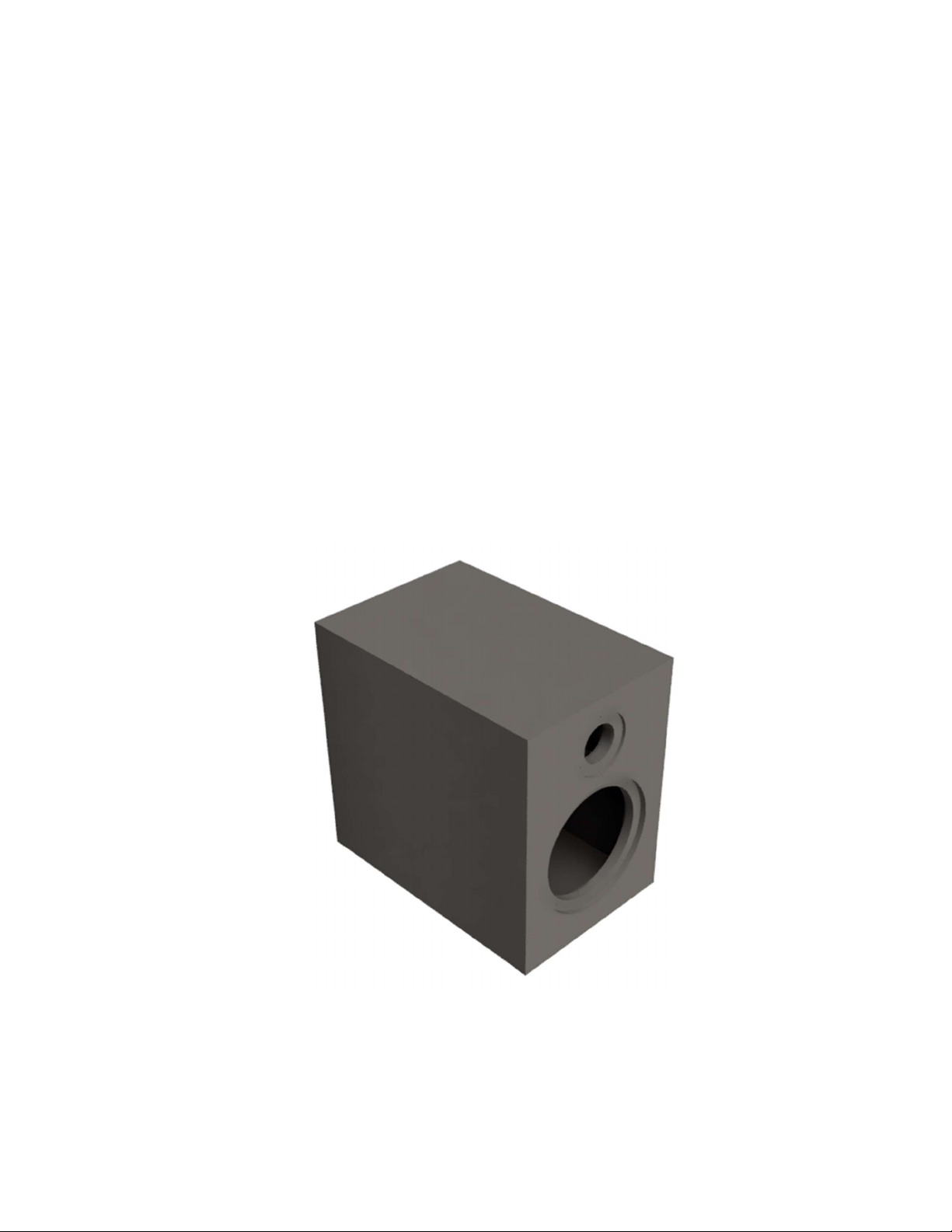
11) Make sure that all edges are flush and securely apply clamps from side to side, top to bottom,
and front to back. Apply ample pressure to ensure glue is spread evenly through each joint
(some glue squeeze-out can be expected). Visually inspect all seams to make sure they are all
closed tightly, you may need to relocate clamps (or add more clamps) to get a perfect fit.
12) Wipe away any glue squeeze-out on the outside of the enclosure with a damp rag or paper
towel (excess glue on the inside is fine). Allow to dry according to the glue manufacturer's
recommendations and remove clamps.
13) Finally, fill any open seams with wood filler or a mixture of sawdust and wood glue. Then
sand all surfaces and seams until smooth. Finish enclosure to your liking. See our web page
for ideas and examples.
Page 8
Crossover assembly:
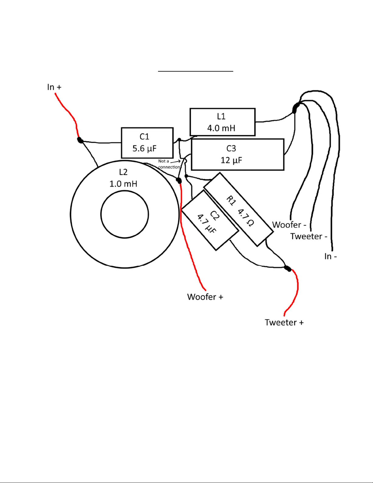
Point-to-point wiring diagram
14) Arrange the components on the White Perforated Crossover Board as illustrated in the point-
to-point wiring diagram above so the leads can be connected together as shown on the back
side of the board. Take careful note of the component type and the value of the component.
(The crossover schematic is provided at the end of this assembly guide.)
15) Connect the leads of the components as shown in the diagram by twisting them together or
creating interlocking "hooks" with the leads. Double check your layout to ensure all
components are in the proper location and connections are correct.
Note: The component leads should be long enough to make the C1, L1, R1, C2 connection
underneath C3 to keep leads from crossing.
Page 9
16) With a hot soldering iron, apply solder to the connections between components. Heat the
junctions evenly and verify that the solder flows into the connections rather than forming a
"blob" on the surface (cold joint).
17) Cut two lengths of 2-conductor speaker wire approximately 14"-16" in length, then solder
them at the outputs of the crossover network labeled "woofer" and "tweeter" in the schematic
so that the marked polarity of the wire matches the driver polarity shown in the schematic
(red to "+" and black to "-"). Label each wire "woofer" or "tweeter" corresponding to the
schematic.
18) Next cut one length of 2-conductor speaker wire approximately 6"-10" in length. Solder this
wire to the "input" connections of the crossover network as shown in the schematic so that
the marked polarity of the wire matches the input polarity in the schematic. Label the length
of wire "Input".
Note: You may find it easier to solder all the negative (-) connections at once. This
connection may require a lot of heat, so take your time and be patient when making this
connection.
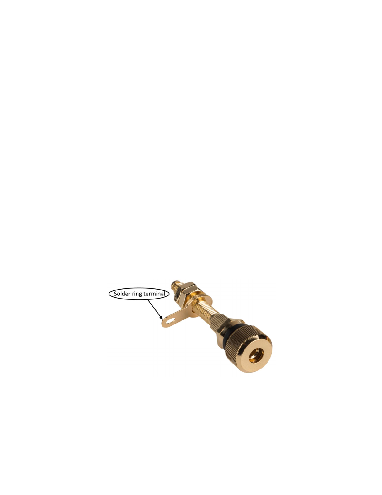
19) Finally, remove the nuts and solder ring terminals from the Dayton Audio BPA-38G HD
Binding Posts. Solder the open ends of the input wires to the solder ring terminals.
Page 10

Final Assembly:
20) Mark the desired location of the Dayton Audio BPA-38G HD Binding Posts (3/4" on center
is the standard spacing if you are using dual banana plugs). Drill a 1/4" hole for each binding
post. Insert the binding posts and tap into place using a mallet or hammer (make sure the bare
wire holes in the binding posts are pointing in the direction you desire). Attach one of the
included nuts and tighten to secure the posts in place.
Note: If using a hammer place a wooden block between the hammer and binding post to
avoid damaging the finish on the binding post.
21) Insert crossover through woofer hole and glue crossover to the bottom of the enclosure
(polyurethane glue, high temperature hot glue gun, or epoxy is recommended). Ensure all
crossover components are securely held in place to prevent rattles. Attach the solder ring
terminals to the corresponding binding posts. Secure the solder ring terminals to the binding
posts using the remaining included washers and nuts.
22) Port installation is simple. Slide the adjustable end of the port onto the flanged end and glue
in place at the desired length using any glue that is acceptable for use on plastic (super glue,
plastic cement, hot glue, et c…). Insert the assembled port into the enclosure and screw into
place using the included #6 x 3/4" Pan Head screws. The recommended port length is 7". The
length can be adjusted to your taste, a shorter port will result in slightly less bottom end with
a tighter punch.
23) Connect tweeter wires to tweeter terminals while observing polarity and set tweeter in place.
Using a screwdriver, secure the tweeter using the included #6 x 3/4" Pan Head screws, just
until tight, being careful not to strip out the holes (a power drill is not recommended).
24) Connect woofer wires to woofer terminals while observing polarity and set woofer in place.
Using a screwdriver, secure woofer using the included #6 x 3/4" Pan Head screws, just until
tight, being careful not to strip out the holes (a power drill is not recommended).
25) You are now ready to enjoy your finished Morel Ardon bookshelf speaker.
Page 11
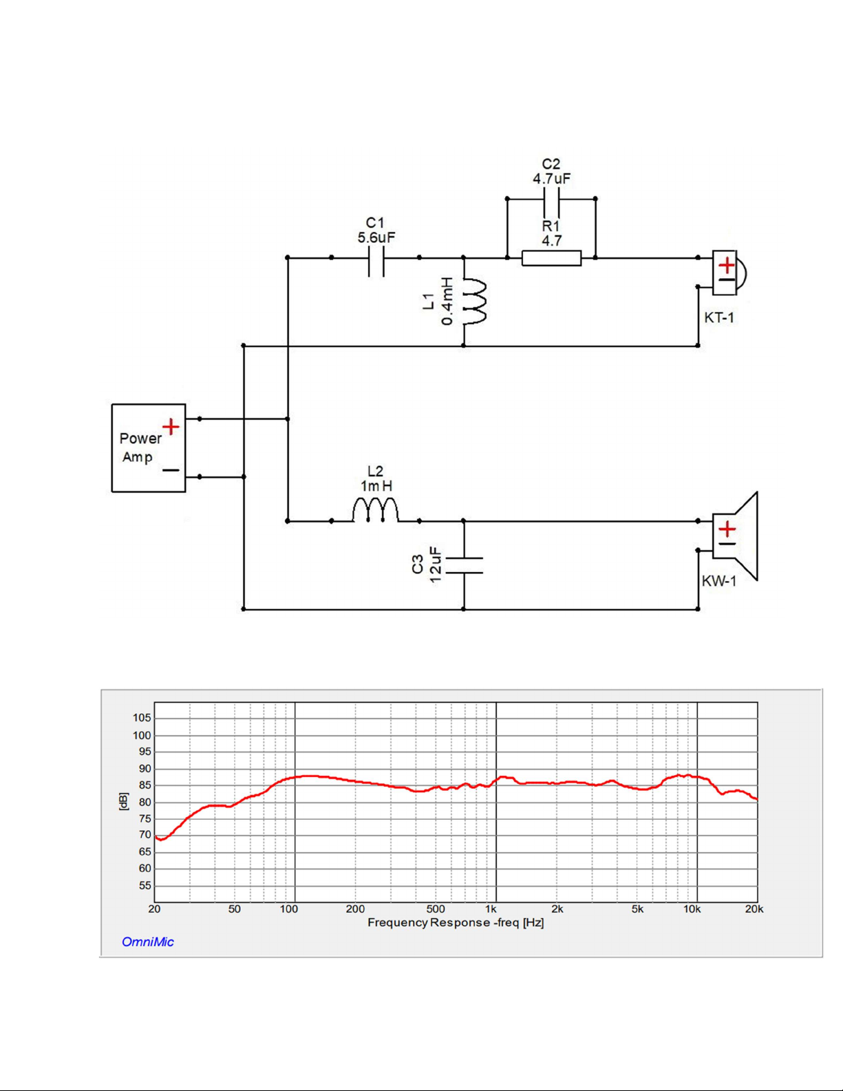
Morel Ardon Crossover Schematic:
Morel Ardon Frequency Response
1M/2.83V
 Loading...