

Page 1

H. H. MØRCH
DP-6
Instructions
Contents of the packing
In the packing of the tonearm you will find the arm base in which the bearings are encapsulated in a
heavy body. This is the link between the moveable part of the tonearm and the arm pillar, which is to
be mounted in a bush in the board of the turntable.
Further you will find one arm tube according to the choice that you have had from literature about the
tonearm or from advice of your dealer. There also will be 4 weights, finger lever with screws, knurled
nut, hexagon spanner, and a syringe with silicone fluid.
The tonearm usually is supplied with the arm rest mounted on the pick-up lifter, but if desired a
separate arm rest could be supplied instead.
Mounting the bushes
First it has to be decided exactly where to place the bush in which the tonearm is to be mounted. The
center of the bush should be at a distance of 212 mm (8 5/16 '') from the center of the turntable platter
and there has to be room enough for the counterweight rod to move freely. The counterweight rod is
having a rear overhang of 70 mm (2 3/4 ") as to the center of the arm bush. If separate arm rest is
used, it should be placed so that the arm when resting on it is at a suitable distance from the record.
The mounting template on the packing of the tonearm is showing the position of the arm base and the
arm rest as to the turntable spindle. It should be noted that the position of the turntable spindle shown
is just an example. In order to allow for the most convenient position of the arm base the turntable
spindle could have its center anywhere on the arc shown.
Mark the center of the arm bush and check that the distance to the center of the turntable platter is 212
mm (8 5/16 "). Then drill a 20 mm (13/16 ") hole with center in this mark. Also, if separate arm rest is
used, drill a 10 mm (13/32 ") hole for the bush for the arm rest about 155 mm (6 1/8 ") in front the 20
mm hole.
Fastening the two bushes: In order to make it easy to adjust the height of the arm and the arm rest with
the accompanying hexagon spanner, the small screws for fixing the arm and the arm rest should point
to the right.
Then the arm base is fastened in the arm bush. See Fig. 1.
Mounting the cable to the amplifier
Put the plug of the tonearm cord into the socket inside the bottom of the arm pillar. Make sure that the
big nut holding the arm base is tightened before pushing the connector of the tonearm cord into the
arm base. Try to avoid bending the cable too sharply right next to the tonearm connector. If the
turntable has a floating sub chassis, the cable should not be restricted in any way, and it should be
arranged in a suitable arc, so that it does not limit the free movements of the suspension. Remember
that the ground wire should always be connected to the chassis (ground terminal) of the amplifier. The
chassis of the turntable in most cases also has to be electrically connected to the arm base.
Choice of weights and putting them on
In order to make it possible to balance all phono cartridges the tonearm is supplied with three
counterweights - large, medium, and small - having the hole eccentrically positioned and with a
tracking force weight having a centrally positioned hole.
Page 1
Page 2
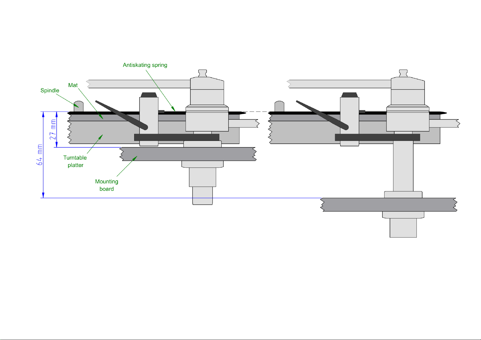
Fig. 1. Horizontal view of the mounted tonearm.To adjust the vertical tracking angle (VTA), raise or lower the armbase
so that the antiskating spring is approximately aligned with the surface of the record. If the vertical distance between
the mounting board and the record surface is below approx. 27 mm, then the turntable platter should be raised or, if this
is not possible, padding should be added between the turntable platter and the mat.
Page 2
Page 3

The weights that are to be chosen for balancing a cartridge depend on which arm tube that is to be
Light arm tube
Medium
Heavy
“Green”
“Red”
“Blue”
1.2-2.4
small only
1
2.5-6.5
0.5-4.3
small + tf.
2
5.2-7.6
3.0-5.4
medium + tf.
2
7.6-12.7
5.4-10.2
medium + small + tf.
2
9.0-9.9
7.0-7.6
large + tf.
2
11.9-21.2
9.9-15.4
0-4.8
large + small + tf.
2
19.0-21.2
17.0-19.4
6.5-9.0
large + medium + small + tf.
2
used and on the weight of the cartridge.
The weights to be used can be found in the below table (tf. means tracking force weight).
Start putting onto the counterweight rod the largest counterweight you are going to use. Then the the
smaller one etc. and last the tracking force weight. To put on the counterweight/s and to displace
them along the counterweight rod they have to simultaneously be revolved to and fro.
Weight of cartridge in grams – (1 column per armtube): Counterweight combination: Note:
Notes:
1. Here the small counterweight is used as tracking force weight.
2. Here both the tracking force weight and the counterweight/s are used to adjust the tracking force.
The large counterweight gives 2 g, the medium counterweight gives 1.2 g, the small counterweight
gives ½ g and the tracking force weight gives ½ g when slid 1 indentation forwards.
Thus a certain tracking force can be obtained by sliding more than one weight adding up their shares of tracking
force.
.
Refilling the silicone fluid
The accompanying syringe contains about 0.6 ml of silicone fluid. The pick-up lifter should be filled in.
Pull the black piston out of the lifter cylinder and place it in a completely clean place. Then inject 0.05
ml but absolutely no more than 0.1 ml of the fluid behind the lifter handle shaft inside the lifter cylinder. When doing this the lifter handle must be in "lowered" position.
When the fluid is injected, the tip of the syringe is "wiped off" on the shaft, and the syringe is pulled up
with a little jerk thereby preventing the fluid from getting in touch with the walls of the lifter cylinder. Do
not put the piston back into the lifter cylinder until the silicone fluid has merged down to the bottom of
the cylinder, and hereafter the piston must not be pulled up again, as the silicone fluid would then
easily stick to the walls of the lifter cylinder. If this happens the piston will descend much too slowly.
The horizontal mode of motion is damped by the factory. Damping of the vertical mode of motion almost never
is an advantage. If damping for the vertical mode of motion is desired anyway, special instructions for doing this
can be supplied.
Mounting the cartridge
Using the accompanying finger lever the cartridge can now be mounted on the armtube. If possible, use the
accompanying aluminum screws. Provided that the tonearm is mounted, so that the distance from the pivot to the
center of the turntable is as indicated on the mounting template, the position of the stylus - to obtain correct
overhang - should be: with standard armtubes right under the front edge of the black plane of the armtube - with
PRECISION armtubes 4 mm (5/32”) behind the front edge. Also the cartridge should be in parallel to the said
black plane. Carefully push the terminal jacks of the wires unto the pins of the cartridge with a pair of tweezers.
Do not force them too much and also see that you are not squeezing the thin wiring too hard. Red and green
are signal and ground of right channel. White and blue are signal and ground of left channel.
Page 3
Page 4

The flange of the armtube having 5 contact pins now is pushed down on the threaded rod on top of the
arm base. It is fastened with the accompanying knurled not, which should be tightened well with two
fingers. Check that the overhang is correct - 18 mm (23/32”) - and adjust if necessary. The easiest way
to check that the overhang is correct is to put a ruler on the turntable platter, so that one of its sides
touches the turntable spindle. Then turn the turntable platter, so that the said side of the ruler points to
the center of the knurled nut on top of the armtube. Then the armtube is moved so that the stylus is
brought on line (above the said side of the ruler) with the direction from the center of the turntable
spindle to the center of the said knurled nut. The distance from the center of the turntable spindle to
the stylus (overhang) can be accurately observed by looking at the scale of the ruler between the stylus
and the turntable spindle. Look at right angles to the ruler. Of course an alignment protractor will help
to align more accurately.
Adjusting the tonearm
Adjust the height of the arm base so that the antiskating spring is at level with the record.
Put the tracking force weight near the end of the counterweight rod. Move the counterweight/s
backwards or forwards until the arm tube is balancing in about horizontal position. When doing this see
that there is space to move a counterweight forwards to apply tracking force. The large counterweight
gives 2 g when moved 1 indentation forwards. The medium counterweight gives 1,2 g when moved 1
indentation forwards and the small counterweight gives ½ g when moved 1 indentation forwards.
Rotate the counterweight/s so that the center of gravity is pointing upwards. It also could point
downwards. The two settings influences the room of the stereo image.
Apply tracking force by moving a counterweight and/or the tracking force weight forwards. If not all the
tracking force is applied by moving a counterweight forwards, then also slide the tracking force weight
forwards. Moving the tracking force weight forwards 1 indentation will give ½ g tracking force. When
adjusting the weights they should be arranged, so that there is space on the counterweight rod to move
the tracking force weight forwards and backwards. This will make it easy to audition the best setting of
the tracking force.
Use as many counterweights as possible, but still there has to be room for the tracking force weight to
move.
If it appears that one counterweight can not get far enough forwards to obtain the correct tracking
force, then also – if more than one counterweight is used - move another counterweight and/or the
tracking force weight. If there is not enough space to move the weights forwards to give the correct
tracking force a counterweight should be replaced by a smaller one..
The height of the tonearm now should be fine adjusted. With the stylus resting on a record the arm base is
moved downwards or upwards until the arm tube is in parallel to the record, and the arm base is turned so that
the pick-up lifter can always support the arm tube. The screw in the arm bush then is tightened with the accompanying hexagon spanner.
If the arm rest is mounted on the pick-up lifter, it should - when adjusting the position of the arm base - be
considered that the arm rest should allow the arm tube to rest in a suitable distance from the record.
The height of the pick-up lifter is adjusted so that the stylus is about 4 mm (5/32”) above the record, when the
pick-up lifter is in "raised" position. Use the screw in front of the black plate holding the pick-up lifter.
If separate arm rest is used, it is adjusted in a height, so that the arm tube rests on it, when the pick-up lifter is in
"raised" position.
Cartridge azimuth
Azimuth (inclination of stylus as seen from the front) may have to be adjusted. When the stylus is
resting on a record, the stylus - and so the cartridge - should stand at a right angle as to the record.
If it does not, put the long end of the hexagon key from the plastic container into the hole in the right
Page 4
Page 5
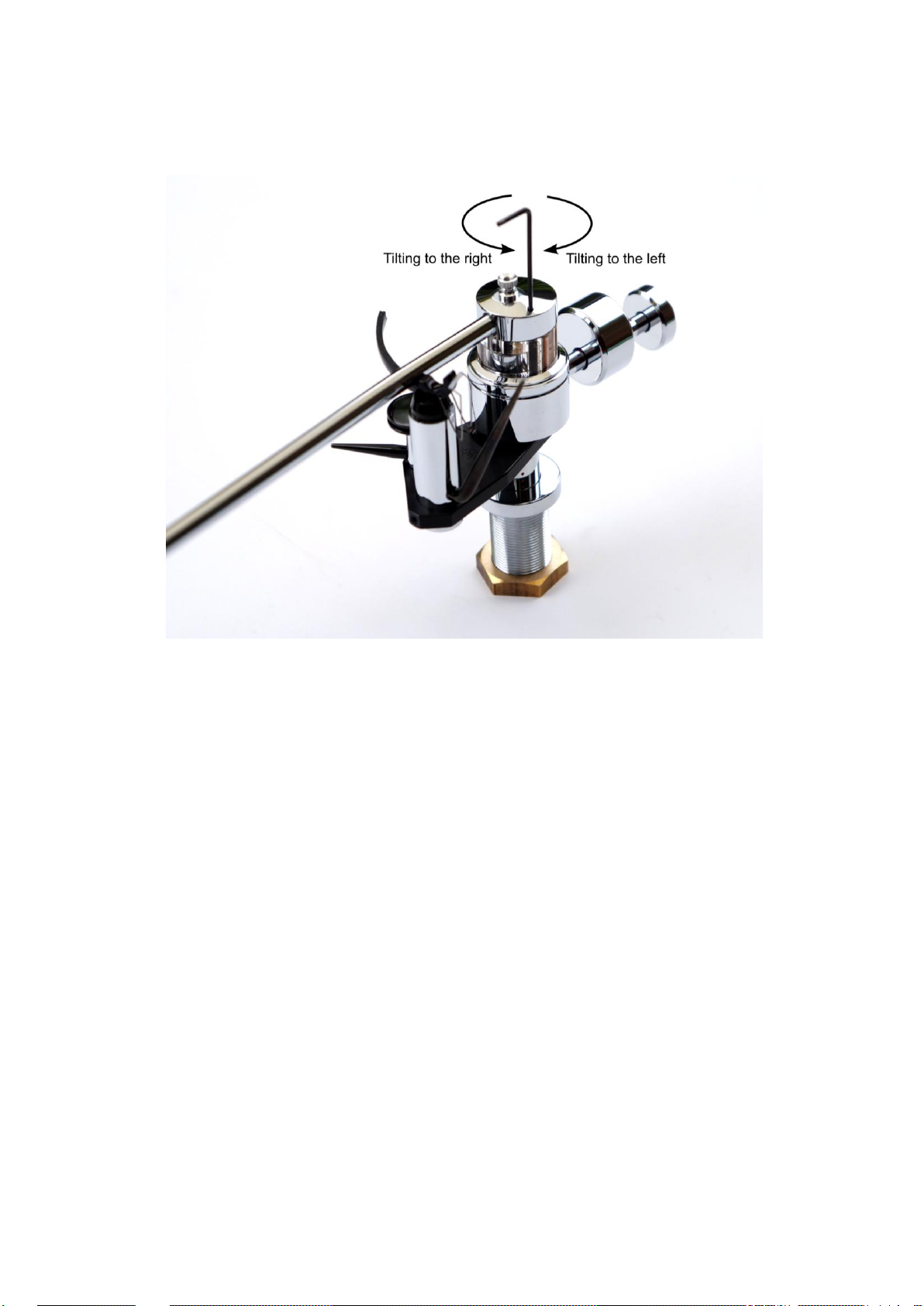
side of the flange of the armtube next to the knurled nut holding the armtube. See that the key
“catches” the hexagon hole in the screw on top of the arm base. (See fig. 1.)
By turning the hexagon key clockwise the arm - and so the cartridge - will be tilted to the left. By turning
it counter clockwise the cartridge will be tilted to the right. Look at the front of the cartridge and the
mirror image of it in the record. They have to be on line.
Fig. 1. The hexagon key, going through the armtube flange, is ready to turn the pivot up or down.
Lateral balance
The direction of the counterweight rod extended to the stylus should be the line of lateral balance. Coarse
adjustment can be done by turning the counterweights on the counterweight rod, so that their center of gravity is
pointing upwards or downwards and about 30° to the right as seen from the end of the rod.
Fine adjustment can be done by raising the moveable part of the tonearm. A match or the hexagon spanner
could be used holding it horizontally under the counterweight rod as close to the body of the arm base as
possible and using it to raise the moveable part of the tonearm about l mm off its bearings.
When doing this the arm tube should rest on the raised pick-up lifter, and the anti skating spring should be
pushed, so that it does not pull the tonearm.
When raising the moveable part of the tonearm as described above, both sides of the arm base should raise
simultaneously. If one side is too light and comes up first, the "heavy end" of the counterweight/s should be
turned a little in the direction of the side, where the arm is too light. Then try again to raise with the match, a.s.o.
until both sides comes up simultaneously.
Antiskating
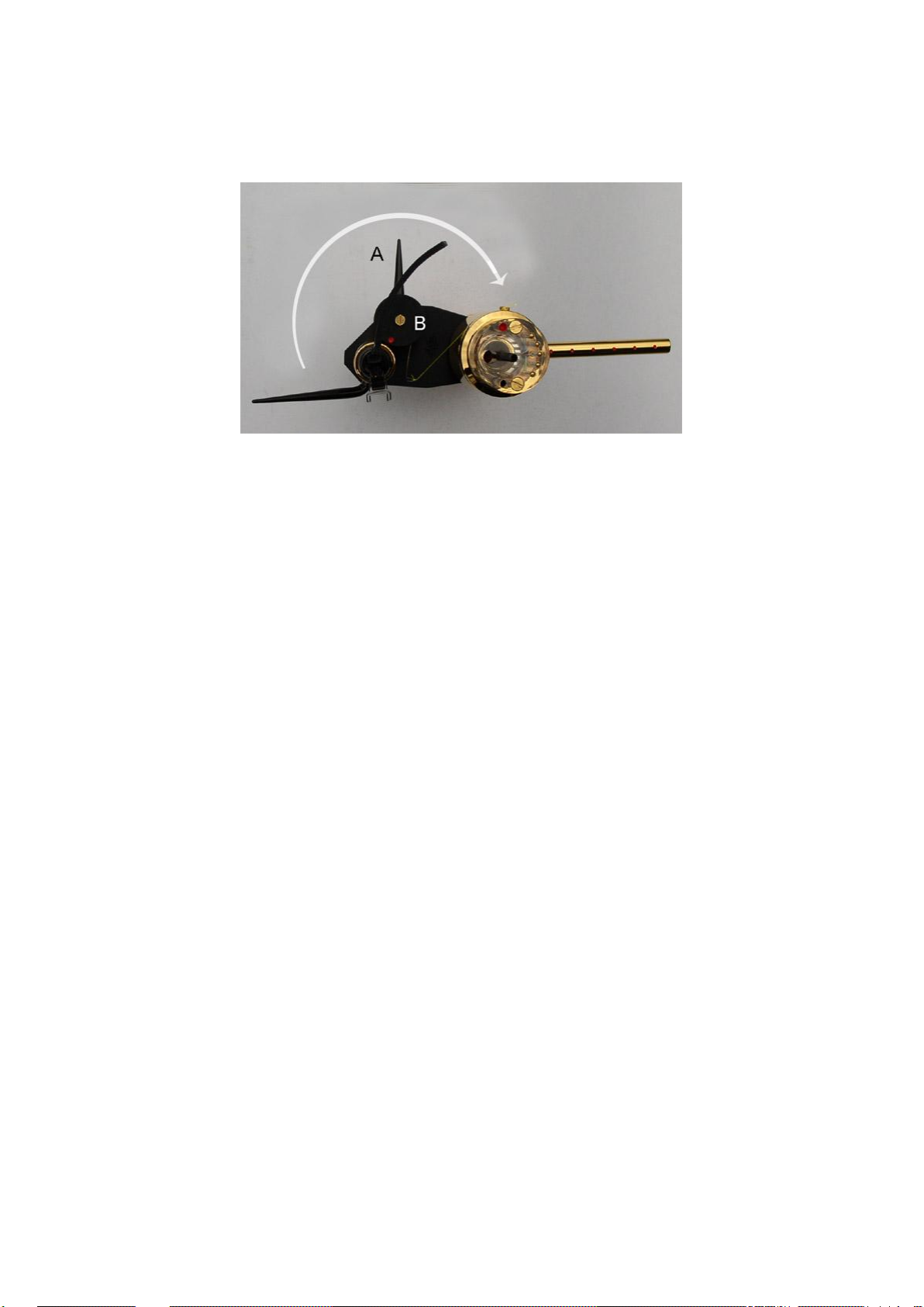
The antiskating force is adjusted with the little black handle A next to the pick-up lifter. The amount of antiskating
force required depends on the tracking force and the shape of the stylus. Thus no calibration is possible.
Coarse adjustment can be done with the stylus running between the grooves next to the label of the record.
Correctly adjusted, the stylus should move slowly towards the center of the record.
Page 5
Page 6
Fine adjustment could be done by reducing the tracking force a little whilst listening to a critical passage. If for
instance distortion occurs in the right speaker, the handle should be turned clockwise. (The best result is
obtained with a test record). The adjustment is not critical. It is better giving too little than too much antiskating
force.
The range that the antiskating handle A can move, will cover most cartridges.
If the handle A is turned in the direction of the arrow the antiskating will increase - and decrease if it is
turned the opposite way. If the handle cannot be turned enough to get more antiskating or to get less
antiskating the disc under the screw B should be adjusted. Hold it with two fingers of the left hand,
while the screw B is loosened with a screwdriver, and the disc is turned ½ revolution or more either in
the direction of the arrow if more antiskating force is desired or in the opposite direction. Then the
screw should be tightened again. The antiskating then can be adjusted with the handle A in a range
with more or less antiskating than before.
Special about PRECISION arm tubes
PRECISION arm tubes are supplied in "red" and "blue" versions only. They have a wide and very
precisely ground mounting plane to assure a good mechanical contact to cartridges that have a similar
large and accurate mounting plane. The PRECISION armtubes are 4 mm (5/32”) longer than the
standard ones in the forward direction.
Special about 12” armtubes
12” arm tubes are supplied in "red" and "blue" versions only. They are supplied only with the narrow
headshell.
In the section Mounting the bush it is described how the position of the 20 mm (13/16”) hole is found.
For 12” armtubes the distance from the center of this hole to the center of the turntable patter should
be 294.1 mm (11 9/16”).
If the bush is mounted at above distance from the center of the turntable platter, the stylus should be
positioned a little behind the front edge of the black plane of the arm tube. After mounting check that
the overhang - 13.3 mm (17/32”) - is correct and adjust if necessary.
With 12” armtubes more counterweights should be used than with 9” armtubes. With the heaviest 12”
armtube “blue” usually all the weights should be on the counterweight rod. If even the cartridge is
heavy, the weights should be put on in opposite sequence, so that the large counterweight is at the end
of the counterweight rod.
The sound image most likely will be the best, if the counterweights are adjusted with the center of
gravity above the counterweight rod.
Page 6
 Loading...