

Page 1
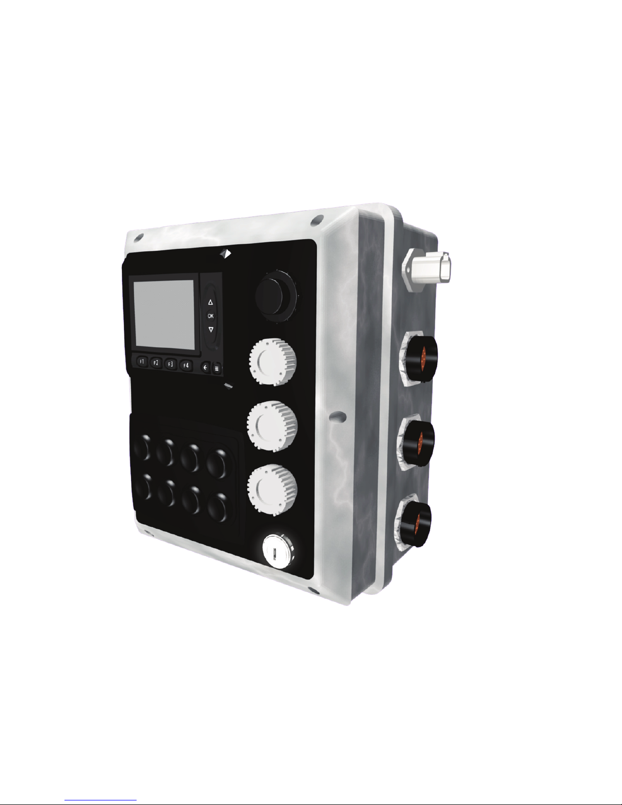
Operator’s Manual
Morbark Integrated Control System
Model 20 Chipper
Page 2

Page 3

Contents
Introduction iv
Parts Identification 6
Display Module Display Pages 9
Main Page 11
Engine Information Page 12
Feed Control Page 13
Control Devices Page 14
Performance Adjustment Pages 15
AutoFeed Settings Page 17
Control Select Page 18
Menu System 19
Accessing the Menu 21
Sub-Menus 23
Adjust Menu 25
Measure 26
Preferences 27
Info 28
Troubleshooting 31
Page 4

Introduction
Introduction
This manual was designed to provide a better understanding of the Control Panel that
comes installed on your Machine. Each page of the Display Module, as well as any
adjustable values, will be described in detail.
Contained within:
Part Identification of:1.
Control Panel•
Display Module•
Display Pages 2.
Display Module Menu System3.
Parameter Adjustments4.
Troubleshooting5.
Each “Display Page” is shown exactly as it is on the Machine. This should make it
easier to follow along when troubleshooting issues in the field. Also, every page has a
section describing what each button on the Display Module does and the corresponding
page number for that specific function.
iv
Operator’s Manual, Morbark Integrated Control System—Model 20 Chipper
Page 5

Cautions and Warnings
Warning: Before welding on the Machine, ensure that
all connectors are disconnected from the control panel.
Failure to do so could result in damage to the panel itself
or its components.
Warning: Disconnect all power before making any wiring
connections to the control panel.
Caution: Improper operation of these controls could cause
damage to equipment. Do not allow anyone to operate
this equipment before completely reading the manual.
Caution: Electronic controls are intended as general purpose switches. They are not safety devices. Malfunctions
may occur.
Caution: Electronic products are used to initiate an
operation where false operation could be dangerous.
Point-of-operation guarding devices must be installed and
maintained to meet OSHA and ANSI Machine safety standards. The manufacturer shall not accept responsibility for
installation, application, or safety of systems
Operator’s Manual, Morbark Integrated Control System—Model 20 Chipper
v
Page 6
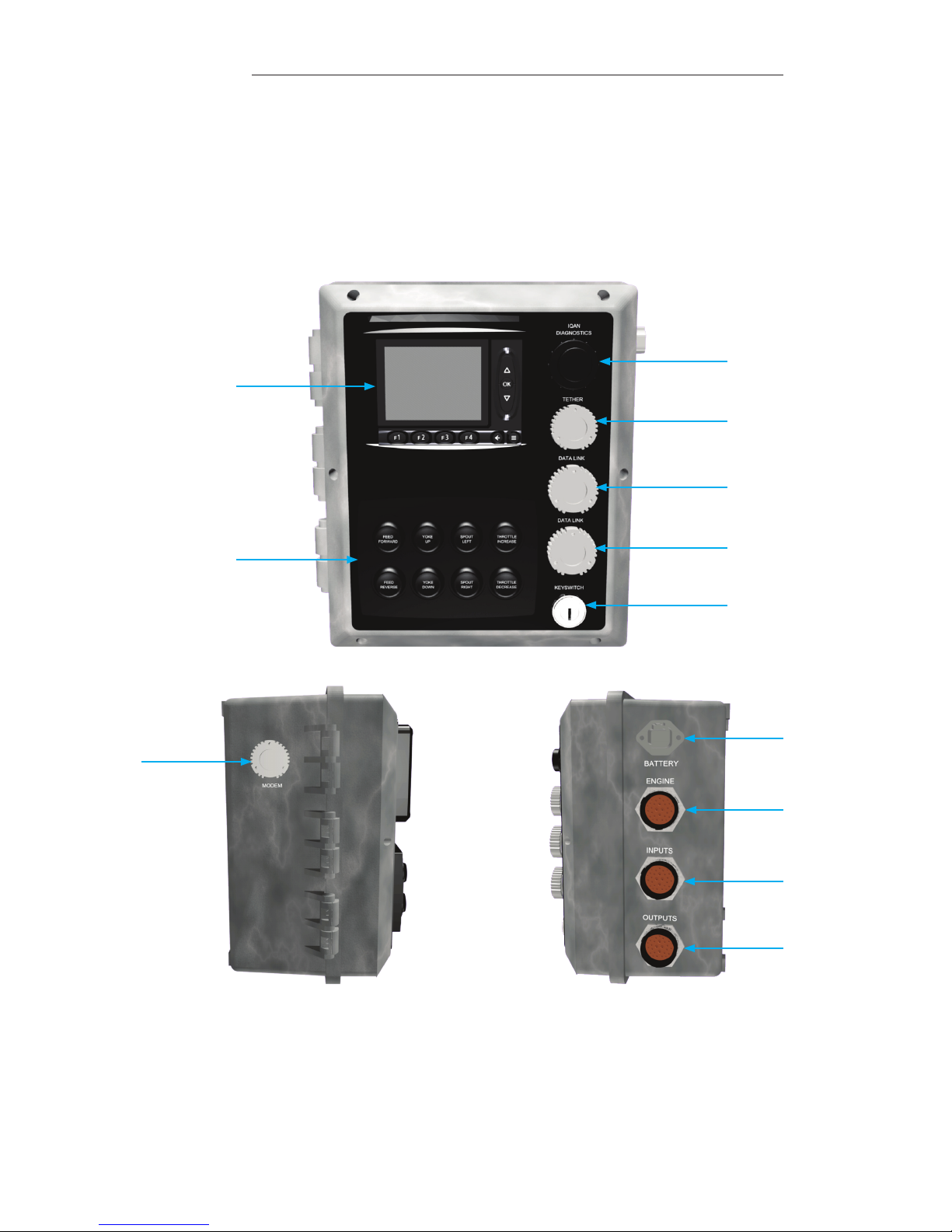
Parts Identification
Parts Identification
This section describes all connectors and switches located on the exterior of the control
panel, valve driver and the Display Module.
Control Panel Front View
1
3
4
5
2
6
7
Control Panel Right ViewControl Panel Left View
9
8
10
11
12
6
Operator’s Manual, Morbark Integrated Control System—Model 20 Chipper
Page 7

Panel / Valve Driver Parts Identication
No. Description
1
Master Display Module
2
Manual Controls / Keypad
Feed Forward — Engage the Feed System•
Feed Reverse — Reverse the Feed System•
Yoke Up — Raise the Yoke•
Yoke Down — Lower the Yoke•
Spout Left — Rotate the Spout Left•
Spout Right — Rotate the Spout Right•
Throttle Increase — Increase the speed of the Engine•
Throttle Decrease —Decrease the speed of the Engine•
3
Diagnostics Connector
4
Tether — Connection Point for the Tether control
5
Cat Data Link
6
John Deere or Cummins Data Link
7
Key Switch
8
Modem Option Connector
9
Battery connector — To “Main Disconnect” and Negative (-) post on Starter
10
Engine Connector — Connects to the Engine on the Machine
11
Input Harness Connector
Hood Switch•
Feed Stop•
Feed Bar Proximity Switch•
Fuel Gauge•
12
Output Harness connector
Feed Forward•
Feed Reverse•
Yoke Up•
Yoke Down•
Right Track Forward•
Right Track Reverse•
Left Track Forward•
Left Track Reverse•
Spout Left•
Spout Right•
Winch In•
Winch Out•
Track Drive High•
Track Drive Enable•
Fan Reverse•
Parts Identification
Operator’s Manual, Morbark Integrated Control System—Model 20 Chipper
7
Page 8
Parts Identification
1
7
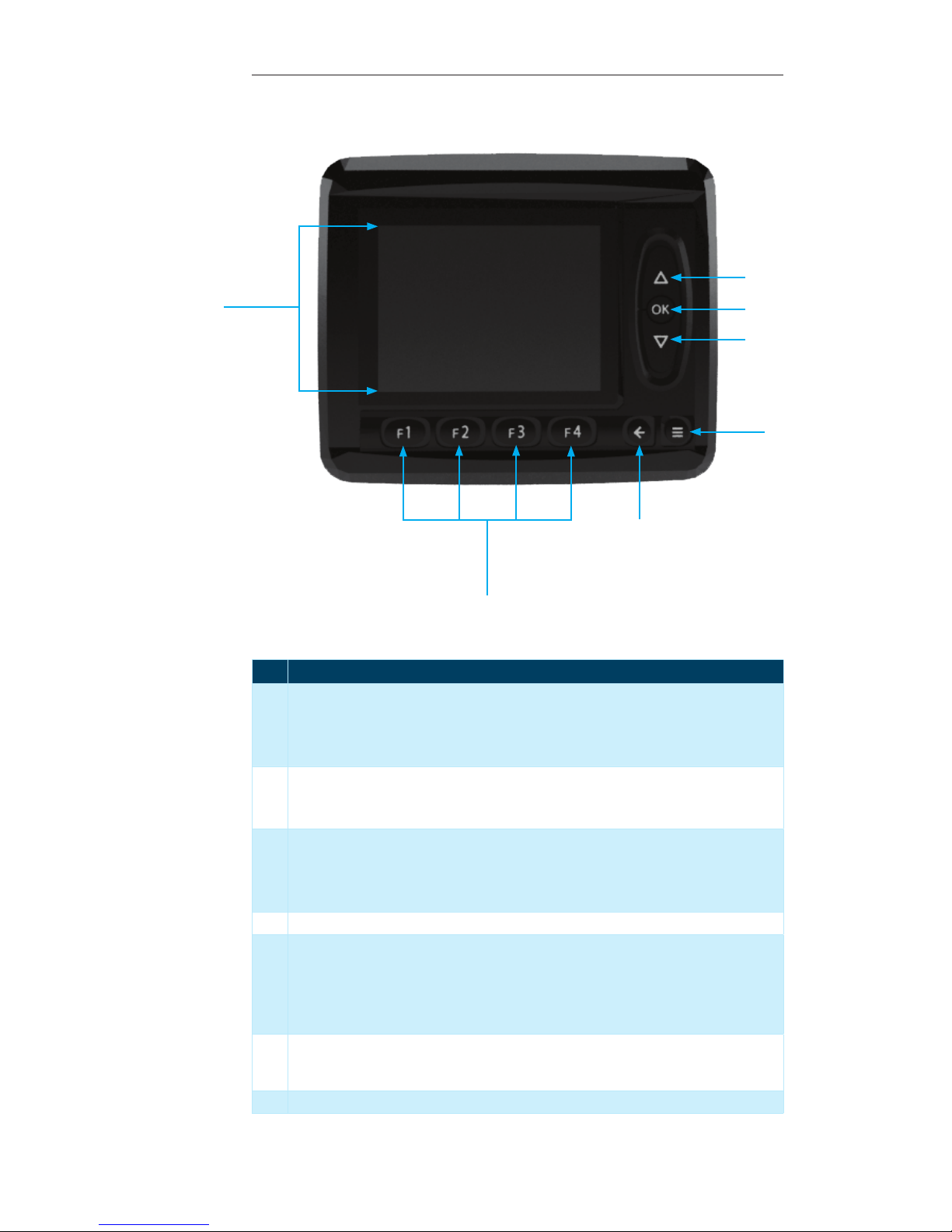
Display Module Parts Identication
No. Description
1 “Up” button — This button is used to navigate through the following:
Display Pages•
Menus•
Lists (i.e. selecting “Grinding Mode” or other adjustable parameters)•
2 “OK” button — This button is used as follows:
To navigate to the “Main Page” from any “Display Page”•
To confirm a selection within an adjustable screen (i.e. to set the “Grinding Mode”)•
3 “Down” button — This button is used to navigate through the following:
Display Pages•
Menus•
Lists (i.e. selecting “Grinding Mode” or other adjustable parameters)•
4 “Menu” button — This button is used to access the “System Menu”. It can be used at any time.
5 “Escape button — This button can be used as follows:
To cancel a selection•
Navigate to the “Main Page” from within any “Display Page” •
Escape from the “System Menu” to the “Display Page” that was being viewed prior to enter-•
ing the “System Menu”
6 “Function” buttons — These buttons can be used from within any page in the system. Their
functionality is dependant on the page that is currently displayed. A more in-depth description will be given on a per-page basis.
7 Display Screen
2
3
4
5
6
8
Operator’s Manual, Morbark Integrated Control System—Model 20 Chipper
Page 9

Display Module Display Pages
Display Module Display Pages
Main Page 11
Engine Information Page 12
Feed Control Page 13
Control Devices Page 14
Operator’s Manual, Morbark Integrated Control System—Model 20 Chipper
9
Page 10

Display Module Display Pages
Each “Disp lay Page” will have the
option to change the “Control
Device” for the Machine. To
change between different options
perform the following steps:
Press the “F4” button, this will
open th e “Control Selec t” page.
Press the “F1” button to change
the contro l device
Use the “Up/Down” buttons to
select t he desired contr ol device
When the green light is o n next to
the desired control device press
the “OK” button
Press the “F4” bu tton to return to
the previous page
Introduction
This section covers the main “Display Pages”. A listing of every parameter displayed on
each page as well as the “unit of measure” for those items will be provided.
Contained within this section:
Main Page — The first page to be displayed when the system is powered up. Shows
•
some key Engine Parameters.
Engine Information Page — Displays information related to the Machine’s Engine•
Feed Control Page — Displays parameters of the Machine’s Feed Control System.•
Control Devices Page — Displays Part Numbers, Serial Numbers and, if applicable,
•
Channel of the Machine’s Control Devices (Panel, Radio Transmitter and Tether)
10
Operator’s Manual, Morbark Integrated Control System—Model 20 Chipper
Page 11
Display Module Display Pages
Main Page
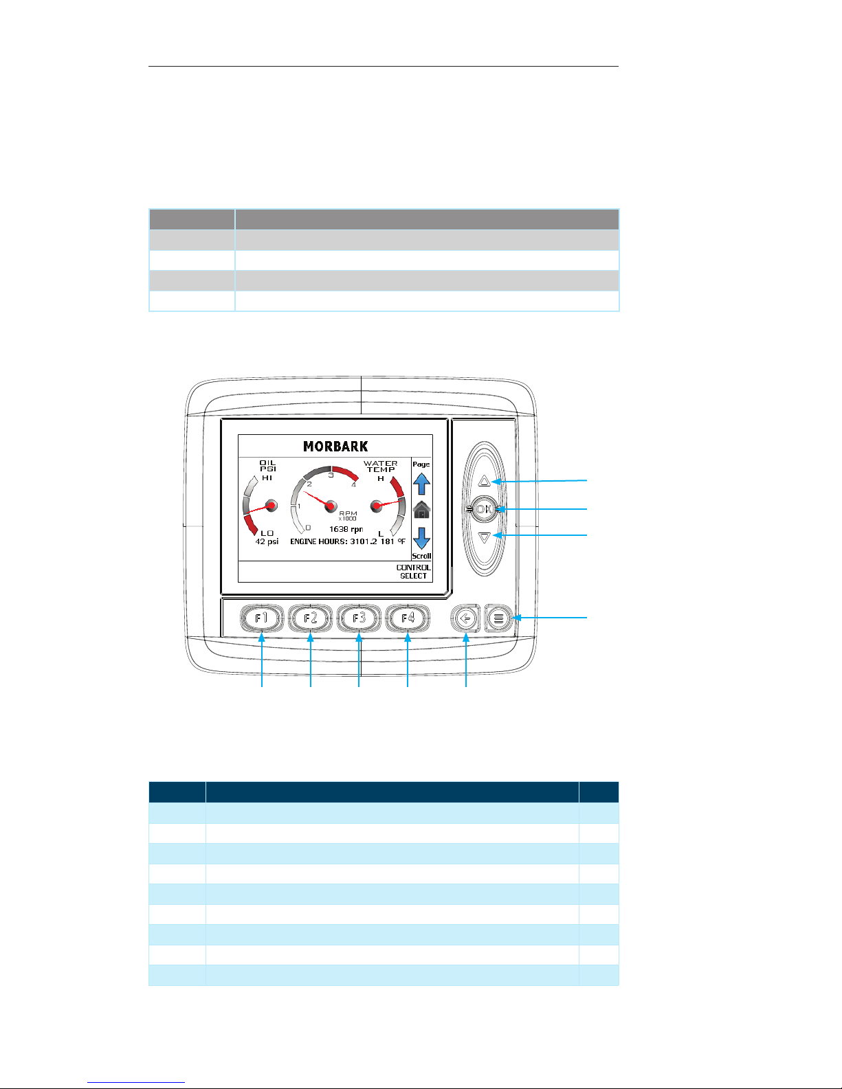
This is the first page to be displayed when the panel is powered up. While in the main
“Display Pages” of the system, this page can be reached by pressing the “OK” button,
the “Escape” button or scrolling through the pages using the “UP/Down” arrows.
Contained within this page:
Parameter Unit of Measure
Engine speed RPM
Oil pressure PSI
Water temp ° Fahrenheit
Engine hours Hours
1
2
3
4
56789
Display Module Navigation
Number Description Page
1 Up Arrow — Press to navigate to the “Engine Info” Page 12
2 OK Button — Not used on the current screen --
3 Down Arrow — Press to navigate to the “Control Devices” Page 14
4 Menu Button — Press to navigate to the “System Menu” 21
5 Escape Button — Not used on the current screen --
6 F4 Button — Press to navigate to the “Control Select” Page* 18
7 F3 Button — Not used on the current screen --
8 F2 Button — Not used on the current screen --
9 F1 Button — Not used on the current screen --
Operator’s Manual, Morbark Integrated Control System—Model 20 Chipper
11
Page 12
Display Module Display Pages
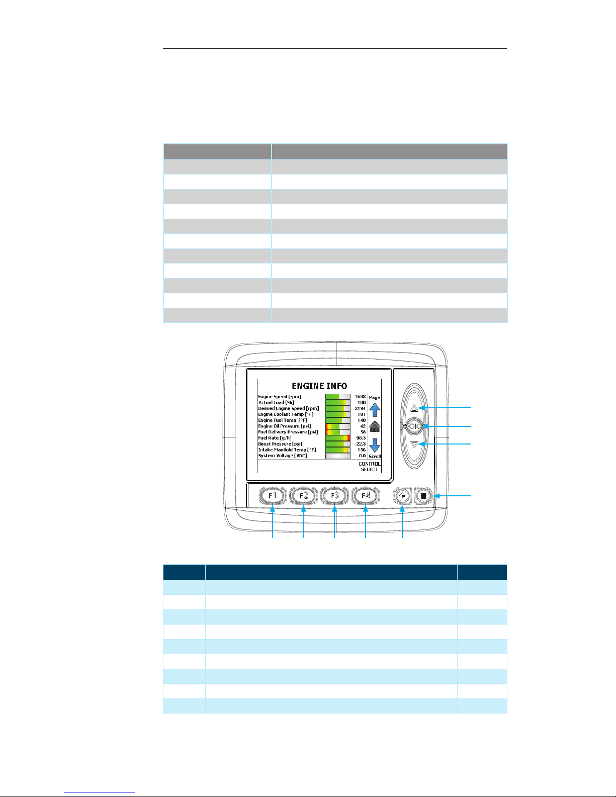
Engine Information Page
This page displays information related to the Machine’s Engine. This information is
broadcast by the ECM.
Contained within this page:
Parameter Unit of Measure
Engine speed RPM
Actual load Percent
Desired Engine speed RPM
Engine coolant temp ° Fahrenheit
Engine fuel temp ° Fahrenheit
Engine oil pressure PSI
Fuel delivery pressure PSI
Fuel rate Gallons per Hour
Boost pressure PSI
Intake manifold temp ° Fahrenheit
System voltage VDC
1
2
3
4
56789
Display Module Navigation
Number Description Page
1 Up Arrow — Press to navigate to the “Feed Control” Page 13
2 OK Button — Press to return to the “Main Page” 11
3 Down Arrow — Press to return to the “Main Page” 11
4 Menu Button — Press to navigate to the “System Menu” 21
5 Escape Button — Press to return to the “Main Page” 11
6 F4 Button — Press to navigate to the “Control Select” Page 18
7 F3 Button — Not used on the current screen --
8 F2 Button — Not used on the current screen --
9 F1 Button — Not used on the current screen --
12
Operator’s Manual, Morbark Integrated Control System—Model 20 Chipper
Page 13
Display Module Display Pages
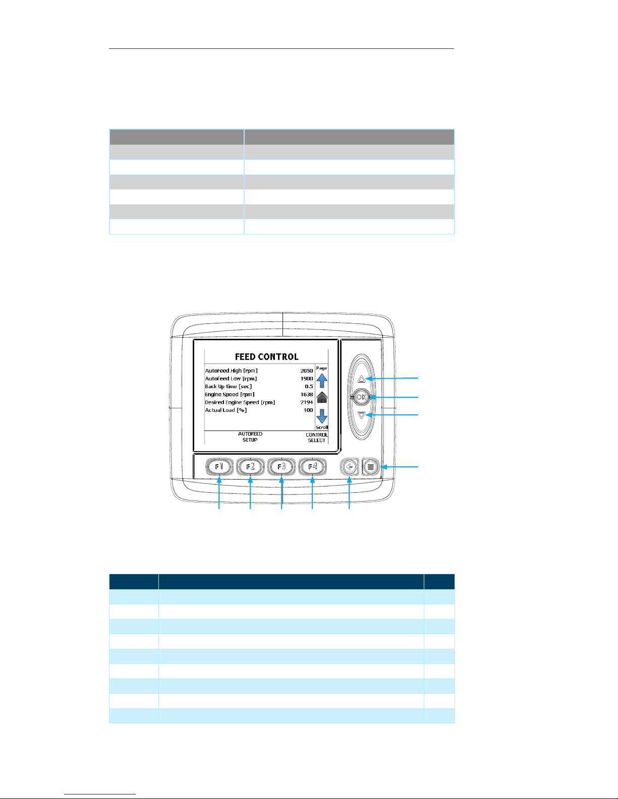
Feed Control Page
This page displays the parameters used to control the Machine’s feed system.
Contained within this page:
Parameter Unit of Measure
AutoFeed high setting RPM
AutoFeed low setting RPM
Backup time Seconds
Engine Speed RPM
Desired Engine Speed RPM
Actual Load Percent
1
2
3
4
56789
Display Module Navigation
Number Description Page
1 Up Arrow — Press to navigate to the “Control Information” Page 14
2 OK Button — Press to return to the “Main Page” 11
3 Down Arrow — Press to return to the “Engine Information” Page 12
4 Menu Button — Press to navigate to the “System Menu” 21
5 Escape Button — Press to return to the “Main Page” 11
6 F4 Button — Press to navigate to the “Control Select” Page 18
7 F3 Button — Not used on the current screen --
8 F2 Button — Press to navigate to the “Autofeed Setup“ option 17
9 F1 Button — Not used on the current screen --
Operator’s Manual, Morbark Integrated Control System—Model 20 Chipper
13
Page 14
Display Module Display Pages
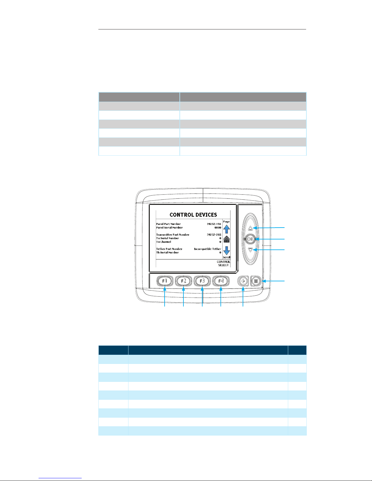
Control Devices Page
This page displays the Part Number, Serial Number and, if applicable, the Channel of
the various Control Devices for the Machine (Control Panel, Radio Transmitter, Tether
Remote.
Contained within this page:
Parameter Information Displayed
Panel Part Number Part Number of the Machine Control Panel
Panel Serial Number Serial number of the Machine Control Panel
Transmitter Part Number Part Number of the Radio Transmitter
Tx Serial Number Serial Number of the Radio Transmitter
Tether Part Number Part Number of the Tether Remote
Tether Serial Number Serial Number of the Tether Remote
1
2
3
4
56789
Display Module Navigation
Number Description Page
1 Up Arrow — Press to navigate to the “Main” Page 11
2 OK Button — Press to return to the “Main” Page 11
3 Down Arrow — Press to return to the “Feed Control” Page 13
4 Menu Button — Press to navigate to the “System Menu” 21
5 Escape Button — Press to return to the “Main Page” 11
6 F4 Button — Press to navigate to the “Control Select” Page 18
7 F3 Button — Not used on the current screen --
8 F2 Button — Not used on the current screen --
9 F1 Button — Not used on the current screen --
14
Operator’s Manual, Morbark Integrated Control System—Model 20 Chipper
Page 15

Performance Adjustment Pages
Performance Adjustment Pages
AutoFeed Settings Page 17
Control Select Page 18
Operator’s Manual, Morbark Integrated Control System—Model 20 Chipper
15
Page 16

Performance Adjustment Pages
Note: The “Performance
Adjustment Pages are protected
by a PIN N umber to pre vent unauthorize d access. In orde r to access
these settings:
Navigate to the “Adjust” SubMenu as desc ribed on page 25.
Use the “Up/Down” buttons to
navigate to the desired option
(only the “AutoFeed Set tings and
“Control Select” options are available to be modifi ed. All oth ers are
Pre-Set by the OEM).
Press the “OK” button. This will
bring up a dia log box for entry of
the PIN cod e
Use the “Up/Down” and OK buttons to enter the PIN code 0747.
The “OK” button must be p ressed
between each digit.
Afte r the last di git is ente red press
the “O K” button t wo(2) times , this
will open the desired adjustment
option.
Note: All modifications discussed
in this section can be reset to
“Factory Defaults” by pressing
the “F2” button from within the
option’s adjustment page.
Introduction
This section covers the different adjustment pages for the Machine. The parameters
contained within those pages will be provided along with a description and the values
each parameter accepts.
Contained within this section:
AutoFeed Settings — Used to modify the performance of the Machine’s feed
•
system
Control Select — Used to select the “Control Device” for the Machine•
16
Operator’s Manual, Morbark Integrated Control System—Model 20 Chipper
Page 17
Performance Adjustment Pages
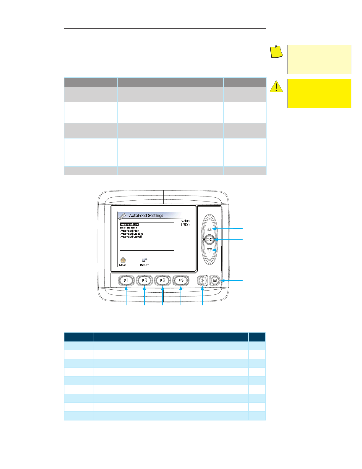
AutoFeed Settings Page
The settings on this page allow performance modification of the Machine’s feed system.
Contained within this page:
Parameter Description Unit of Measure
AutoFeed Low Setting The value that will cause the Machine to stop/
reverse feeding material into the mill.
Backup Time The length of time that the feed will reverse, allow-
ing the Engine to recover to performance level and
maintain consistent material output.
AutoFeed High Setting The value that will allow the Machine to start feed-
ing material into the mill.
AutoFeed Disable Setting at which the Machine AutoFeed will inhibit
the Feed System from reversing until the Engine
reaches the AutoFeed High Setting. This setting is
set below the AutoFeed Low Setting.
AutoFeed On/Off Toggle the AutoFeed option on and off On / Off
RPMs
Seconds (0-20)
RPMs
RPMs
Note: Setting the “AutoFeed
Low Setting” to a value above
the “AutoFeed High Setting” will
cause the Machine to not function properly.
Caution: Turning the AutoFeed
off could result in plugging the
mill and stalling the Engine. DO
SO AT YOUR OWN RISK.
1
2
3
4
56789
Display Module Navigation
Number Description Page
1 Up Arrow — Press to navigate through the list of options --
2 OK Button — Press to select the desired option --
3 Down Arrow — Press to navigate through the list of options --
4 Menu Button — Press to navigate to the previous “Display Page” --
5 Escape Button — Press to return to the “Main” menu screen 21
6 F4 Button — Not used on the current screen --
7 F3 Button — Not used on the current screen --
8 F2 Button — Press to reset all values to “Factory Default” --
9 F1 Button — Press to return to the “Main” menu screen 21
Operator’s Manual, Morbark Integrated Control System—Model 20 Chipper
17
Page 18
Performance Adjustment Pages
Control Select Page
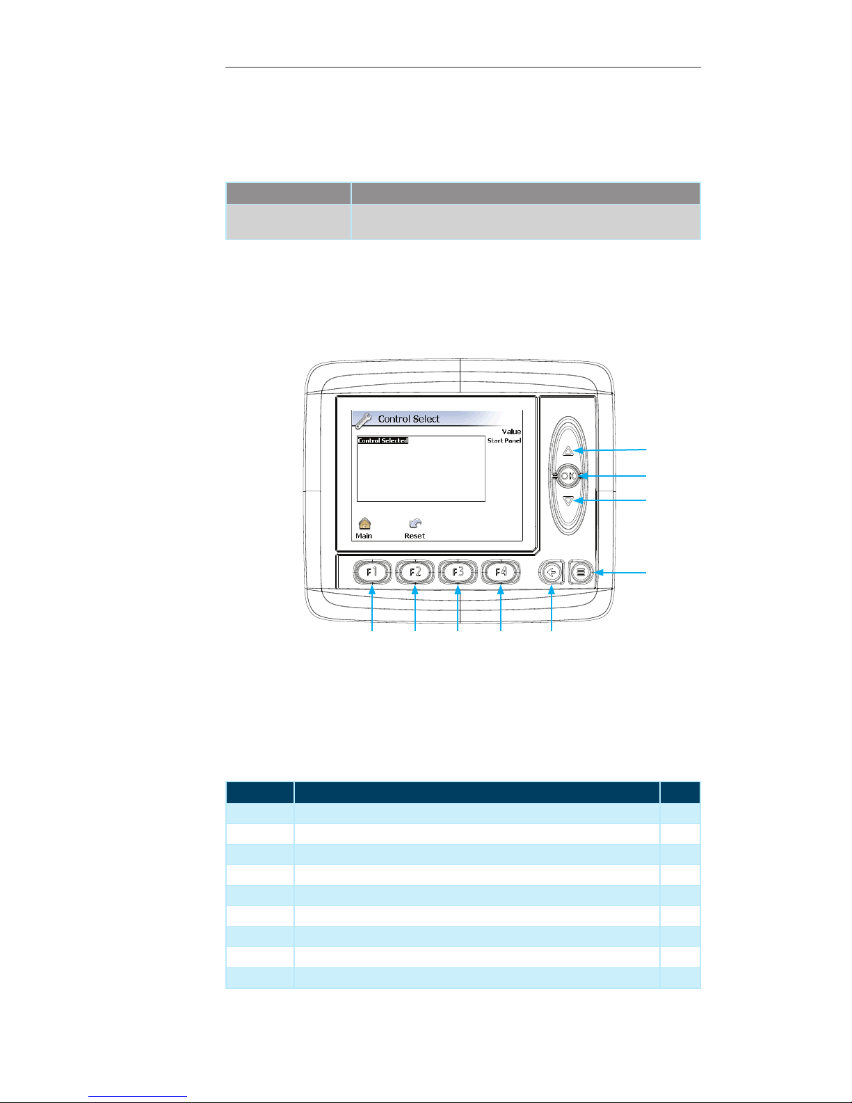
This page provides the ability to select the desired Control Device for the Machine.
Contained within this page:
Parameter Description
Control Selected This value specifies whether the system will run from the Control Panel,
Radio Remote or Tether Remote.
1
2
3
4
56789
Display Module Navigation
Number Description Page
1 Up Arrow — Press to navigate through the list of options --
2 OK Button — Press to select the desired option --
3 Down Arrow — Press to navigate through the list of options --
4 Menu Button — Press to navigate to the previous “Display Page” --
5 Escape Button — Press to return to the “Main” menu screen 21
6 F4 Button — Not used on the current screen --
7 F3 Button — Not used on the current screen --
8 F2 Button — Press to reset all values to “Factory Default” --
9 F1 Button — Press to return to the “Main” menu screen 21
18
Operator’s Manual, Morbark Integrated Control System—Model 20 Chipper
Page 19

Performance Adjustment Pages
Menu System
Accessing the Menu 21
Operator’s Manual, Morbark Integrated Control System—Model 20 Chipper
19
Page 20

Performance Adjustment Pages
Introduction
This section will discuss how to access and use the Display Module’s menu system to
obtain useful troubleshooting information and/or make performance adjustments to the
Machine.
Contained within this section:
Accessing the Menu System — Access the Menu System to make performance
•
adjustments to the Machine or adjust settings specific to the Display Module
20
Operator’s Manual, Morbark Integrated Control System—Model 20 Chipper
Page 21
Performance Adjustment Pages
Accessing the Menu
The menu system can be accessed at any time by simply pressing the “Menu” button
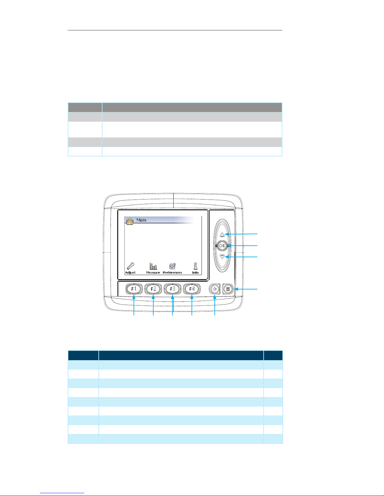
located in the lower right corner of the module. Once in the “Main” menu page the
“Function” buttons can be used to access the different sub-menus. These sub-menus
will be discussed in detail later in this section.
Contained within this page:
Menu Description
Adjust This menu provides access to the adjustable parameters for the Machine.
Measure This menu provides access the Machine’s “Measure Groups”. These allow measure-
ments of performance for certain aspects of the Machine.
Preferences This menu allows adjustment of the settings for the Display Module itself
Info This menu provides information related directly to the Machine
1
2
3
4
56789
Display Module Navigation
Number Description Page
1 Up Arrow — Not used on the current screen --
2 OK Button —Not used on the current screen --
3 Down Arrow — Not used on the current screen --
4 Menu Button — Press to return to previous “Display Page” --
5 Escape Button — Press to return to previous “Display Page” --
6 F4 Button — Press to navigate to the “Info” sub-menu 28
7 F3 Button — Press to navigate to the “Preferences” sub-menu 27
8 F2 Button — Press to navigate to the “Measure” sub-menu 26
9 F1 Button — Press to navigate to the “Adjust” sub-menu 25
Operator’s Manual, Morbark Integrated Control System—Model 20 Chipper
21
Page 22

Page 23

Performance Adjustment Pages
Sub-Menus
Adjust Menu 25
Measure 26
Preferences 27
Info 28
Operator’s Manual, Morbark Integrated Control System—Model 20 Chipper
23
Page 24

Note: To return to the “Main”
menu screen from within a submenu press the “F1” button.
Note: The “AutoFeed Settings”
Page requires a pin number to
access the settings. This number
is set to 0747. All other settings on
this page are Pre-Set at the factory and adjustable by the OEM
onl y.
Performance Adjustment Pages
Introduction
The sub-menus provide access to a variety of information about the Machine. This section will explain each of them in detail.
Contained in this section:
Adjust Menu — Provides access to the various adjustable settings on the Machine •
Measure Menu — Provides the ability to measure the performance of various
•
parameters on the Machine.
Preferences Menu — Allows modification of settings specific to the Display
•
Module
Info Menu — Provides quick access to information about the Machine•
24
Operator’s Manual, Morbark Integrated Control System—Model 20 Chipper
Page 25
Performance Adjustment Pages
Adjust Menu
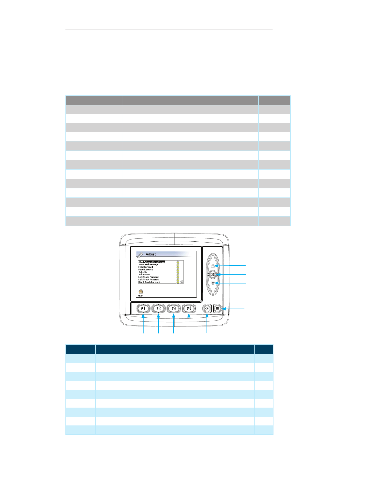
This page provides access to the various adjustable settings on the Machine. To access
the “Adjust” menu:
Press the “F1” button while on the “Main” menu page. 1.
Contained within this page:
Option Description Page No.
OEM Adjustable Settings These settings are pre-set from the factory.
AutoFeed Settings Settings related to the AutoFeed functionality of the Machine Page 17
Feed Forward These settings are pre-set from the factory.
Feed Reverse
Yoke Up
Yoke Down
Left Track Forward
Left Track Reverse
Right Track Forward
Right Track Reverse
Tx Joystick Deadband
Th Joystick Deadband
Control Select Settings Related to the Control Device(s) for the Machine Page 18
These settings are pre-set from the factory.
These settings are pre-set from the factory.
These settings are pre-set from the factory.
These settings are pre-set from the factory.
These settings are pre-set from the factory.
These settings are pre-set from the factory.
These settings are pre-set from the factory.
These settings are pre-set from the factory.
These settings are pre-set from the factory.
1
2
3
4
5
Display Module Navigation
8
9
6
7
Number Description Page
1 Up Arrow — Press to navigate parameters / increase parameter value --
2 OK Button — Press to select desired parameter / set new parameter value --
3 Down Arrow — Press to navigate parameters / decrease parameter value --
4 Menu Button — Press to return to previous “Display Page” --
5 Escape Button — Press to return to the “Main” menu page 21
6 F4 Button — Not used on the current screen --
7 F3 Button — Not used on the current screen --
8 F2 Button — Not used on the current screen --
9 F1 Button — Press to return to the “Main” menu page 21
Operator’s Manual, Morbark Integrated Control System—Model 20 Chipper
25
Page 26
Performance Adjustment Pages
Measure
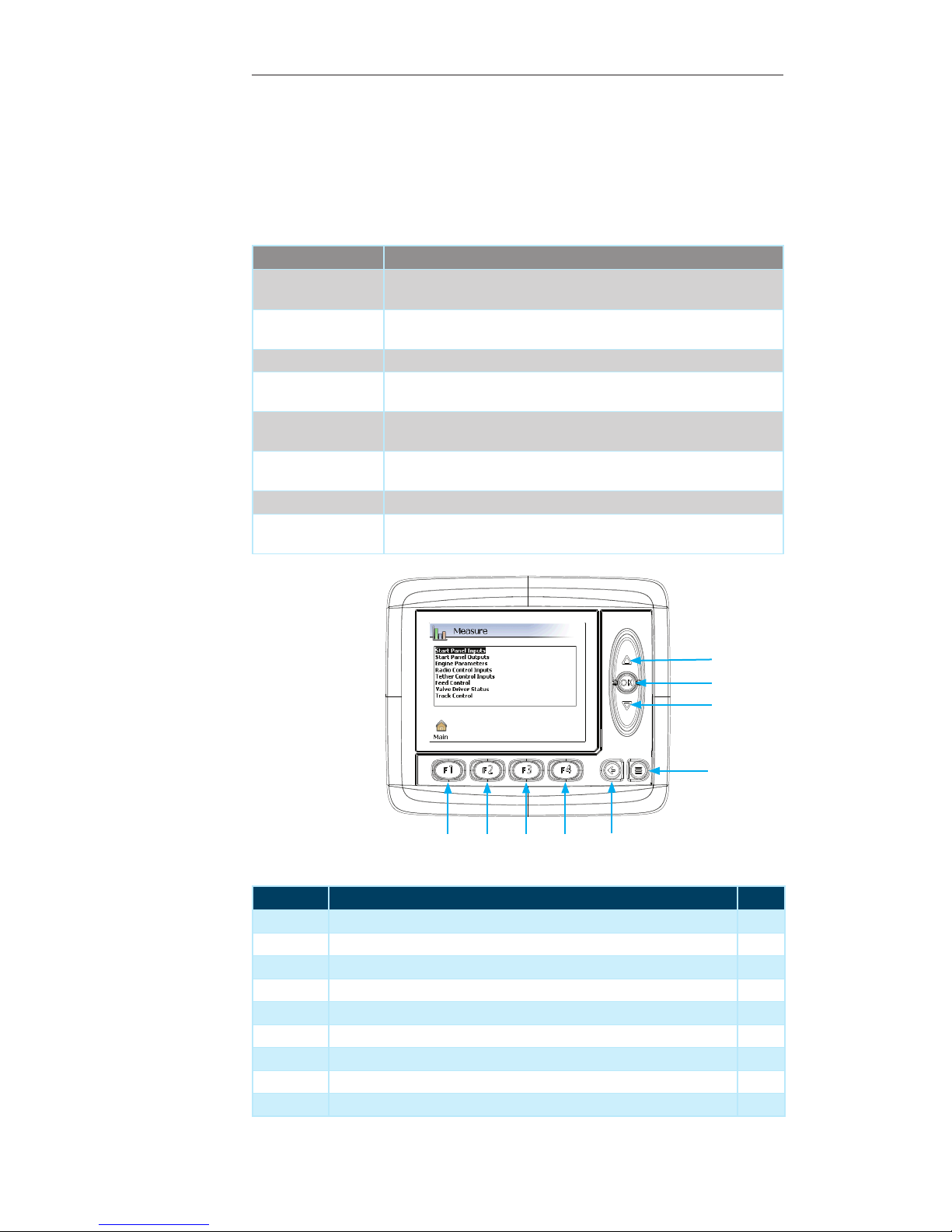
This page provides the ability to measure the performance of various parameters on the
Machine. To access the “Measure” menu:
Press the “F2” button while on the “Main” menu page.1.
Contained within this page:
Measure Group Description
Start Panel Inputs Provides information about the inputs coming from the Start Panel to the
Machine
Start Panel Outputs Provides information on the status of the various outputs coming from the
panel to the Machine
Engine Parameters Provides information about the status of the different Engine parameters
Radio Control Inputs Provides information about the various inputs coming from the Radio
Control to the Machine
Tether Remote Inputs Provides information about the various inputs coming from the Tether
Remote to the Machine
Feed Control Provides information on the status of the various aspects of the Machine’s
Feed System
Valve Driver Status Provides information on the status of the Valve Driver
Track Control Provides information on the status of the various Machine Track Control
Functions
1
2
3
4
5
8
9
6
7
Display Module Navigation
Number Description Page
1 Up Arrow — Press to navigate through the list of measure groups --
2 OK Button — Press to select the desired measure group --
3 Down Arrow — Press to navigate through the list of measure groups --
4 Menu Button — Press to return to previous “Display Page” --
5 Escape Button — Press to return to the “Main” menu page 21
6 F4 Button — Not used on the current screen --
7 F3 Button — Not used on the current screen --
8 F2 Button — Not used on the current screen --
9 F1 Button — Press to navigate to the “Main” menu page 21
26
Operator’s Manual, Morbark Integrated Control System—Model 20 Chipper
Page 27
Performance Adjustment Pages
Preferences
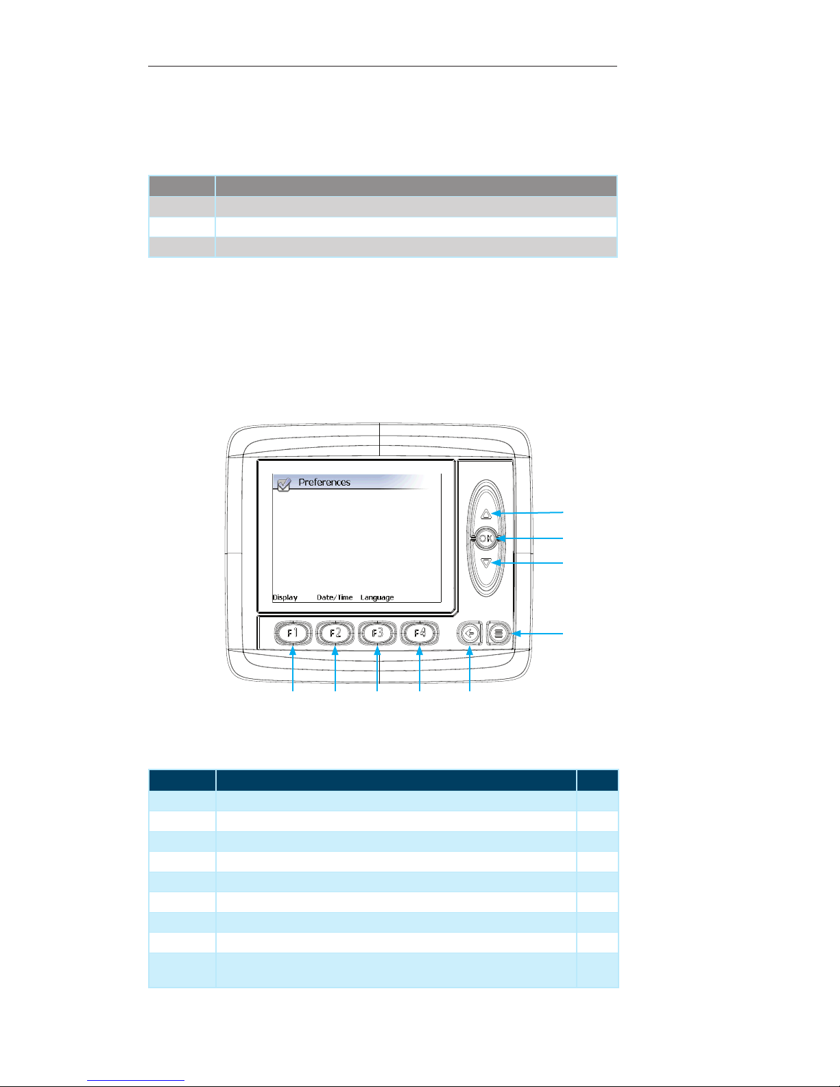
The “Preferences” menu allows modification of settings specific to the Display Module.
Contained within this page:
Option Description
Display Modify the intensity of the Backlight and toggle the Screensaver on or off
Date/Time Modify the Date and Time of the system
Language Change the Language option for the display
1
2
3
4
56789
Display Module Navigation
Number Description Page
1 Up Arrow — Not used on the current screen --
2 OK Button — Not used on the current screen --
3 Down Arrow — Not used on the current screen --
4 Menu Button — Press to return to previous “Display Page” --
5 Escape Button — Press to return to the “Main” menu page 21
6 F4 Button — Not used on the current screen --
7 F3 Button — Press to set the “Language” for the Display Module system --
8 F2 Button — Press to set the “Date/Time” for the Display Module system --
9 F1 Button — Press to adjust the “Display” settings for the Display Module
system
--
Operator’s Manual, Morbark Integrated Control System—Model 20 Chipper
27
Page 28
Performance Adjustment Pages
Info
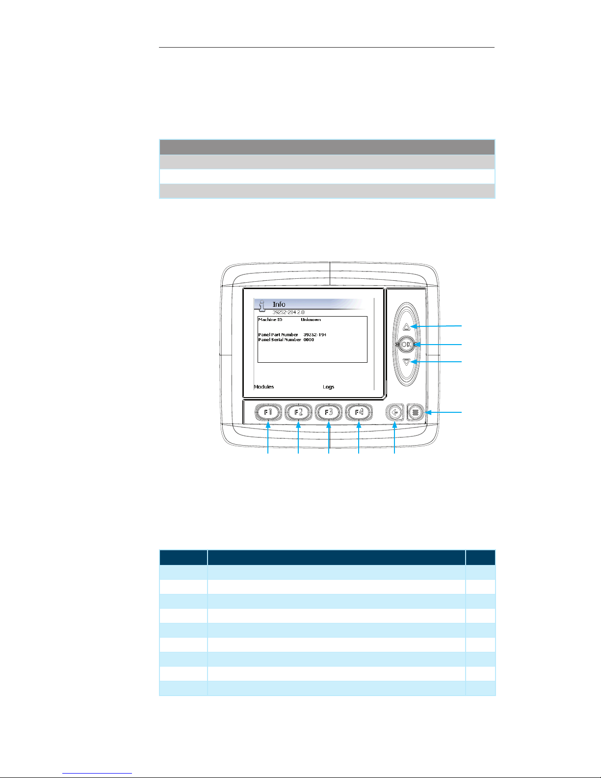
The “Info” menu provides quick access to information about the Machine. It also provides access to the status of all modules connected to the Machine.
Contained within this page:
Parameter
Machine ID
Machine Serial Number
Engine Serial Number
1
2
3
4
56789
Display Module Navigation
Number Description Page
1 Up Arrow — Not used on the current screen --
2 OK Button — Not used on the current screen --
3 Down Arrow — Not used on the current screen --
4 Menu Button — Press to return to previous “Display Page” --
5 Escape Button — Press to return to the “Main” menu page 21
6 F4 Button — Not used on the current screen --
7 F3 Button — Press to view the “Logs” for the Machine 29
8 F2 Button — Not used on the current screen --
9 F1 Button — Press to display the “Module Info” page 29
28
Operator’s Manual, Morbark Integrated Control System—Model 20 Chipper
Page 29

Performance Adjustment Pages
Pressing the “F1” button will display the “Modules” information page. This page displays the status of the various modules connected to the Machine.
Contained within this page:
Module
MD3 (Start Panel)
Engine ECM
LOR Receiver
J1939 Keypad
LOR Tether
Pressing the “F3” button will display the various logs or error events that are stored on
the system.
Press the “Up / Down” buttons to navigate through the logs. 1.
Press the “OK” button to view the log. 2.
While viewing a log:
Press the “F2” button to change the “Sort order” of the logs1.
Press the “F3” button to toggle the display of the date and time2.
Press the “F4” button to toggle between showing individual lines or pages. 3.
Contained within this page:
Log File
System Log
Engine Log
Operator’s Manual, Morbark Integrated Control System—Model 20 Chipper
29
Page 30

Page 31

Performance Adjustment Pages
Troubleshooting
This control system was designed to help interactively troubleshoot any issues that may
arise. To that end, anytime an issue occurs a detailed message will be displayed on
the Display Module’s screen. WRITE THESE MESSAGES AND THE SYSTEM
PART NUMBER(S)/SERIAL NUMBER(S) DOWN BEFORE CONTACTING A
SERVICE R EPRESENTATIVE. This information will be vital in helping diagnose
issues on the Machine.
Operator’s Manual, Morbark Integrated Control System—Model 20 Chipper
31
Page 32

For service for your Machine contact your Morbark Representative. Information in this manual is subject to change without notice
Publication — LMIP_MAN_M20C_100303_US
Version 1.0 March 2010
Ph: 800.233.6065
www.morbark.com
 Loading...