

G3 CCD Camera
User's Guide

Version 3.3
Modified on April 3rd, 2018
All information furnished by Moravian Instruments is believed to be
accurate. Moravian Instruments reserves the right to change any information
contained herein without notice.
G3 CCD cameras are not authorized for and should not be used within Life
Support Systems without the specific written consent of the Moravian
Instruments. Product warranty is limited to repair or replacement of
defective components and does not cover injury or property or other
consequential damages.
Copyright © 2000-2018, Moravian Instruments
Moravian Instruments
Masarykova 1148
763 02 Zlín
Czech Republic
tel./fax: +420 577 107 171
www: http://www.gxccd.com/
e-mail: info@gxccd.com

Table of Contents
Introduction...............................................................................................4
G3 Camera Overview...............................................................................6
CCD and Camera Electronics...................................................................9
CCD Chip..........................................................................................12
Model G3-1000...........................................................................12
Model G3-6300...........................................................................13
Model G3-11000.........................................................................13
Model G3-11000C.......................................................................13
Model G3-16200.........................................................................14
Model G3-16200C.......................................................................14
Camera Electronics...........................................................................14
Model G3-1000...........................................................................15
Model G3-6300...........................................................................15
Model G3-11000.........................................................................15
Model G3-16200.........................................................................16
Cooling and power supply......................................................................17
Power Supply....................................................................................18
Mechanical Specifications......................................................................20
Camera head dimensions..................................................................21
Telescope adapters............................................................................27
Off-Axis Guider Adapter (OAG)......................................................29
Attaching camera head to telescope mount.......................................30
Camera head color variants...............................................................31
Camera Maintenance..............................................................................32
Desiccant exchange...........................................................................32
Changing the silica-gel................................................................33
Changing Filters................................................................................35
Changing the Whole Filter Wheel....................................................37
Changing the Telescope Adapter......................................................37
Power Supply Fuse............................................................................38

Introduction
Thank you for choosing the Moravian Instruments CCD camera. G3 series of
CCD cameras were developed for imaging under extremely low-light
conditions in astronomy, microscopy and similar areas. Design of this series
inherits from G2 cameras, with which they share precise electronics providing
uniform frames without artifacts and extremely low read noise limited only by
CCD detector itself. Also the robust construction, rich software support and
easy manipulation are the same. However, G3 camera head is large enough to
contain detector up to 24×36 mm.
G3 cameras can contain also filter wheel with 5 positions for 2 inch (50 mm)
diameter filters.
G3 cameras can be equipped with external filter wheel, but it is not possible to
combine internal and external wheels on single camera. G3 camera mus be
made without internal filter wheel to be compatible with external filter wheels.
The G3 cameras are designed to work in cooperation with a host Personal
Computer (PC). As opposite to digital still cameras, which are operated
independently on the computer, the scientific slow-scan, cooled cameras
usually require computer for operation control, image download, processing
and storage etc. To operate the camera, you need a computer which:
1. Is compatible with a PC standard.
2. Runs a modern 32 or 64-bit Windows operating system.
Drivers for 32-bit and 64-bit Linux systems are also provided, but
camera control and image processing software, supplied with the
camera, requires Windows operating system.
3. Provides at last one free USB port.
G3 and G4 cameras are designed to operate with USB 2.0 high-speed
(480 Mbps) hosts. Although they are fully backward compatible with
USB 1.1 full-speed (12 Mbps) hosts, image download time can be
somewhat longer if USB 1.1 connection is used.
4

A simple and cheap device called USB hub can expand number of
available USB port. Typical USB hub occupies one computer USB
port and offers four free ports. Make sure the USB hub is USB 2.0
high-speed compatible.
But keep on mind that if more USB devices connected to one hub need
to communicate with a host PC, USB hub shares its single up link line
to the host PC. Although G3 and G4 cameras can operate through a
USB hub, it can negatively affect the camera performance, like
download time etc. It is recommended to connect other USB devices
through USB hub (e.g. the mouse) and to provide the camera a direct
USB connection to the host PC.
4. Alternatively it is possible to use the Gx Camera Ethernet Adapter.
This device can connect up to four Gx cameras of any type (not only
G3, but also G0, G1, G2 and G4) and offers 1 Gbps and 10/100 Mbps
Ethernet interface for direct connection to the host PC. Because the PC
then uses TCP/IP protocol to communicate with the cameras, it is
possible to insert e.g. WiFi bridge or other networking device to the
communication path.
The G3 cameras need an external power supply to operate. It is not possible to
run the camera from the power lines provided by the USB cable, which is
common for webcams or very simple imagers. G3 cameras integrate highly
efficient CCD chip cooling, shutter and possibly filter wheel, so their power
requirements significantly exceed USB line power capabilities. On the other
side separate power source eliminates problems with voltage drop on long USB
cables or with drawing of laptop batteries etc.
Also note the camera must be connected to some optical system (e.g. the
telescope) to capture images. The camera is designed for long exposures,
necessary to acquire the light from faint objects. If you plan to use the camera
with the telescope, make sure the whole telescope/mount setup is capable to
track the target object smoothly during the exposure.
5

G3 Camera Overview
G3 camera head is designed to be easily used with a set of accessories to fulfill
various observing needs. Camera head itself is manufactured in two different
variants:
● Camera with internal filter wheel with 5 positions for 2” or D50 mm
filters.
● Camera with control port for external filter wheel. This model allows
attachment of an external filter wheels with with 7 positions for 2” or
D50 mm filters.
The whole system comprises of various telescope adapters, which can be
attached to all variants of camera heads – without filter wheel, with internal
filter wheel or with external filter wheel.
Let us note that it is not possible to combine both internal and external filter
wheels. The external filter wheel reuses the control electronics, which stays idle
if the camera is not equipped with internal filter wheel. This solution eliminates
separate power and control cables for the external filter wheel, as it is attached
to the camera head. It also brings full software compatibility, as the software
does not distinguishes internal and external filter wheels, only the number of
available filters is different.
All telescope adapters, which preserve defined back focal distance (BFD –
typically bayonet adapters for photographic lenses but also the OAG adapter),
are designed for the external filter wheel BFD. If they are used on the camera
with internal filter wheel or without a filter wheel at all, it is necessary to use
spacers. Thin spacer compensates BFD difference between external and
internal filter wheel and thick spacer adds the thickness of the external filter
wheel housing to keep the BFD on camera without filter wheel.
6

Illustration 1: Schematic diagram of the G3 camera system components
7

Components of G3 Camera system include:
1. G3 camera head with internal filter wheel
2. G3 camera head capable to control External Filter Wheel
3. External Filter Wheel “S” size (7 positions)
4. External Filter Wheel “L” size (9 or 7 positions)
5. G0 Guider camera
6. G1 Guider camera
7. Off-Axis Guider with M68×1 thread
8. Spacer compensating IFW and EFW back focal distance
9. 1.75” dovetail rail for G3 camera head
10. Gx Camera Ethernet Adapter (x86 CPU)
11. Gx Camera Ethernet Adapter (ARM CPU)
Camera Ethernet Adapter allows connection of up to 4 Gx cameras of
any type on the one side and 1 Gbps Ethernet on the other side. This
adapter allows access to connected Gx cameras using routable TCP/IP
protocol over practically unlimited distance.
12. 5-positions internal filter wheel for 2”/D50 mm filters
13. 7-positions external filter wheel “S” for 2”/D50 mm filters
14. 9-positions external filter wheel “L” for 2”/D50 mm filters
15. 7-positions external filter wheel “L” for 50×50 mm filters
16. 2-inch barrel adapter
17. T-thread (M42×0.75) adapter
18. Canon EOS bayonet adapter for Canon compatible lenses
19. Nikon bayonet adapter for Nikon compatible lenses
8
CCD and Camera Electronics
G3 series of CCD cameras are manufactured with two kinds of OnSemi
(formerly Kodak) CCD detectors:
● G3 cameras with OnSemi KAF Full Frame (FF) CCD
architecture. Almost all Full Frame CCD detector area is exposed to
light. This is why these detectors provide very high quantum
efficiency. FF CCD detectors, intended for research applications, are
not equipped with so-called Anti Blooming Gate (ABG – a gate,
which prohibits blooming of the charge to neighboring pixels when
image is over-exposed) to ensure linear response to light. FF CCD
detectors used for astrophotography are equipped with ABG to
eliminate disrupting blooming streaks within field of view.
Cameras with Full Frame detectors are suitable for scientific
applications, where linear response is necessary for photometric
applications in astronomy, microscopy etc. High quantum efficiency
could be used also for narrow-band imaging, where overexposure is a
rare exception, and for imaging of small objects without a bright star
in the field of view.
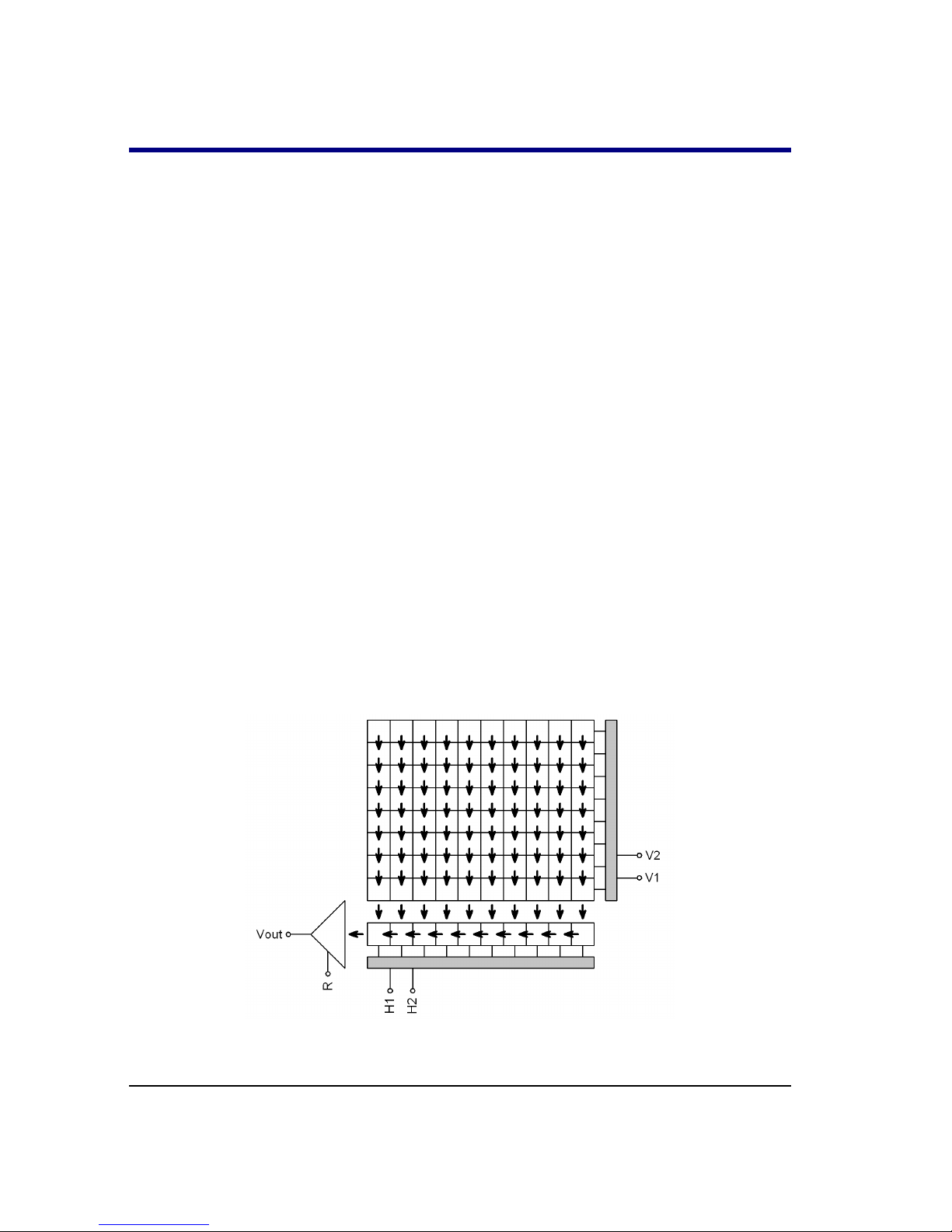
Illustration 2: “Full Frame” CCD schematic diagram
9

● G3 cameras with OnSemi KAI Interline Transfer (IT)
architecture. There is a shielded column of pixels just beside each
column of active pixels on these detectors. The shielded columns are
called Vertical registers. One pulse moves charge from exposed pixels
to shielded pixels on the end of each exposure. The the charge is
moved from vertical registers to horizontal register and digitized in
the same way like in the case of Full Frame detectors. This mechanism
is also known as “electronic shuttering”, because it allows very short
exposures and also digitization of the image without mechanically
shielding of the detector from incoming light.
Also cameras with IT CCDs are equipped with mechanical shutter,
because electronic shutter does not allow dark-frame exposures,
necessary for proper image calibration etc.
The price for electronic shutter if lower quantum efficiency
(sensitivity) of IT detectors compared to FF ones. Also all IT detectors
are equipped with ABG, so they can acquire images of very bright
objects without charge blooming to neighboring pixels.
10
Illustration 3: “Interline Transfer” CCD schematic diagram

G3 camera models with FF CCD architecture:
Model G3-1000 G3-6300 G3-16200 G3-16200C
CCD chip KAF-1001E KAF-6303E KAF-16200 KAF-16200
Resolution 1024×1024 3072×2048 4540×3640 4540×3640
Pixel size 24×24 μm 9×9 μm 6×6 μm 6×6 μm
CCD area 24.6×24.6 mm 27.7×18.4 mm 27.2×21.8 mm 27.2×21.8 mm
ABG No No Yes Yes
Color mask No No No Yes
G3 camera models with IT CCD architecture:
Model G3-11000 G3-11000C
CCD chip KAI-11002 KAI-11002
Resolution 4032×2688 4032×2688
Pixel size 9×9 μm 9×9 μm
CCD area 36.3×24.2 mm 36.3×24.2 mm
ABG Yes Yes
Color mask No Yes
Cameras with “C” suffix contains CCD detector covered with so-called Bayer
mask. Color filters of three basic colors (red, green, blue) cover all pixels, so
every pixels detects only light of particular color.
11

These cameras are able to acquire color image in single exposure, without the
necessity to change color filters. On the other side color mask brings lower
sensitivity and limits the capability to perform exposures using narrow-band
filters etc.
Because each pixel is covered by one of three basic color filters, it is necessary
to compute (interpolate) remaining two colors for each pixel, which of course
limits resolution of color image. Imaging using color detectors is described in
the “Color images” chapter.
CCD Chip
Quantum efficiency (sensitivity) of CCD detectors used in G3 cameras depends
on the particular camera model.
Illustration 4: Quantum efficiency of CCD detectors used in G3
Inherent dark current of these detectors is quite low compared to other CCD
detectors, suitable for scientific applications, which results into very good
signal/noise ratio.
Model G3-1000
G3-1000 model uses 1 MPx OnSemi KAF-1001E Class 1 or 2 CCD chip.
Resolution 1024×1024 pixels
12

Pixel size
24×24 μm
Imaging area 24.6×24.6 mm
Full well capacity Approx. 220 000 e-
Output node capacity Approx. 650 000 e-
Dark current 17 e-/s/pixel at 0°C
Dark signal doubling 5.5 °C
Model G3-6300
G3-6300 model uses 6 MPx OnSemi KAF-6303E Standard Class CCD chip.
Resolution 3072×2048 pixels
Pixel size
9×9 μm
Imaging area 27.7×18.4 mm
Full well capacity Approx. 100 000 e-
Output node capacity Approx. 220 000 e-
Dark current 1 e-/s/pixel at 0°C
Dark signal doubling 6.3 °C
Model G3-11000
G3-11000 uses 11 MPx CCD OnSemi KAI-11002 Class 1 or 2.
Resolution 4032×2688 pixels
Pixel size 9×9 μm
Imaging area 36,3×24,2 mm
Full well capacity Approx. 60 000 e-
Dark current 12 e-/s/pixel at 0°C
Dark signal doubling 7 °C
ABG >1000×
Model G3-11000C
G3-11000C uses 11 MPx CCD OnSemi KAI-11002 Class 1 or 2 with color
(Bayer) mask.
13

Model G3-16200
G3-16200 uses 16 MPx CCD OnSemi KAF-16200.
Resolution 4540×3640 pixels
Pixel size 6×6 μm
Imaging area 27.2×21.8 mm
Full well capacity approx. 41 000 e-
Dark current 0,08 e-/s/pixel at 0°C
Dark signal doubling 5.7 °C
ABG 2800×
Model G3-16200C
G3-16200C uses 16 MPx CCD OnSemi KAF-16200 with color (Bayer) mask.
Camera Electronics
16-bit A/D converter with correlated double sampling ensures high dynamic
range and CCD chip-limited readout noise. Fast USB interface ensures image
download time within seconds.
Maximum length of single USB cable is 5 m. This length can be extended to
10 m by using single USB hub or active USB extender cable. Up to 5 hubs or
active extenders can be used in one connection.
Gx Camera Ethernet Adapter device allows connection of up to four Gx
cameras of any type through Ethernet interface and TCP/IP network. Because
TCP/IP protocol can be routed, the distance between camera and host PC can
be virtually unlimited.
ADC resolution 16 bits
Sampling method Correlated double sampling
Read modes Preview
Low-noise
Horizontal binning 1 to 4 pixels
Vertical binning 1 to 4 pixels
14

Sub-frame readout Arbitrary sub-frame
Computer interface USB 2.0 high-speed
USB 1.1 full-speed compatible
Binning can be combined independently on both axes.
Image download time and system read noise depends on the CCD chip used in
particular camera model.
Model G3-1000
Gain 3 e-/ADU (1×1 binning)
5 e-/ADU (other binnings)
System read noise 12 e- (Low noise)
15 e- (Preview)
Full frame download 1.6 s (Low noise)
1.3 s (Preview)
Model G3-6300
Gain 1.5 e-/ADU (1×1 binning)
2.3 e-/ADU (other binnings)
System read noise 10 e- (Low noise)
12 e- (Preview)
Full frame download 9.4 s (Low noise)
7.3 s (Preview)
Model G3-11000
Gain 0.8 e-/ADU (1×1 binning)
1.6 e-/ADU (other binnings)
System read noise 11,5 e- (Low noise)
13 e- (Preview)
Full frame download 14.9 s (Low noise)
11.2 s (Preview)
15

Model G3-16200
Gain 0.6 e-/ADU (1×1 binning)
1.0 e-/ADU (other binnings)
System read noise 10 e- (Low noise)
11 e- (Preview)
Full frame download 24.5 s (Low noise)
18.8 s (Preview)
16

Cooling and power supply
Regulated two-stage thermoelectric cooling is capable to cool the CCD chip
from 45 to 50 °C below ambient temperature, depending on the camera type.
The Peltier hot side is cooled by a fans. The CCD chip temperature is regulated
with ±0.1 °C precision. High temperature drop and precision regulation ensure
very low dark current for long exposures and allow proper image calibration.
G3 cameras are available in two variants, differing in the cooling performance:
● Standard cooling cameras achieve temperature difference up to 45 °C
Under environment temperature.
● Enhanced cooling cameras can regulate temperature up to 50 °C
under environment temperature. Compared to standard variant,
enhanced cooling cameras are somewhat bulkier due to bigger heat
sink, slightly heavier and somewhat noisier because of more powerful
fans.
The camera head contains two temperature sensors – the first sensor measures
directly the temperature of the CCD chip. The second one measures the
temperature of the air cooling the Peltier hot side.
The cooling performance depends on the environmental conditions and also on
the power supply. If the power supply voltage drops below 12 V, the maximum
temperature drop is lower.
CCD chip cooling Thermoelectric (Peltier modules)
Standard cooling ΔT
48 °C below ambient maximum
45 °C below ambient typical
Enhanced cooling ΔT
53 °C below ambient maximum
50 °C below ambient typical
Regulation precision
±0.1 °C
Hot side cooling Forced air cooling (two fans)
Optional liquid coolant heat exchanger
17

Maximum temperature difference between CCD and ambient air may be
reached when the cooling runs at 100% power. However, temperature cannot
be regulated in such case, camera has no room for lowering the CCD
temperature when the ambient temperature rises. Typical temperature drop can
be achieved with cooling running at approx. 85% power, which provides
enough room for regulation.
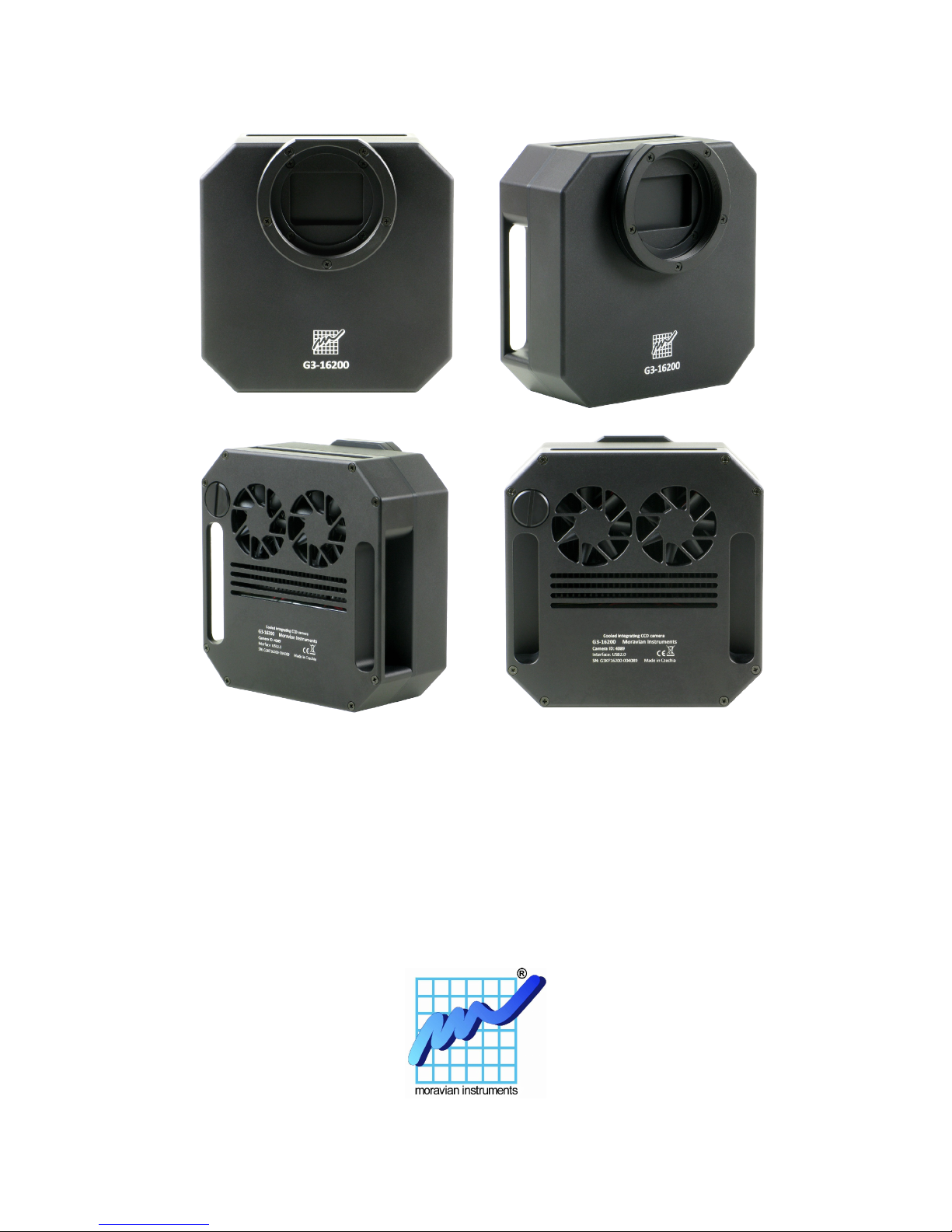
Illustration 5: Comparison of the standard (left) and enhanced (right) cooling cameras
Power Supply
The 12 V DC power supply enables camera operation from arbitrary power
source including batteries, wall adapters etc. Universal 100-240 V AC/5060 Hz, 60 W “brick” adapter is supplied with the camera. Although the camera
power consumption does not exceed 55 W, the 60 W power supply ensures
noise-free operation.
Camera head supply 12 V DC
Camera head power consumption 15 W without cooling
52 W maximum cooling
Power connector 5.5/2.5 mm, center +
Adapter input voltage 100-240 V AC/50-60 Hz
Adapter output voltage 12 V DC/5 A
Adapter maximum power 60 W
18
1. Power consumption is measured on the AC side of the supplied 12 V
AC/DC power supply. Camera consumes less energy from 12 V power
supply than state here.
2. The camera contains its own power supplies inside, so it can be
powered by unregulated 12 V DC power source – the input voltage
can be anywhere between 10 and 14 V. However, some parameters
(like cooling efficiency) can degrade if the supply drops below 12 V.
3. G3 camera measures its input voltage and provides it to the control
software. Input voltage is displayed in the Cooling tab of the Imaging
Camera control tool in the SIPS. This feature is important especially if
you power the camera from batteries.
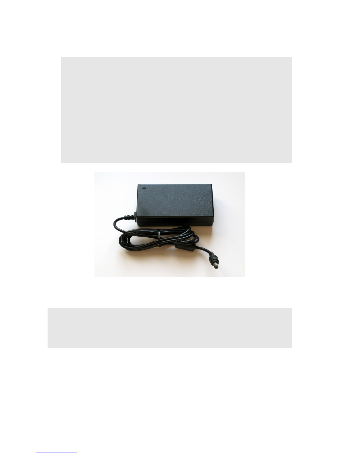
Illustration 6: 12 V DC/5 A power supply adapter for
G3 and G4 CCD Camera
Warning:
The power connector on the camera head uses center-plus pin. Although all
modern power supplies use this configuration, always make sure the polarity is
correct if you use own power source.
19

Mechanical Specifications
Compact and robust camera head measures only 154×154×65 mm (approx.
6×6×2.6 inches) for the model with standard cooling without internal filter
wheel. Enhanced cooling increases camera depth by 11 mm and internal filter
wheel adds another 12.5 mm. The head is CNC-machined from high-quality
aluminum and black anodized. The head itself contains USB-B (device)
connector and 12 V DC power plug, no other parts (CPU box, USB interface,
etc.), except a “brick” power supply, are necessary. Integrated mechanical
shutter allows streak-free image readout, as well as automatic dark frame
exposures, which are necessary for unattended, robotic setups. Integrated filter
wheel contains 5 positions for standard 2-inch filter cells with M48×0.75
thread. There are three M3 threaded holes around each filter position, which
allow fixing of filters without cells (only a glass) up to 51 mm diameter.
Mechanical shutter Yes, blade shutter
Shortest exposure time 0.2 s
Longest exposure time Limited by chip saturation only
Internal filter wheel
(optional)
5 positions 2" threaded filter cells or glass filters up to
51 mm diameter
Standard cooling head
dimensions
154×154×65 mm (G3 without filter wheel)
154×154×77.5 mm (G3 with internal filter wheel)
Enhanced cooling head
dimensions
154×154×76 mm (G3-EC without filter wheel)
154×154×88.5 mm (G3-EC with internal filter wheel)
Back focal distance 16,5 mm (G3 without filter wheel)
29 mm (G3 with internal filter wheel)
33.5 mm (G3 with external filter wheel)
Standard cooling head
weight
1.6 kg (G3 without filter wheel)
1.9 kg (G3 with internal filter wheel)
2.5 kg (G3 with “S” external filter wheel)
20

Enhanced cooling head
weight
1.8 kg (G3-EC without filter wheel)
2.1 kg (G3-EC with internal filter wheel)
2.7 kg (G3-EC with “S” external filter wheel)
Camera head dimensions
Illustration 7: G3 camera front view (both standard and enhanced cooling)
21
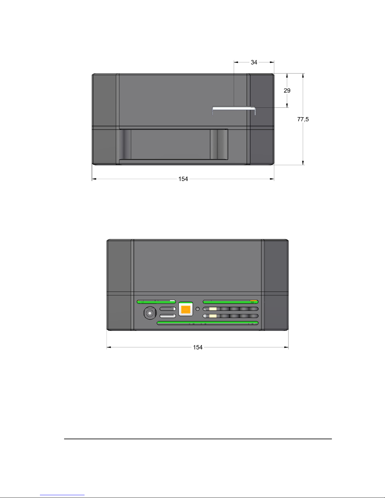
Illustration 8: G3 camera with standard cooling and internal filter wheel
side view
Illustration 9: G3 camera with standard cooling and internal
filter wheel bottom view
22

Illustration 10: G3 camera with enhanced cooling and internal filter wheel
side view
Illustration 11: G3 camera with enhanced cooling and internal
filter wheel bottom view
23
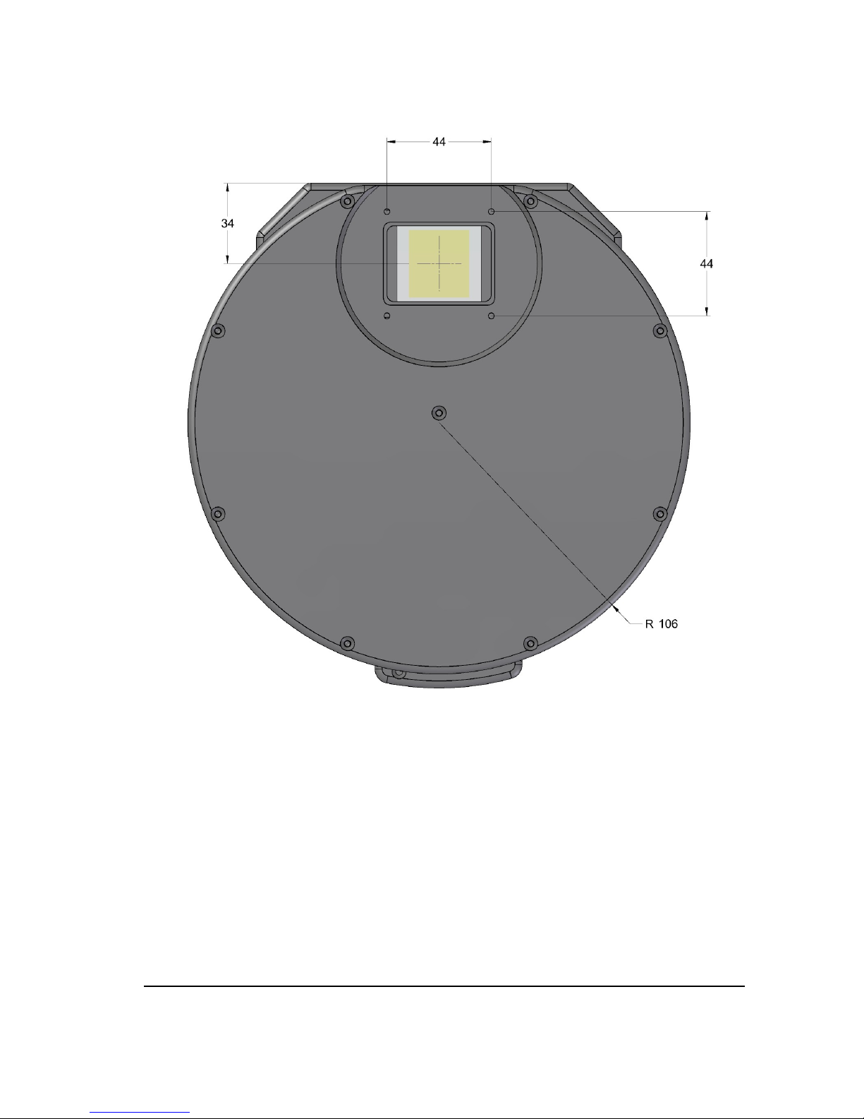
Illustration 12: G3 camera front view (both standard and enhanced cooling) with
“S” size external filter wheel
24
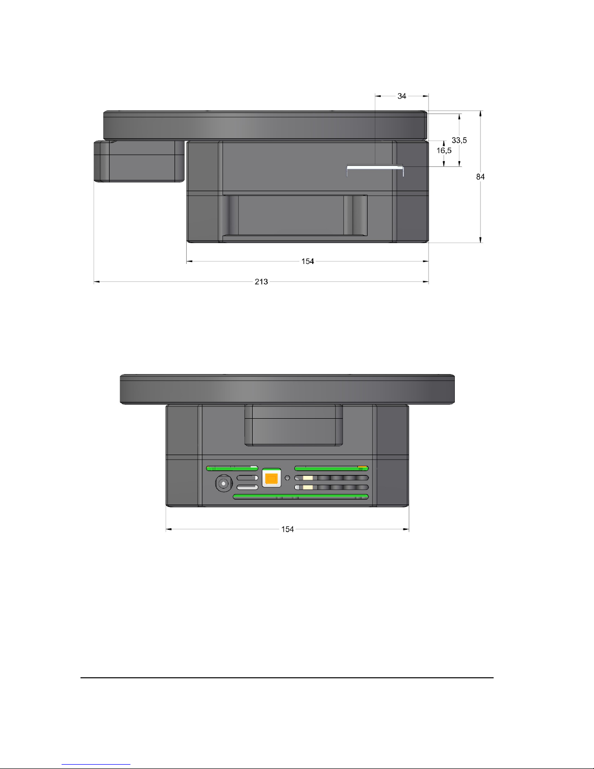
Illustration 13: G3 camera with standard cooling and “S” size external filter wheel side
view
Illustration 14: G3 camera with standard cooling and “S” size external filter
wheel bottom view
25

Illustration 15: G3 camera with enhanced cooling and “S” size external filter wheel
side view
Illustration 16: G3 camera with enhanced cooling and “S” size external
filter wheel bottom view
26

Telescope adapters
Various telescope and lens adapters for the G3 cameras are offered. Users can
choose any adapter according to their needs and another adapters can be
ordered separately.
It is possible to choose among various telescope/lens adapters:
2" barrel adapter Adapter for 2" focusers.
T-thread short
M42×0.75 mm inner thread,
7.5 mm thick.
T-thread with
55 mm BFD
M42×0.75 mm inner thread,
preserves 55 mm back focal
distance.
M48×0.75 thread
short
Adapter with inner thread
M48×0.75, 7.5mm thick
M48×0.75 thread
with 55 mm BFD
Adapter with inner thread
M48×0.75, preserves
55 mm back focal distance.
Pentax (Praktica)
lens adapter
M42×1 mm inner thread,
preserves 45.5 mm back
focal distance.
27

M68×1 thread
adapter
Adapter with inner thread
M68×1.
Canon EOS lens
adapter
Standard Canon EOS
bayonet adapter.
Canon EOS clip lens
adapter
Canon EOS bayonet adapter
with the possibility to insert
“clip” filter. Can be used on
cameras with internal filter
wheel only.
Nikon F lens
adapter
Standard Nikon F bayonet
adapter.
3” Wynne adapter Adapter for 3” coma-
corrector ASA Wynne.
3” Paracorr BIG
adapter
Adapter for 3” comacorrector TeleVue Paracorr
BIG, intended for G3-OAG.
3” Paracorr BIG
adapter
Adapter for 3” comacorrector TeleVue Paracorr
BIG, intended for attaching
to EFW with M68×1.
28

T-thread (M42×0.75) adapter or M42×1 adapter cause vignetting when used
with cameras equipped with large sensors. Also common coma correctors
(often equipped with T-thread) cause vignetting with this large chip. G3
cameras with 24×36 mm CCD require using of M68×1 adapter.
If the mounting standard defines also back focal distance (distance from adapter
front plane to detector), the particular adapter is constructed to preserve defined
distance (for instance T-thread defines back focal distance to 55 mm, but
certain distance is defined also for Pentax (Praktica) thread, for Canon EOS and
Nikon bayonets etc.).
Adapters are attached to the camera body using four M3 (3 mm metric) screws.
These threaded holes are placed on the corners of 44 mm square. Custom
adapters can be made upon request.
Off-Axis Guider Adapter (OAG)
G3 camera can be optionally equipped with Off-Axis Guider Adapter. This
adapter contains flat mirror, tilted by 45° to the optical axis. This mirror reflects
part of the incoming light into guider camera port. The mirror is located far
enough from the optical axis not to block light coming to the main camera
sensor, so the optics must be capable to create large enough field of view to
illuminate the tilted mirror.
Because of the above described reasons the G3-OAG is manufactured with
M68×1 threaded adapter. G3-OAG is compatible with external filter wheels.
Adapter back focal distance is 61.5 mm.
If the OAG has to be used on camera with internal filter wheel, it is necessary
to insert a spacer between OAG and camera head compensating BFD
difference. Similar, but thicker spacer must be used when OAG is mounted to
camera without filter wheel at all.
OAG guider port is compatible with G0 and G1 cameras. It is necessary to
replace the CS/1.25” adapter with short, 10 mm variant in the case of G1
cameras. Because G1 cameras follow CS-mount standard, (BFD 12.5 mm), any
camera following this standard with 10 mm long 1.25” adapter should work
properly with the G3-OAG.
29

Illustration 17: G3-OAG on the camera head
Attaching camera head to telescope mount
G3 cameras are equipped with two “tripod” 0.250-20UNC threads on the top
side of the camera head. This thread can be used to attach 1.75 inch “dovetail
bar” (Vixen standard). It is then possible to attach the camera head, e.g.
equipped with photographic lens, directly to various telescope mounts
supporting this standard.
Illustration 18: 1.75" bar for standard telescope mounts
30

Camera head color variants
Camera head is available in several color variants of the center plate. Visit
manufacturer's web pages for current offering.
Illustration 19: G3 camera color variants
31

Camera Maintenance
The G3 camera is a precision optical and mechanical instrument, so it should be
handled with care. Camera should be protected from moisture and dust. Always
cover the telescope adapter when the camera is removed from the telescope or
put the whole camera into protective plastic bag.
Desiccant exchange
The G3 camera cooling is designed to be resistant to humidity inside the CCD
chamber. When the temperature decreases, the copper cold finger crosses
freezing point earlier than the CCD chip itself, so the water vapor inside the
CCD chamber freezes on the cold finger surface first. Although this mechanism
works very reliably in majority of cases, it has some limitations, especially
when the humidity level inside the CCD chamber is high or the chip is cooled
to very low temperatures.
This is why a cylindrical container, filled with silica-gel desiccant, is placed
inside the camera head. This cylindrical chamber is attached to the insulated
cooled CCD chamber itself.
Warning:
High level of moisture in the CCD chip chamber can cause camera malfunction
or even damage to the CCD chip. Even if the frost does not create on the
detector when the CCD is cooled below freezing point, the moisture can be still
present. It is necessary to keep the CCD chamber interior dry by the regular
exchange of the silica-gel. The frequency of necessary silica-gel exchanges
depends on the camera usage. If the camera is used regularly, it is necessary to
dry the CCD chamber every few months.
It is possible dry the wet silica-gel by baking it in the oven (not the microwave
one!) to dry it again. Dry the silica-gel for at last one or two hours at
temperature between 120 and 140 °C.
The silica-gel used in G3 cameras changes its color according to amount of
water absorbed – it is bright yellow or orange when it is dry and turns to
32
transparent without any color hue when it becomes wet. It is recommended to
shorten replacement interval if the silica-gel is completely transparent upon
replacement. If it is still yellow-orange, it is possible to prolong the
replacement interval.
Note:
The silica-gel ability to absorb moisture depends on the ambient temperature. If
the camera is located in the environment with below freezing point
temperatures, drying of the CCD cold chamber can take up to several days.
Illustration 20: Silica-gel container is accessible from the camera back side
Changing the silica-gel
The desiccant container design depends on the camera revision:
● G3 cameras revision 1 have the container accessible from the back
side of the camera head. The slotted desiccant chamber cap can be
unscrewed e.g. by a coin. Pour out wet silica-gel and fill the chamber
with a dry one. The desiccant chamber can be filled with a hot silicagel without a danger of damaging of the container.
The desiccant container can be left open without the fear from
contamination of CCD chamber interior by dust. There is a very faint
stainless steel grid between the CCD chamber and the desiccant
container, so dust particles cannot enter the chamber itself. It is even
33

recommended to keep the desiccant container cap off for a couple of
hours when the camera is in the room with low humidity. This helps
drying the CCD chamber interior and prolongs the silica-gel exchange
interval.
● G3 revision 2 cameras cameras supplied in 2016 and later are
equipped with a redesigned desiccant containers. New containers are
no longer a fixed part of the camera body with only a removable cap,
but the whole container can be unscrewed. The main advantage of this
design is the ability to exchange silica-gel without the necessity to
remove the camera from the telescope, which was necessary to be able
to pour-out the silica-gel and then to pour it in.
Silica-gel is held inside the container with a perforated cap. This cap is
also screwed into the container body, so it is easy to exchange the
silica-gel inside the container after it is worn out or damaged e.g. by
too high temperature etc.
The container itself does not contain any sealing (the sealing remains
attached to the CCD cold chamber inside the camera head), it consists
of aluminum parts only. So it is possible to heat the whole container to
desired temperature without risking of the temperature-induced sealing
damage.
This design also allows usage of some optional parts. First it is a
threaded hermetic cap, which allows sealing of the dried container
when it is not immediately attached to the camera head. And the
second one is an alternate (somewhat longer) desiccant container,
modified to be able to be screw in and tightened (as well as released
and screwed out) without any tool.
The sealed cap as well as the tool-less container are not supplied with
the camera, the are supplied only as optional accessory.
● The G3 cameras with Enhanced Cooling are equipped with a bigger
heat sink and thus also thicker back shell. This requires usage of the
longer desiccant containers. Both container variants (the standard one
and also the tool-less variant) are supplied in two lengths. Shortened
containers for standard cameras and longer ones for Enhanced Cooling
cameras.
34
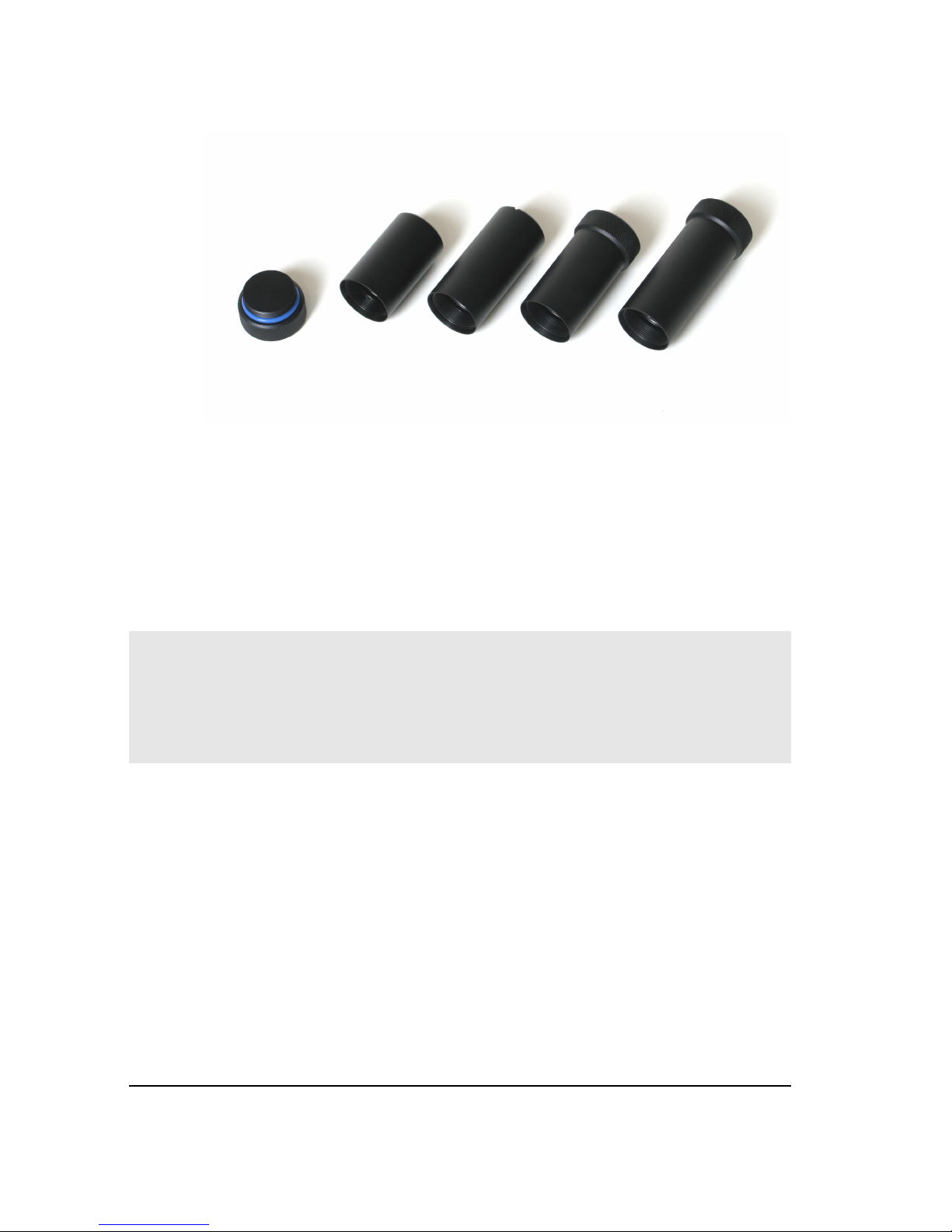
Illustration 21: Optional cap, containers with a slot and containers for toolless manipulation, versions for the standard and Enhanced Cooling cameras
Changing Filters
It is necessary to open the camera head to change filters or the whole filter
wheel of the G3 camera. Opening the head is quite simple – it is just necessary
to unscrew she eight bolts, which holds the camera head together.
Warning:
The blade shutter rotates 180° between individual snapshots. Camera cover
could be opened only when the shutter is closed. If for instance the camera is
unplugged from power adapter while exposing and the shutter remains open, it
can be damaged while removing the camera cover.
35
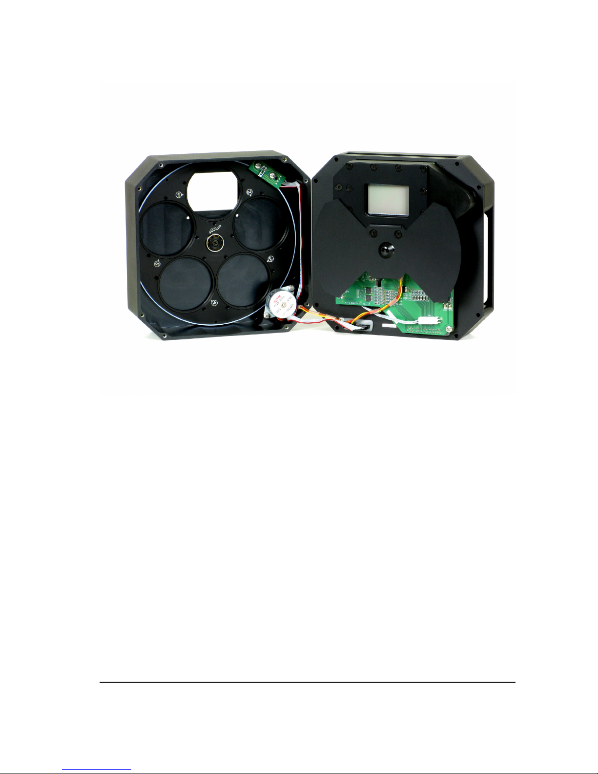
Illustration 22: Filters can be changed after opening the camera case front shell
After removing the screws carefully turn the camera head by the telescope
adapter upward. Gently pull the front part of the case. Notice there are two
cables, connecting the filter wheel motor and the filter position optical bar,
plugged into the electronics board. It is not necessary to unplug these cables to
change filters, but if you unplug them, take care to connect them again in the
proper orientation!
Filter numbering is always engraved into the wheel, as illustrated on the image
below.
36
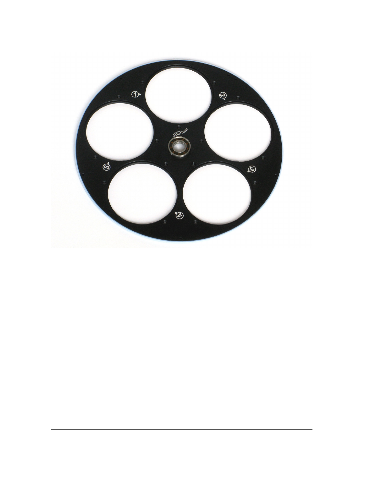
Illustration 23: Filter positions in the G3 filter wheel
Changing the Whole Filter Wheel
The whole filter wheel can be changed at once. It is necessary to remove the
front part of the camera case the same way as in the case of changing filters.
The filter wheel can be removed when you unscrew the bolt on the center of the
front part of camera case. Take care not to damage the horseshoe-shaped
optical bar when replacing the filter wheel.
Changing the Telescope Adapter
The camera head contains bolt square. The telescope adapter is attached by four
bolts. If you want to change the adapter, simply unscrew these bolts and replace
the adapter with the new one.
37

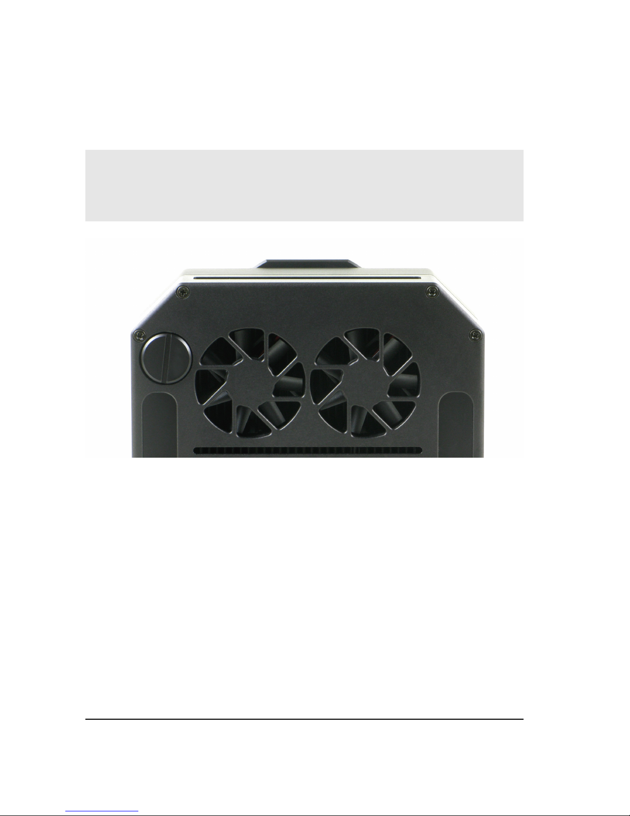
Power Supply Fuse
The power supply inside the camera is protected against connecting of invertedpolarity power plug or against connecting of too-high DC voltage (above 15 V)
by a fuse. If such event happens and the cooling fans on the back side of the
camera do not work when the camera is connected to proper power supply,
return the camera to the service center for repair.
38
 Loading...