

G0 and G1 CCD Camera
User's Guide

Version 3.0
Modified on December 15th, 2015
All information furnished by Moravian Instruments is believed to be
accurate. Moravian Instruments reserves the right to change any information
contained herein without notice.
G0 and G1 CCD devices are not authorized for and should not be used
within Life Support Systems without the specific written consent of the
Moravian Instruments. Product warranty is limited to repair or replacement
of defective components and does not cover injury or property or other
consequential damages.
Copyright © 2000-2015, Moravian Instruments
Moravian Instruments
Masarykova 1148
763 02 Zlín
Czech Republic
tel./fax: +420 577 107 171
internet: http://www.gcxxd.com/
e-mail: info@gxccd.com

Table of Contents
Introduction...............................................................................................4
Camera Technical Specifications.............................................................7
CCD Chip............................................................................................9
Model G0-0300 and G1-0300.......................................................9
Model G0-0300C and G1-0300C..................................................9
Model G1-0301...........................................................................10
Model G1-0301C.........................................................................10
Model G0-0800 and G1-0800.....................................................10
Model G0-0800C and G1-0800C................................................11
Model G0-2000 and G1-2000.....................................................11
Model G0-2000C and G1-2000C................................................11
Model G1-1200...........................................................................11
Model G1-1200C.........................................................................12
Model G1-1400...........................................................................12
Model G1-1400C.........................................................................12
Camera Electronics......................................................................13
CCD Chip Cooling............................................................................14
Power Supply....................................................................................15
G0 Camera Mechanical Specifications.............................................16
G1 Camera Mechanical Specifications.............................................17
Guiding...................................................................................................20
Camera Maintenance..............................................................................23
Changing the Telescope Adapter of the G1 Camera.........................23

Introduction
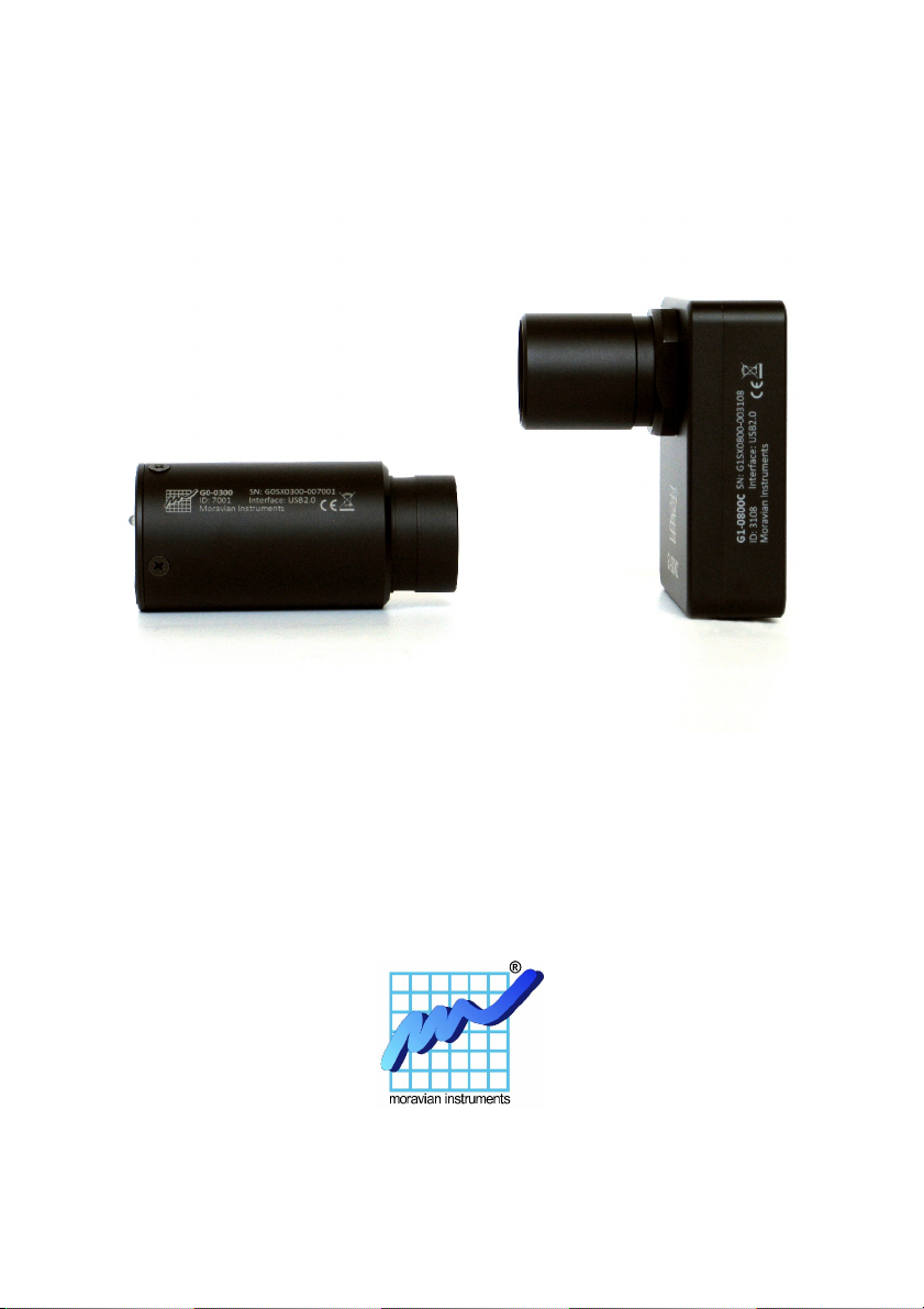
Thank you for choosing the Moravian Instruments CCD camera. These
cameras were developed to be small, lightweight and easily operated.
Despite their compactness and simplicity, they are very sensitive for use in
low-light imaging applications in astronomy, microscopy and similar areas.
G0 and G1 cameras digitize image with 16 bit precision to fully exploit
CCD chip dynamic range. Still the pixel digitization rate reaches 8 Mpx/s in
fast read mode – downloading of image containing hundreds thousands
pixels takes only a small fraction of a second. Slow read mode on the other
hand ensures very low read noise, approaching the read noise limit of the
CCD chip itself, and still provides more than 2.5 Mpx/s digitization speed.
Also important design goal of G0 and G1 cameras was USB-powered
operation. Camera is attached to the host computer only via single USB
cable, which provides both camera-to-host communication and camera
power. No separate power supply is used with G1 cameras.
Both G0 and G1 series of CCD cameras provide also the RJ-12 connector
beside the USB-B connector, which allows direct connection of the camera
head and the telescope mount equipped with the standard “autoguider” port.
This connector (together with other camera features like very fast
download, compact and lightweight construction, USB powered operation
etc.) makes using of these cameras for guiding of telescope mount very
simple. Using of G0 or G1 CCD for guiding is described later in this
manual.
Simplicity, compactness and quick image download took precedence to
some other features, so G0 and G1 series of CCD cameras lack mechanical
shutter and filter wheel. Also power provided by USB cable is not sufficient
for power-hungry thermoelectric (Peltier) coolers. This is why the CCD
chip in these cameras cannot be cooled below ambient temperature.
However, G1 cameras employ a small fan, which forces air flow inside the
camera head and removes the heat generated by camera electronics. The
CCD temperature can be lowered by many degrees Celsius compared to
sealed designs, which results to lowering of CCD thermal noise by a factor
of two or more.
4

Please note the G0 and G1 CCD cameras are designed to work in
cooperation with a host Personal Computer (PC). Computer is necessary for
operation control, image download, processing and storage as well as for
guiding. To operate G0 or G1 CCD camera, you need a computer which:
1. Is compatible with a PC standard.
2. Runs a modern 32 or 64-bit Windows operating system.
Drivers for 32-bit and 64-bit Linux systems are also provided, but
camera control and image processing software, supplied with the
camera, requires Windows operating system.
3. Provides at last one free USB port.
The G0 and G1 CCD cameras are designed to operate with
USB 2.0 high-speed (480 Mbps) hosts. Although they are fully
backward compatible with USB 1.1 full-speed (12 Mbps) hosts,
image download time can be significantly longer if USB 1.1
connection is used.
A simple and cheap device called USB hub can expand number of
available USB port. Typical USB hub occupies one computer USB
port and offers four free ports. Make sure the USB hub is USB 2.0
high-speed compatible.
But keep on mind that if more USB devices connected to one hub
need to communicate with a host PC, USB hub shares its single
up-link line to the host PC. Although G0 and G1 CCD cameras can
operate through a USB hub, it can negatively affect the camera
performance, like download time etc. It is recommended to
connect other USB devices through USB hub (e.g. the mouse) and
to provide the camera a direct USB connection to the host PC.
Also note the G0 and G1 cameras are powered from the host PC
through the USB cable. Unpowered USB hub may not provide
enough current to operate the camera. Always use USB hub with
its own power supply to connect the camera. G0 and G1 camera
power considerations are described later.
4. Alternatively it is possible to use the Gx Camera Ethernet Adapter.
This device can connect up to four Gx cameras of any type (not
only G0 and G1, but also G2, G3 and G4) and offers 1 Gbps and
10/100 Mbps Ethernet interface for direct connection to the host
5

PC. Because the PC then uses TCP/IP protocol to communicate
with the cameras, it is possible to insert e.g. WiFi bridge or other
networking device to the communication path.
The G0 or G1 CCD camera must be connected to some optical system (e.g.
the telescope) to capture images.
G1 cameras are equipped with CS-thread adapter, which allows usage of
CCTV lens with C/CS thread with the camera (it is necessary to use 5 mm
distance ring for C-mount lenses). Adapter for 1.25” telescope focuser is
screwed into the CS-thread adapter adapter.
G0 cameras are designed to be attached to the 1.25” telescope focuser only
and CCTV lenses cannot be directly used.
6

Camera Technical Specifications
The G0 series of CCD cameras comprises of the following models:
Model G0-0300 G0-0300C G0-0800 G0-0800C
CCD chip ICX424AL ICX424AQ ICX204AL ICX204AK
Resolution
656×494 656×494 1032×778 1032×778
Pixel size
7.4×7.4 µm 7.4×7.4 µm 4.65×4.65 µm 4.65×4.65 µm
Read mode Progressive Progressive Progressive Progressive
Dimension
4.9×3.7 mm 4.9×3.7 mm 4.8×3.6 mm 4.8×3.6 mm
Color mask Not present RGB (Bayer) Not present RGB (Bayer)
Interface USB 2.0 USB 2.0 USB 2.0 USB 2.0
Model G0-2000 G0-2000C
CCD chip ICX274AL ICX274AQ
Resolution
1628×1236 1628×1236
Pixel size
4.4×4.4 µm 4.4×4.4 µm
Read mode Progressive Progressive
Dimension
7.2×5.4 mm 7.2×5.4 mm
Color mask Not present RGB (Bayer)
Interface USB 2.0 USB 2.0
7

The G1 series of CCD cameras comprises of the following models:
Model G1-0300 G1-0300C G1-0301 G1-0301C
CCD chip ICX424AL ICX424AQ ICX414AL ICX414AQ
Resolution
656×494 656×494 656×494 656×494
Pixel size
7.4×7.4 µm 7.4×7.4 µm 9.9×9.9 µm 9.9×9.9 µm
Read mode Progressive Progressive Progressive Progressive
Dimension
4.9×3.7 mm 4.9×3.7 mm 6.5×4.9 mm 6.5×4.9 mm
Color mask Not present RGB (Bayer) Not present RGB (Bayer)
Interface USB 2.0 USB 2.0 USB 2.0 USB 2.0
Model G1-0800 G1-0800C G1-1200 G1-1200C
CCD chip ICX204AL ICX204AK ICX445ALA ICX445AQA
Resolution
1032×778 1032×778 1296×966 1296×966
Pixel size
4.65×4.65 µm 4.65×4.65 µm 3.75×3.75 µm 3.75×3.75 µm
Read mode Progressive Progressive Progressive Progressive
Dimension
4.8×3.6 mm 4.8×3.6 mm 4.9×3.6 mm 4.9×3.6 mm
Color mask Not present RGB (Bayer) Not present RGB (Bayer)
Interface USB 2.0 USB 2.0 USB 2.0 USB 2.0
Model G1-1400 G1-1400C G1-2000 G1-2000C
CCD chip ICX285AL ICX285AQ ICX274AL ICX274AQ
Resolution
1392×1040 1392×1040 1628×1236 1628×1236
Pixel size
6.45×6.45 µm 6.45×6.45 µm 4.4×4.4 µm 4.4×4.4 µm
Read mode Progressive Progressive Progressive Progressive
Dimension
9.0×6.7 mm 9.0×6.7 mm 7.2×5.4 mm 7.2×5.4 mm
Color mask Not present RGB (Bayer) Not present RGB (Bayer)
Interface USB 2.0 USB 2.0 USB 2.0 USB 2.0
8

CCD Chip
Sensitivity is an important feature of any CCD camera, no matter if it is
used as an imaging camera or automatic guider. Imaging camera must not
waste light gathered by the optical system to provide images with as good
signal/noise ratio as possible. Achieving of sufficient S/N ratio in rather
short time is also important to allow perfect guiding – the necessity to
accumulate light for many minutes is often unacceptable for high quality
guider. This is why the G1 cameras utilize sensitive Sony CCDs.
● The CCD quantum efficiency exceeds 50%.
● The CCD read noise is very low and reaches 5 to 10 electrons
RMS.
● G1 cameras support 16-bit digitization, significantly enhancing the
dynamic range compared to 8-bit cameras.
● Strong anti-blooming protection keeps even bright stars round,
without blooming streaks.
● G1 cameras also provide very fas readout – pixel digitization speed
is 8 Mpx/s in fast read mode.
Model G0-0300 and G1-0300
G0/G1-0300 model uses progressive-scan VGA (640×480 pixels) Sony
ICX424AL CCD chip.
Resolution
656 × 494 pixels
Pixel size
7.4 × 7.4 µm
Imaging area
4.9 × 3.7 mm
Color mask Not present
Model G0-0300C and G1-0300C
G0/G1-0300C model uses progressive-scan VGA (640×480 pixels) Sony
ICX424AQ CCD chip with Red, Green and Blue color mask (Bayer mask)
applied directly on the CCD, which allows capturing of color images by
single exposure.
Resolution
656 × 494 pixels
9

Pixel size
7.4 × 7.4 µm
Imaging area
4.9 × 3.7 mm
Color mask RGBG (Bayer mask)
Model G1-0301
G0/G1-0300 model uses progressive-scan VGA (640×480 pixels) Sony
ICX424AL CCD chip.
Resolution
656 × 494 pixels
Pixel size
9.9×9.9 µm
Imaging area
6.5×4.9 mm
Color mask Not present
Model G1-0301C
G0/G1-0300C model uses progressive-scan VGA (640×480 pixels) Sony
ICX424AQ CCD chip with Red, Green and Blue color mask (Bayer mask)
applied directly on the CCD, which allows capturing of color images by
single exposure.
Resolution
656 × 494 pixels
Pixel size
9.9×9.9 µm
Imaging area
6.5×4.9 mm
Color mask RGBG (Bayer mask)
Model G0-0800 and G1-0800
G0/G1-0800 model uses progressive-scan XGA (1024×768 pixels) Sony
ICX204AL CCD chip.
Resolution
1032 × 778 pixels
Pixel size
4.65 × 4.65 µm
Imaging area
4.8 × 3.6 mm
Color mask Not present
10

Model G0-0800C and G1-0800C
G0/G1-0800C uses progressive-scan XGA (1024×768 pixels) Sony Super
HAD ICX204AK chip with Red, Green and Blue color mask (Bayer mask)
applied directly on the CCD, which allows capturing of color images by
single exposure.
Resolution
1032 × 778 pixels
Pixel size
4.65 × 4.65 µm
Imaging area
4.8 × 3.6 mm
Color mask RGBG (Bayer mask)
Model G0-2000 and G1-2000
G0/G1-2000 model uses progressive-scan UXGA (1600×1200 pixels) Sony
ICX274AL CCD chip.
Resolution
1628 × 1236 pixels
Pixel size
4.4 × 4.4 µm
Imaging area
7.2 × 5.4 mm
Color mask Not present
Model G0-2000C and G1-2000C
G0/G1-2000C uses progressive-scan UXGA (1600×1200 pixels) Sony
Super HAD ICX274AQ chip with Red, Green and Blue color mask (Bayer
mask) applied directly on the CCD, which allows capturing of color images
by single exposure.
Resolution
1628 × 1236 pixels
Pixel size
4.4 × 4.4 µm
Imaging area
7.2 × 5.4 mm
Color mask RGBG (Bayer mask)
Model G1-1200
G1-1200 model uses progressive-scan HD (1280×960 pixels) Sony
ICX445ALA chip. The ICX445 detector is manufactured using so-called
ExView HAD technology, which enhances its sensitivity especially in red
and near infra-red portion of the spectrum. Also absolute quantum
11

efficiency of this CCD chip very high, comparable to ICX285 based
models.
Resolution
1296 × 966 pixels
Pixel size
3.75 × 3.75 µm
Imaging area
4.9 × 3.6 mm
Color mask Not present
Model G1-1200C
G1-1200C model uses progressive-scan HD (1280×960 pixels) Sony
ICX445AQA chip with Red, Green and Blue color mask (Bayer mask)
applied directly on the CCD, which allows capturing of color images by
single exposure. The ICX445 detector is manufactured using so-called
ExView HAD technology with absolute absolute quantum efficiency
comparable to ICX285 based models.
Resolution
1296 × 966 pixels
Pixel size
3.75 × 3.75 µm
Imaging area
4.9 × 3.6 mm
Color mask RGBG (Bayer mask)
Model G1-1400
G1-1400 model uses progressive-scan SXGA (1280×1024 pixels) Sony
ICX285AL chip. The ICX285 detector is manufactured using so-called
ExView HAD technology, which enhances its sensitivity especially in red
and near infra-red portion of the spectrum. Also absolute quantum
efficiency of this CCD chip is highest from all detectors used in other G1
camera models.
Resolution
1392 × 1040 pixels
Pixel size
6.45 × 6.45 µm
Imaging area
9.0 × 6.7 mm
Color mask Not present
Model G1-1400C
G1-1400C model uses progressive-scan SXGA (1280×1024 pixels) Sony
ICX285AQ chip with Red, Green and Blue color mask (Bayer mask)
12

applied directly on the CCD, which allows capturing of color images by
single exposure. The ICX285 detector is manufactured using so-called
ExView HAD technology, which enhances its sensitivity especially in read
and near infra-red portion of the spectrum.
Resolution
1392 × 1040 pixels
Pixel size
6.45 × 6.45 µm
Imaging area
9.0 × 6.7 mm
Color mask RGBG (Bayer mask)
Camera Electronics
16-bit A/D converter with correlated double sampling ensures high dynamic
range, in fact exceeding the pixel well capacity of the used CCD. Fast USB
interface ensures image download time within a small fraction of second.
Maximum length of single USB cable is 5 m. This length can be extended
to 10 m by using single USB hub or active USB extender cable. Up to 5
hubs or active extenders can be used in one connection.
Gx Camera Ethernet Adapter device allows connection of up to four Gx
cameras of any type through Ethernet interface and TCP/IP network.
Because TCP/IP protocol can be routed, the distance between camera and
host PC can be virtually unlimited.
ADC resolution 16 bits
Sampling method Correlated double sampling
Read modes Fast (8 Mpx/s)
Slow (2.5 Mpx/s)
Computer interface USB 2.0 high-speed
USB 1.1 full-speed compatible
1. Camera driver allows arbitrary software binning up to 4×4 pixels
of downloaded images.
Image download time and system read noise depends on the CCD chip used
in particular camera model and on the read mode.
13

Camera model G0/G1-0300 G0/G1-0800 G0/G1-2000 G1-1400
Download time (fast mode) 0.05 s 0.1 s 0.25 s 0.18 s
Download time (slow
mode)
0.15 s 0.32 s 0.8 s 0.58 s
1. Download times are valid for USB 2.0 host and may vary
depending on host PC. Times stated here were measured on
1.5 GHz Pentium M based laptop computer.
2. Download times can be significantly longer when connected to
USB 1.1 host.
Some electronics characteristics like system gain or system read noise
cannot be determined without knowledge of some CCD parameters (e.g.
output node sensitivity), which are not published by Sony.
CCD Chip Cooling
The G0 and G1 series of CCD cameras does not use active cooling with
Peltier TEC modules, so the CCD cannot be cooled below ambient
temperature.
Working electronics (including the CCD chip itself) produce quite amount
of heat, which rise the camera internal temperature many degrees above
ambient temperature. Because the CCD thermal noise typically doubles
every 5 or 7 °C, the thermal noise can be significantly higher after some
time of camera operation.
The G1 series of CCD cameras contain small fan, which efficiently removes
the heat from the camera body and keeps the CCD temperature as close to
ambient temperature as possible. The fan operation can be controlled from
the software.
G0 and G1 cameras also include the embedded temperature sensor, which
measures the current CCD temperature. This feature enables controlling of
the CCD temperature and ensuring the used dark frame was taken in the
same or similar temperature as the light exposure etc.
14

Power Supply
G0 and G1 cameras are powered from the USB cable. No external power
supply is necessary.
The current limit for single USB device is 500 mA from 5 V supply. The
current required by G1 CCD cameras varies depending on the camera
operation mode. The following table summarizes camera consumption.
Either way, G1 cameras do not reach the allowed 500 mA limit, defined in
USB specification.
Camera operation mode Required current
Idle, fan off 185 mA
Idle, fan on 260 mA
Image digitization, fan off 285 mA
Image digitization, fan on 360 mA
G0 cameras are not equipped with fan, so their power consumption equals
to power consumption of G1 cameras with fan off.
1. If the camera is connected through non-powered USB hub, the
current available for the connected devices can be as low as
100 mA, which is insufficient. Always use powered USB hubs
when using G1 cameras.
2. Note the so-called “active USB extender cable” is in fact nothing
more than standard USB cable with a hub with single USB
connector on the far side. Such hub consumes some energy and
may not work with G1 cameras.
3. Some USB cables incorporate very thin power lines with relatively
high resistance. If the USB device consumes several hundreds
milliamperes, the voltage drop on such cable can be around one
volt. Although the G1 camera should work, some features (e.g.
temperature measurement) may be negatively affected. Always
make sure the used USB cable is as short as possible and with lowresistance power lines.
15
G0 Camera Mechanical Specifications
G0 camera head has just 40 mm diameter (approx. 1.6 inch) and 85 mm
length (approx. 3.3 inch), including the 18 mm long 1.25” nose in the front
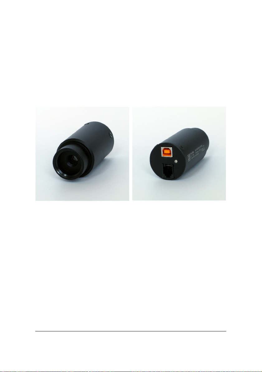
part of the camera. All connectors (USB and autoguider) are placed on the
rear side of the camera.
G0 cameras are designed to be attached directly to standard 1.25” telescope
focusers. There is no C/CS thread available, so the G0 camera cannot be
used with common CCTV lenses.
16
Illustration 1: G0 camera head

Illustration 2: G0 camera dimensions
The G0 cameras use Interline Transfer CCDs allowing electronic exposure
control, so they do not contain mechanical shutter. But it is necessary to
cover the telescope manually to take dark or bias frame.
Internal mechanical shutter No
Shortest exposure time 0.000125 s
Longest exposure time Limited by chip saturation only
Head dimensions 40 mm (diameter) × 85 mm (length)
Camera head weight 0.1 kg
G1 Camera Mechanical Specifications
Compact and robust camera head measures only 83 × 76 × 26 mm (approx.
3.25 × 3 × 1 inch). The head is CNC-machined from high-quality aluminum
and black anodized.
The camera is supplied with CS adapter for connecting various CS
compatible lenses. The C-thread to 1.25" adapter can be screwed into the
head to attach the camera to any telescope focuser accepting standard 1.25"
eyepieces.
17

Both C and CS standards use the same thread specification (C-thread with
1 inch diameter, 32 threads per inch). The difference between them is in the
back focal distance – while the standard C-thread back focal distance is
17.5 mm, the CS back focal distance is 12.5 mm. Both variants are available
for G1 CCD cameras.
The G1 cameras use Interline Transfer CCDs allowing electronic exposure
control, so they do not contain mechanical shutter. But it is necessary to
cover the telescope manually to take dark or bias frame.
Internal mechanical shutter No
Shortest exposure time 0.000125 s
Longest exposure time Limited by chip saturation only
Head dimensions 83 mm × 76 mm × 26 mm
Back focal distance 12.5 mm (CS standard)
17.5 mm (C standard)
Camera head weight 0.2 kg
1. Camera dimensions do not include the CS-thread adapter. This
adapter depth is 6.4 mm, so the camera depth including the CSthread adapter is 32.4 mm.
18
Illustration 3: G1 camera head
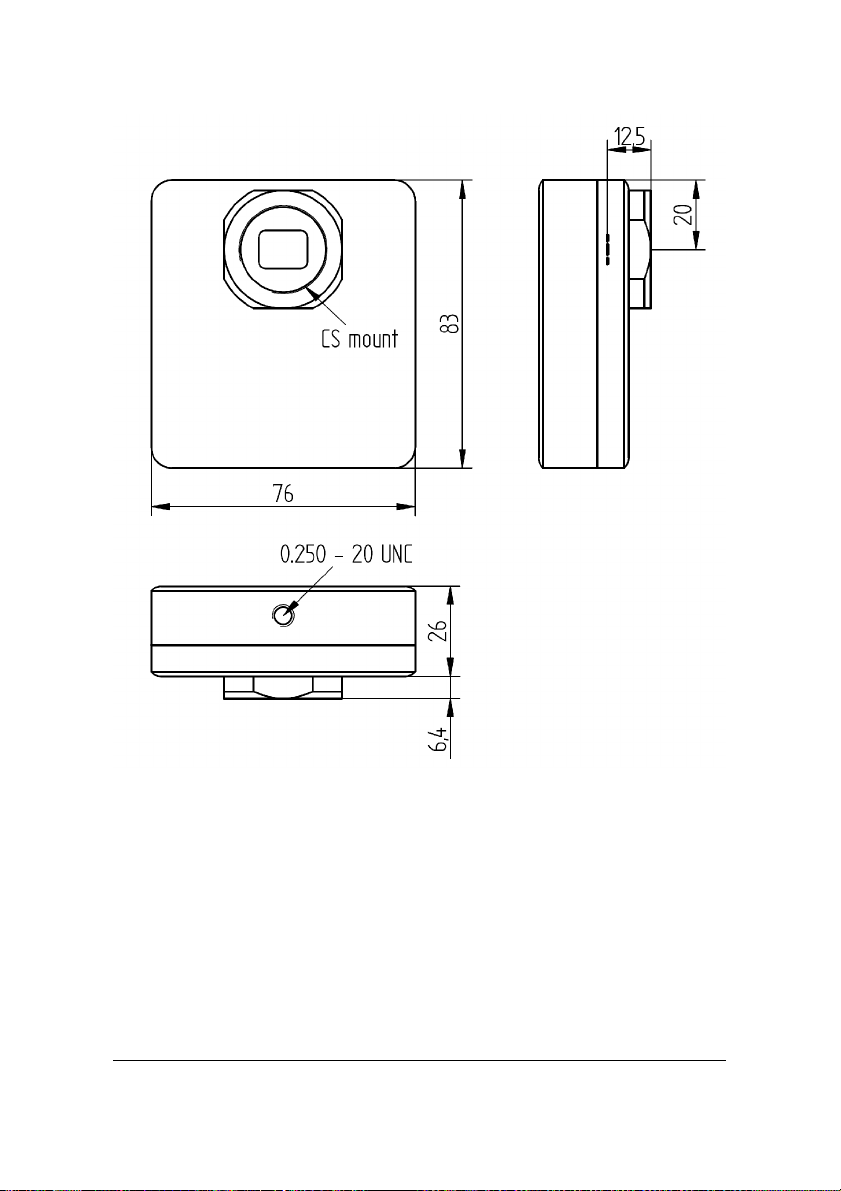
Illustration 4: G1 camera dimensions
19

Guiding
A lot of astronomical telescope mounts (especially the mass-manufactured
ones) are not precise enough to keep the star images perfectly round during
long exposures without small corrections. Astronomical CCD cameras and
digital SLR cameras allow perfectly sharp and high-resolution images, so
even a small irregularity in mount tracking appears as star image
deformations. G0 and G1 CCD cameras were designed especially with
automatic mount guiding on mind.
The G0 and G1 cameras were designed to operate without any mechanically
moving parts (with the exception of magnetically levitating fan used in G1
cameras). Electronic shutter allows extremely short exposures and also
obtaining thousands of images in a short time, which is necessary for
quality guiding. CCD chips used in G0 and G1 cameras are sensitive
enough to capture even a faint stars within few seconds. The limiting
magnitude of G0 and G1 cameras is much higher compared to the most
sensitive TV or Web cameras.
G0 and G1 cameras work in connection with a host computer (PC). Guiding
corrections are not calculated in the camera itself, it only sends acquired
images to the PC. The software running on the PC calculates the difference
from required state and sends appropriate corrections to the telescope
mount. The plus side of using a host PC CPU to process images is the fact,
that current PCs provide overwhelming computational power compared to
any embedded processor inside the guiding camera. Guiding algorithms
then can determine star position with sub-pixel precision, can match
multiple stars to calculate average difference, which limits the effects of
seeing, etc.
Calculated corrections can be sent back to mount using PC-to-mount link,
but more accurate guiding can be achieved using so called “Autoguider”
port. It is enough to connect the G0 or G1 camera and the mount using 6wire cable and guide the mount through the camera.
20
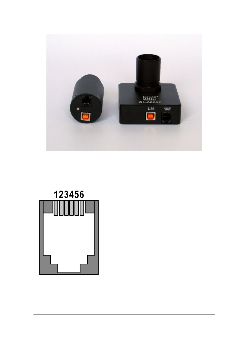
Illustration 5: Bottom side of the G0 and G1 camera heads with USB
The Autoguider port follows the de-facto standard introduced by SBIG ST4 autoguider. The pins have the following functions:
1. R.A. + (Right)
2. Dec + (Up)
3. Dec – (Down)
4. R.A.– (Left)
5. Common (Ground)
6. Not connected
21
and Autoguider connectors

The maximum sinking current of each pin of the G0 or G1 camera is
100 mA. If the mount does not treat the autoguider port as logical input
only, but switches the guiding motors directly by these signals, a relay box
must be inserted between the camera and the mount. The relay box ensures
switching of currents required by the mount.
22

Camera Maintenance
The G0 and G1 cameras require no special maintenance. However, it is
a precision optical and mechanical instrument so it should be handled with
care. Camera should be protected from moisture and dust. Always cover the
telescope adapter when the camera is removed from the telescope or put the
whole camera into protective plastic bag.
Changing the Telescope Adapter of the G1 Camera
The 1.25" telescope adapter is screwed into the camera CS adapter. If you
intend to use the camera with some CS compatible lens or microscope with
C-thread adapter, simply unscrew the 1.25" adapter.
There are two standards using the C-thread (C-thread has 1 inch diameter
and 32 threads per inch), differentiated by the back focal distance. The C
standard has 17.5 mm back focal distance while the CS standard has
12.5 mm back focal distance.
G1 CCD cameras can be supplied with either C or CS adapter. This usually
has no importance if the camera is used with the telescope, because the
telescope focuser can easily compensate the difference. But certain lenses
are designed either for C or CS standard.
While it is possible to use the distance ring to prolong the CS adapter to C
standard, it is not possible to use the CS lens with full length C adapter. The
C and CS adapters used on G1 cameras can be replaced, but camera mus be
returned to manufacturer for such exchange.
23
 Loading...